Cold Foil Inline Vision Registration Calibration across Shift Operations
Cold foil inline vision systems maintain registration across shifts by matching strobe sensor geometry to substrate thermal growth and adhesive rheology changes.


Lens
Inline machine vision systems mounted on high-speed flexo presses capture real-time imagery of cold foil transfer boundaries at web speeds up to two hundred fifty meters per minute. The camera assembly detects microscopic registration deviations between the UV-cured adhesive pattern and the metallic foil layer. Achieving continuous measurement accuracy requires precise spatial positioning of the optical assembly relative to the web path, along with high-frequency illumination strobing tied to cylinder rotation encoders.
When cold foil runs inline on multi-station flexographic or offset presses, registration errors show up as unfoiled voids along graphic edges or exposed adhesive halos. Inspection systems use high-resolution line-scan or area-scan sensors mounted just downstream of the foil nip assembly. The optical layout sets the contrast limit between the reflective foil surface and the variable reflectivity of the substrate below.
Poor mounting angles or improper depth of field introduce optical distortion, causing software to flag false positional errors.
Optical performance depends on keeping image capture strictly synchronized with web speed. A rotary encoder on the chill roll or plate cylinder shaft sends high-density pulse trains that trigger camera shutters at fixed spatial increments. At line speeds above three meters per second, flash durations must stay below five microseconds to freeze web movement without blurring target edges.
The uniformity of the light field across the web width determines how cleanly the camera marks the boundary between metallic foil and bare substrate.
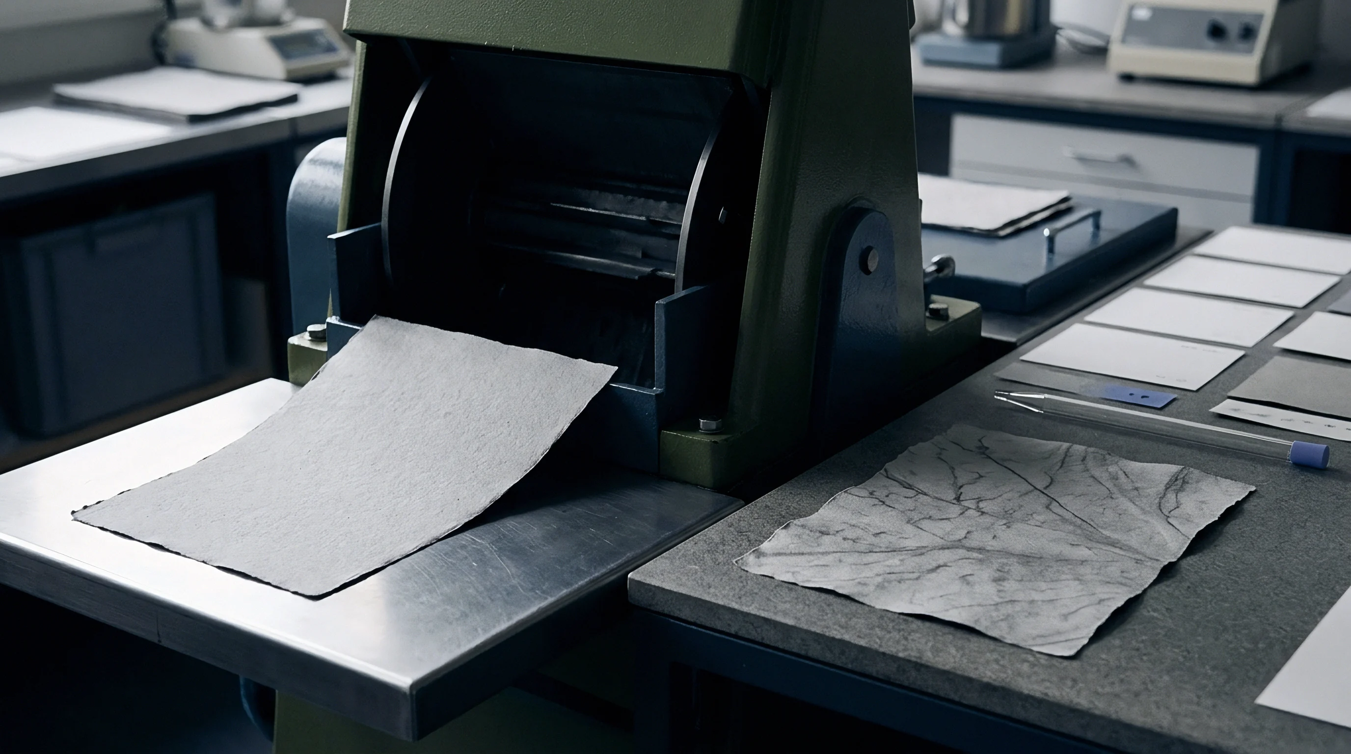
Image Acquisition Architecture on Flexographic Press Lines
Charge-coupled device arrays paired with monochromatic LED strobe bars capture register marks on the web before post-cure inspection. Line-scan cameras read the image line by line, building a continuous two-dimensional bitmap as the substrate travels underneath. This setup works reliably on narrow and wide web lines because it avoids the framing distortion that area-scan sensors suffer when press vibration occurs.
Sensor resolutions for cold foil inspection usually run from four thousand to sixteen thousand pixels per line array. That pixel density sets the smallest physical offset the vision software can resolve. An eight-thousand-pixel camera across a five-hundred-millimeter web width, for instance, provides a raw optical resolution of roughly sixty-two micrometers per pixel.
Sub-pixel interpolation algorithms then divide each pixel into sixteenths, giving a theoretical measurement precision down to four micrometers in stable, vibration-isolated setups with optimal lighting.
Lens selection directly shapes depth of field and mechanical tolerance. Fixed focal length lenses with low-distortion glass minimize warping around the edges of the field. When web flutter crops up from tension surges or long unsupported spans, shifts in the focal plane distort local image scale.
Telecentric lenses eliminate these scaling changes caused by Z-axis web movement, keeping distance measurements between registration marks true even as the substrate bounces slightly.
A line scan camera operating at a strobe rate of 12 kilohertz achieves a spatial resolution of 0.035 millimeters per pixel when the web runs at 180 meters per minute under calibrated D50 strobe lighting.
Lighting selection decides how reliably software detects edges across different substrates. Standard diffuse white light fails on mirror-finish aluminum foil over coated board because specular reflection over-saturates the pixels and blinds the vision processor. Polarized setups cut through that glare, revealing structural contrast between foil edges and the underlying fiber network.
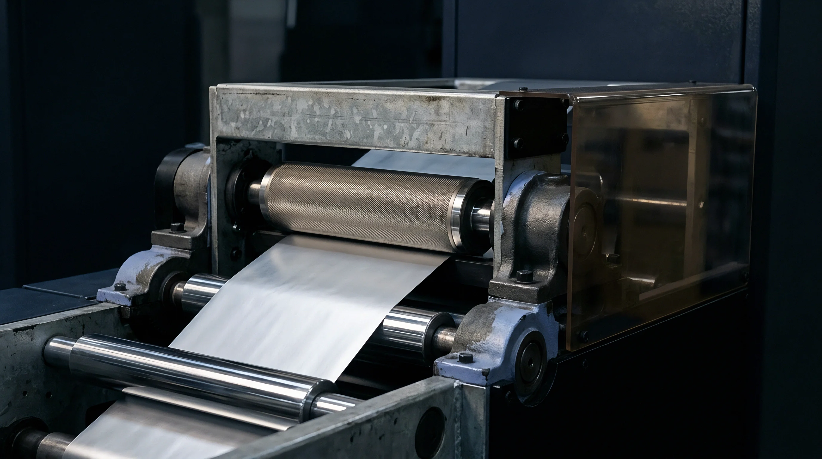
Specular Reflectance and Illumination Geometry
Foiled areas reflect light directionally, blinding standard sensors mounted normal to the web plane. Getting clear contrast requires off-axis angled lighting or dual brightfield-darkfield channels. Brightfield setups position the light source and camera sensor at matching complementary angles so specular reflections head straight into the lens.
In brightfield images, metallic foil shows up bright white while bare substrate scatters light away and looks dark.
Darkfield lighting flips that contrast by aiming light at shallow, grazing angles across the web surface. Flat foil reflects light away from the lens, appearing dark or black. Substrate fibers, adhesive squeeze-out ridges, and loose foil flakes scatter the grazing light up into the lens, showing as bright highlights against a dark foil backdrop.
This geometry works especially well for catching fine foil tearing, adhesive bleed, and trailing flakes around detailed lines.
| Substrate Category | Illumination Mode | Optical Angle (Degrees) | Contrast Ratio (Foil to Stock) | Minimum Edge Threshold (mm) |
|---|---|---|---|---|
| Coated Folding Cartonboard | Brightfield Coaxial | 0 (Perpendicular) | 12:1 | 0.025 |
| Uncoated Kraft Paperboard | Darkfield Grazing | 75 Off-Axis | 18:1 | 0.040 |
| Clear Polypropylene Film | Transmissive Backlight | 180 Direct Line | 25:1 | 0.015 |
| Metallized PET Laminate | Cross-Polarized Diffuse | 45 Dual Channel | 8:1 | 0.050 |
Matching the lighting wavelength to the adhesive chemistry and foil tint sharpens edge definition. Monochromatic red or green LED arrays minimize chromatic aberration in optical lenses, yielding cleaner pixel transitions along graphic boundaries. Blue LED light at a four-hundred-sixty-nanometer wavelength improves contrast when inspecting foil laid over dark flexo inks or clear films, giving target-tracking software sharper transitions to lock onto.

Optical Hardware Failure Modes
Dust buildup on cover glass causes false contrast readings that skew auto-tracking within fifty thousand impressions. Paper dust, atomized adhesive, and loose foil flecks continuously drift toward optical enclosures on high-speed runs. Static charges on synthetic webs pull fine particles straight onto lens surfaces, scattering light and degrading image contrast over a shift.
Airborne dust inevitably coats camera lenses, making scheduled cleaning mandatory alongside mechanical surface wipers.
Press frame vibration degrades optical alignment during long high-speed runs. Web tension spikes, plate cylinder gap bounce, and gear mesh create high-frequency oscillations along mounting rails. Left unmanaged, this vibration blurs line-scan images, spreading sharp target edges over multiple pixel rows and ruining measurement repeatability.
- Optical Surface Fouling occurs when airborne paper dust and atomized UV adhesive settle on lens elements, scattering strobe light and dropping signal contrast below detection thresholds.
- Vibrational Blur Displacement results from press frame resonance shaking camera support rails, spreading single-pixel edge boundaries across multiple sensor rows and skewing registration feedback loops.
- Strobe Illumination Decay develops as LED arrays age or degrade thermally, dropping light output and forcing auto-exposure software to compensate by raising gain.
- Encoder Signal Jitter stems from mechanical wear in coupling gears or electrical noise on signal lines, triggering the camera unevenly and creating false spatial stretching along the web axis.
- Lens Thermal Expansion occurs when ambient temperature rises inside unventilated camera housings, altering element spacing and shifting the focal point over long runs.
To control vibration, vision camera frames anchor directly to floor-mounted isolation dampers rather than floating press bridges. Carbon fiber mounting rails supply rigidity while dampening high-frequency press shake. Pressurizing sealed optical enclosures with clean, oil-free compressed air maintains positive internal pressure, keeping dust and vapors out throughout a shift.

Camera Enclosure Thermal Stabilization
Image sensors experience pixel sensitivity drift once ambient temperatures around the mounting bracket climb past thirty-five degrees Celsius. Press rooms swing through wide temperature shifts between morning startup and peak afternoon runs. Heat from nearby UV curing lamps, web dryers, and drive motors soaks into camera enclosures, shifting the sensor baseline.
Thermal sensor drift introduces image noise, dark current accumulation, and fluctuating pixel gain sensitivity. When processing uncompensated images, signal processing algorithms mistake thermal noise for physical spatial displacement and issue unnecessary registration corrections. Cooling jackets using closed-loop chilled water or vortex air tubes keep camera housing temperatures within plus or minus one degree Celsius.
Water-cooled camera enclosures stabilize optical baseline calibration on narrow web lines. Keeping internal optical temperatures steady eliminates phantom registration corrections during three-hour heat buildup cycles on continuous foil runs. Lens assemblies built with temperature-compensated housing metals hold optical elements at precise focal distances across twenty-four-hour shift schedules.
Software baseline averaging routines filter out mild environmental temperature drift, though camera pixel drift from press frame vibration still causes measurement errors when line speed exceeds one hundred eighty meters per minute.


Drift
Heat buildup inside printing cylinders, combined with gradual web expansion over an eight-hour shift, causes steady dimensional distortion in cold foil alignment. Normal press operation generates continuous heat that transfers into side frames, plate cylinders, and web guides. As these mechanical components expand, baseline distances between the adhesive station and the UV foil laminating nip gradually shift.
Cold foil processing demands tight alignment between two distinct inline steps: printing UV-curable adhesive with a flexo plate and pressing the metallic foil against the wet adhesive inside a high-pressure nip. Machine components shift their spatial alignment as the shift wears on. A web running in perfect register during morning startup drifts off target as the press frame absorbs heat from UV lamps and gear friction.
Substrates react differently under heat and tension. Paperboard loses moisture as it passes hot UV curing stations, shrinking laterally while web tension stretches it longitudinally in the machine direction. Filmic stocks like polypropylene or polyethylene have high thermal expansion coefficients and stretch considerably under tension at elevated press temperatures.
Register drift is simply the cumulative effect of these physical changes over time.

What Causes Vision Systems to Drift off Register?
Frictional heat from main drive gearboxes migrates into the side frames, causing localized thermal expansion across plate cylinders. Aluminum or steel flexographic plate cylinders experience measurable circumferential growth as core temperatures rise during long production runs. A fifteen-degree Celsius temperature rise expands a standard six-hundred-millimeter circumference cylinder by more than 0.11 millimeters, shifting the printed adhesive pattern relative to downstream foil impression rolls.
Thermal expansion moves the cylinders away from nominal settings, and cold foil demands exact alignment. As web stretch induces lateral drift, servo motors continually adjust registration while heat alters adhesive viscosity in the fountain.
Tension fluctuations compound thermal cylinder expansion. Control systems rely on load cell feedback to maintain steady web tension across unwind, print, and rewind zones. But as web temperature rises, the substrate modulus of elasticity drops.
Held under constant mechanical tension, a warm web stretches farther than a cold one, creating longitudinal drift that vision systems must continuously track and correct.
Temperature variations in the adhesive change fluid rheology inside flexo ink fountains. Cold adhesive has high viscosity, resulting in heavier film transfer and slight dot gain. As friction warms the adhesive pan, viscosity drops and thins the laydown, shifting the effective printed edge boundary measured by inline cameras.
This dimensional shift in the adhesive outline mimics real registration movement, even when physical plate alignment hasn’t moved at all.
Thermal Expansion Metrics across Cylinder and Web Assemblies
Aluminum plate cylinders expand in diameter by roughly twelve micrometers for every five-degree rise in core temperature. Wide-web lines running at three hundred meters per minute build up substantial thermal energy within three hours of continuous operation. Thermal imaging maps confirm drive-side frames reach operating temperatures eight to twelve degrees higher than operator-side frames, driven by gear friction and motor proximity.
Asymmetrical frame expansion throws cylinders out of parallel alignment, creating web tracking slant across the printing nip. When a cylinder expands slightly more on the drive side, it establishes a tension gradient across the web width. That lateral skew forces the web to wander toward the lower-tension side, causing diagonal register drift that standard circumferential compensators cannot fix on their own.
| Running Hour | Frame Temperature (C) | Cylinder Temp Delta (C) | Lateral Offset (mm) | Longitudinal Offset (mm) |
|---|---|---|---|---|
| Hour 0 (Cold Start) | 21.5 | 0.0 | 0.000 | 0.000 |
| Hour 2 | 27.8 | +4.2 | +0.035 | +0.048 |
| Hour 4 | 33.1 | +8.6 | +0.072 | +0.095 |
| Hour 6 (Steady State) | 36.4 | +11.1 | +0.098 | +0.132 |
| Hour 8 | 37.0 | +11.8 | +0.104 | +0.141 |
| Hour 12 (Extended Shift) | 37.5 | +12.2 | +0.110 | +0.148 |
Moisture loss during UV curing adds further structural distortion. Coated folding boxboard passing beneath high-intensity UV lamps sees localized surface heating up to eighty degrees Celsius. Rapid moisture loss shrinks board width by up to 0.08 percent across a one-meter web, pulling margin registration marks inward toward the centerline.
Inspection software has to account for this cross-web shrinkage so it doesn’t trigger false web-steering signals.
Cold foil adhesive viscosity stabilized at running temperature prevents web distortion better than constant tension adjustments applied at the unwind reel.
Tension stability controls structural elongation in the machine direction. Filmic webs under excessive tension suffer neck-in, where longitudinal stretching forces cross-web narrowing. When the press accelerates from make-ready speed to full output, web tension spikes briefly before closed-loop dancers pull the tension zone back into balance.
That acceleration surge causes transient register drift that demands active, predictive speed-compensation curves inside press drive software.
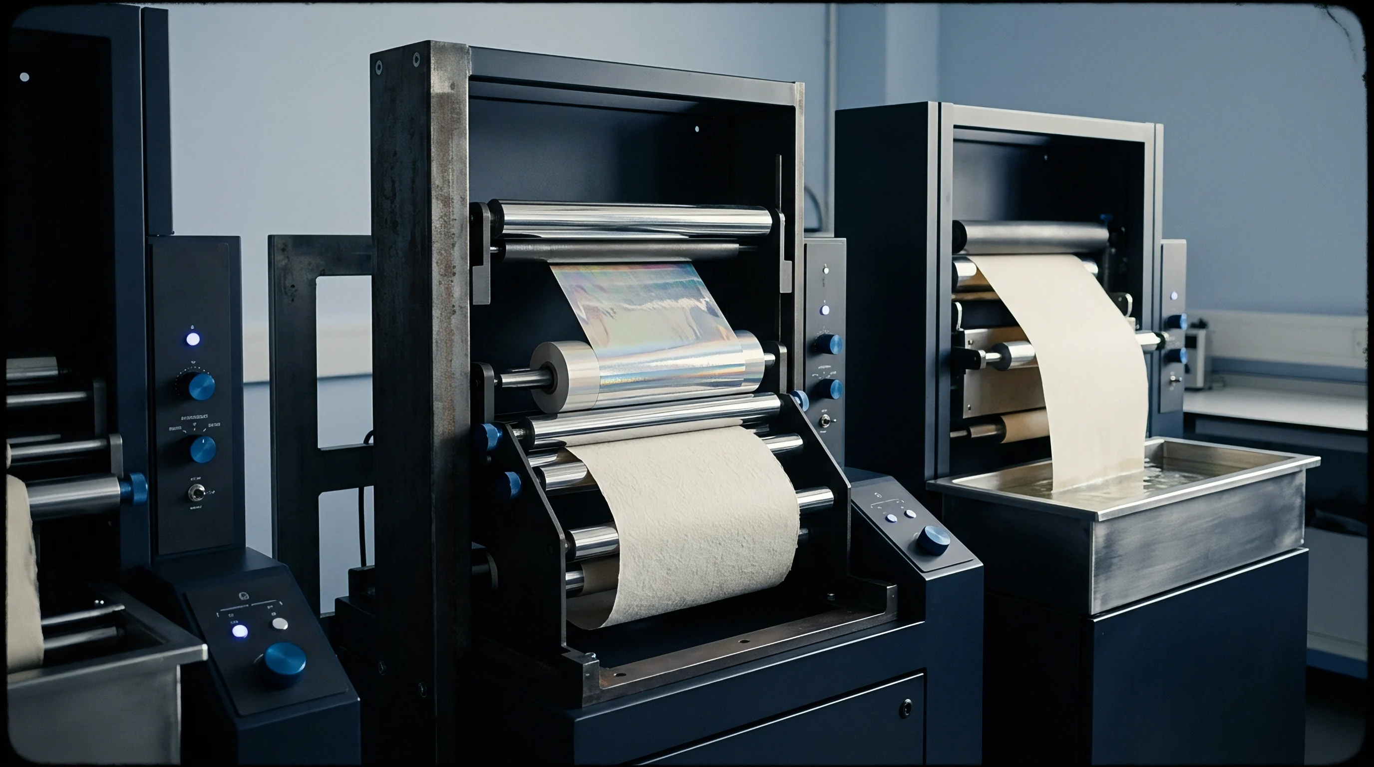
Viscosity and Adhesive Film Thickness Dynamics
UV-curable adhesives thin out as friction warms the fountain pan, dropping transfer viscosity from nine hundred down to six hundred centipoise. Lower viscosity changes fluid dynamics across the metering roll, doctor blade, and photopolymer plate. With less fluid resistance, the adhesive squeezes wider under nip pressure, expanding fine line details by ten to twenty micrometers.
Vision systems tracking image contours can interpret graphic line growth as a directional spatial error. If an adhesive line expands outward by fifteen micrometers, an uncalibrated algorithm registers an offset on both leading and trailing edges. Higher-end software uses grayscale edge gradient analysis to separate real physical displacement from simple dot gain or adhesive spread.
Logging spatial displacement across a twelve-hour production run on seventy-micrometer oriented polypropylene film showed heat buildup in the curing zone pulling web registration off center by 0.18 millimeters within the first four thousand meters. Installing temperature-controlled metering rollers stabilized fluid transfer, cutting edge expansion drift to under five micrometers across subsequent shifts.
Static charges along filmic webs attract particulate contamination that interferes with adhesive wet-out. Charges above fifteen kilovolts disrupt uniform adhesive transfer, causing ragged edges along cold foil boundaries. Those ragged edges scatter illumination unevenly, introducing digital noise that degrades vision tracking precision.

Shift Transition Baseline Zeroing Sequence
Press operators coming on shift run a baseline calibration pass before locking automated tracking. Shift handovers carry high risk for registration drift because incoming crews frequently tweak mechanical press controls without verifying optical vision baselines. Following a standardized zeroing routine prevents operator-induced calibration errors.
Because cold foil requires exact alignment and clean mark edges, operators check camera offsets early, ensuring static interference or temperature-driven plate expansion won’t compromise tracking.
- Inspect camera protection glass for paper dust or oil mist and clean using microfiber optical wipes soaked in isopropyl alcohol.
- Verify ambient light shield positioning so press room overhead lighting cannot penetrate the camera field of view.
- Run the web at slow thread speed to check web guide centerline alignment against press frame baselines using manual bench measurements.
- Print a test target matrix containing zero-point calibration marks at standard operational adhesive volume.
- Stop the web and acquire a stationary optical reference image using the vision system’s manual zero command.
- Cross-check camera measurement accuracy with a forty-power optical shop microscope against a physical master grid plate.
- Engage dynamic vision feedback tracking and accelerate the press smoothly to target running velocity.
Following this sequence ensures inspection software calculates positional error relative to actual mechanical zero rather than an unverified baseline. Skipping manual microscope validation can lock uncompensated mechanical drift into software reference files, perpetuating registration errors throughout the entire shift.
Operators lock in web tension baselines before adjusting camera tracking parameters when correcting cold foil register errors.


Target
Registration marks in the trim margin give inline vision software the spatial reference points needed to measure positional offset. Target geometry dictates how fast, accurate, and stable tracking algorithms perform. Standard crosshairs designed for manual eye-loupe inspection fail under high-speed automated processing because they lack sufficient contrast and pixel density along diagonal vectors.
Automated vision registration uses target geometries specifically engineered for high-frequency digital line sampling. Effective target patterns pair solid right-angle edges with defined specular contrast zones, creating sharp intensity transitions across both horizontal and vertical pixel rows. The spatial relationship between the printed adhesive mark and the cold foil knockout frame defines the registration displacement vector in two-dimensional space.
Inline vision software continuously calculates the centroid coordinates of printed targets, comparing real-time positions to master reference coordinates set during setup. If positional deviation crosses pre-set control boundaries, the system calculates corrective servo motor steps and sends pulse commands to the register drive boards. Keeping processing latency low ensures fast mechanical response before drift exceeds commercial limits.

Registration Mark Design Geometry and Contrast Verification
Crosshairs paired with solid foil contrast blocks deliver reliable edge coordinates for real-time spatial calculation algorithms. High-speed vision systems need targets that yield high spatial frequency information along both machine direction and cross-machine axes. Solid L-shaped targets with three-millimeter legs and 0.5-millimeter line widths offer optimal pixel density for line-scan cameras.
Placing foil contrast blocks next to printed adhesive targets lets vision software sample background lighting levels continuously. Variations in substrate brightness, coating patchiness, or ink density alter baseline reflectance as rolls run. Sampling background reflectance in real time normalizes threshold parameters, keeping edge detection sensitivity stable across varying web surfaces.
Where targets sit on the web layout directly affects measurement accuracy. Placing mark pairs only along outer trim margins leaves tracking vulnerable to web edge weave and tension flutter. Trim margins bounce significantly more than center zones.
Distributing mark pairs across operator-side, center, and drive-side lanes allows software to calculate web skew and thermal trapezoidal stretch across the entire printed width.
Compliance with ISO 12647-2 registration tolerances requires that total cold foil overlap deviation remains below 0.10 millimeters across 95 percent of produced sheets.
Specialized micro-targets measuring under one square millimeter can sit inside functional bleed areas or box glue flaps. Micro-targets eliminate the trim waste required by wide clear margins while still providing accurate spatial coordinates for camera arrays. High-magnification telecentric lenses monitor micro-targets without losing edge definition or distorting graphic edges.
Closed Loop Feedback Latency and Motor Response Calculations
Response lag between error detection at the camera and physical correction at the motor rail creates scrap during speed adjustments. Total closed-loop timing combines image acquisition, frame grabber transfer, processing calculations, control network pulses, and servo motor response. System latency must stay under fifty milliseconds to avoid over-correction hunting during speed ramps.
Processing algorithms split captured bitmaps into small regions of interest around target locations. Restricting analysis to these small zones cuts computational load, raising frame processing speeds from thirty frames per second to five hundred frames per second. That speed boost allows real-time inspection of every sheet impression on presses running up to two hundred meters per minute.
| Encoder Resolution (PPR) | Web Distance per Pulse (mm) | Calculation Latency (ms) | Correction Delay at 200 m/min (m) | Residual Error Window (mm) |
|---|---|---|---|---|
| 1,000 | 0.3140 | 45 | 0.150 | 0.080 |
| 5,000 | 0.0628 | 22 | 0.073 | 0.035 |
| 10,000 | 0.0314 | 12 | 0.040 | 0.018 |
| 36,000 | 0.0087 | 4 | 0.013 | 0.005 |
As line speeds increase, closed-loop latency becomes critical. High-density pulse arrays optimize motor step precision, allowing servo motors to make fine registration adjustments based on logged spatial displacement.
Linear motor actuators on plate cylinder shafts make circumferential and lateral positional adjustments in sub-micron steps. Motor response dynamics have to match web acceleration profiles so they don’t overshoot baseline targets. PID control loops tuned specifically to press web dynamics damp mechanical oscillation, keeping step transitions smooth during dynamic recovery.

Matrix Offset Calibration Protocols
Operators establish a zero-point spatial matrix by checking physical foil impressions against digital art files with a bench microscope. Physical zero rarely aligns perfectly with artwork coordinates due to plate mounting tolerances, plate tape thickness variations, and web path length variances. Matrix calibration maps those physical press discrepancies and stores an offset matrix in vision memory.
Matrix offset zeroing aligns vision coordinates with actual master print geometry before automated tracking starts. Uncalibrated vision tracking tries to force the press into alignment with an abstract digital coordinate frame, driving mechanical cylinders against limit switches or generating constant registration oscillation. Establishing verified matrix offsets grounds software commands in machine reality.
- Physical Impression Verification requires pulling a proof sheet and measuring target distance vectors with a calibrated toolmaker microscope to establish true baseline values.
- Electronic Grid Mapping involves scanning target matrices across nine web locations to calculate non-linear spatial distortion from web stretch or cylinder bowing.
- Camera Gain Normalization requires adjusting illumination output and sensor amplifier gain until target contrast curves produce sharp vertical square-wave profiles.
- Zero Offset Memory Storing locks measured optical coordinates into press memory as absolute baseline values before engaging automated tracking.
- Dynamic Speed Slope Setting involves recording registration shift across four distinct velocity steps to build proportional speed compensation curves.
Recalibrating matrix offsets is mandatory after flexo plate changes, adhesive lot variations, or major substrate switches. Operating with legacy matrix offsets generated for a different caliper creates permanent offset errors that vision tracking software cannot resolve automatically.

Speed Ramping Compensation Curves
Accelerating from idle to full production changes web stretch dynamics, requiring dynamic register offsets pre-programmed into press drive firmware. Web tension shifts non-linearly during speed ramps because roll inertia, dancer friction, and motor response lag behind at different rates. Without predictive speed compensation, vision registration systems produce significant scrap during acceleration passes.
Predictive software maps registration offset values against line speed to build dynamic velocity correction curves. When press controls initiate acceleration, the system applies pre-emptive motor adjustments based on stored speed profiles before cameras even detect target drift. That pre-emptive shift holds registration within limits throughout the ramp cycle.
Speed ramp compensation curves evaluated on an eight-color flexo line running cold foil packaging stock showed that uncompensated acceleration passes generated twenty-eight meters of out-of-register waste per ramp. Turning on predictive velocity curves reduced acceleration scrap to under three meters per ramp cycle, saving substantial substrate and foil across shifts.
Continuous dynamic speed adjustments maintain baseline registration across changing press speeds. Matching software correction rates to mechanical cylinder response profiles prevents overshooting and oscillation during rapid velocity changes.
Whether high-resolution camera sensors can process micro-embossed reflective foil surfaces without generating phantom registration errors remains an open question among optical sensor designers.

Disparity
Commercial friction between print buyers and packaging converters often comes down to small registration offsets accumulated during long production runs. Metallic foil accents create sharp focal points on luxury packaging, so even minor misalignment between foil elements and underlying process print distorts visual graphic boundaries, triggering rejections during receiving audits.
Understanding tolerance limits means separating technical press capability from practical production reality. Modern inline flexo presses hold mechanical registration within plus or minus 0.05 millimeters in stable laboratory conditions. But running commercial packaging jobs across multiple shifts brings thermal variation, substrate caliper shifts, and operator interventions that widen true operational register bands to plus or minus 0.15 millimeters.
Setting explicit reject limits in written delivery contracts protects converters and brand owners alike from subjective quality disputes. Packaging specifications need to state maximum allowable registration offsets in clear metric units, tied to formal sampling plans derived from international standards. Vague contract language calling for perfect alignment or zero defects inevitably leads to rejected shipments and unpaid invoices.

Commercial Tolerances and Defect Thresholds
Brand owners specifying metallic accents on retail folding cartons set tight reject limits for unfoiled gaps or halos. Acceptable registration variance depends heavily on design complexity and contrast between the foil and background print. Fine typography, detailed line art, and narrow reverse-type knockouts require far tighter register control than broad geometric foil blocks.
| Packaging Category | Design Feature Complexity | Standard Tolerance (mm) | Tight Tolerance (mm) | Critical Reject Boundary (mm) |
|---|---|---|---|---|
| Pharmaceutical Folding Boxes | Micro-Type / Braille Foil | +/- 0.080 | +/- 0.050 | > 0.100 |
| Cosmetics Luxury Cartons | Fine Line / Multi-Pass Outline | +/- 0.100 | +/- 0.075 | > 0.125 |
| Beverage Pressure Labels | Solid Spot Foil Accent | +/- 0.150 | +/- 0.100 | > 0.200 |
| Fast-Moving Consumer Goods | Large Graphic Background Block | +/- 0.200 | +/- 0.150 | > 0.250 |
Foil overlap design strategies directly influence reject rates. Graphic designers who build generous trap margins under metallic foil give converters a helpful safety buffer. A trap margin of 0.20 millimeters allows applied foil to shift slightly without exposing raw paperboard or ink, preventing visible halo defects during transient registration swings.
Reject claims surge when designs use butt-fit registration, where foil edges meet dark ink without overlapping trap zones. Butt-fit layouts demand sub-fifty-micrometer registration consistency across full shifts. Converters who accept butt-fit jobs without charging higher setup fees or budgeting wider waste margins take on heavy financial risk when vision systems flag micro-mismatches at high speeds.

Waste Generation Arithmetic during Registration Recovery
Calculating scrap costs means factoring in both substrate tonnage and expensive cold foil consumption during correction cycles. When an inline camera detects an out-of-tolerance error, press software initiates automated motor corrections. The substrate that passes through the laminating station while motors move represents direct material scrap.
For example, a press running at two hundred meters per minute moves 3.33 meters of web per second. If system latency, calculation delay, and motor reaction time total three seconds, the press outputs ten meters of out-of-spec scrap per correction event. On a 1080-millimeter-wide web running high-grade folding boxboard and premium cold foil stock, waste costs add up quickly over repeated recovery cycles.
Uncalibrated vision systems generate higher scrap volumes through unnecessary offset hunting than total camera failures generate through undetected registration drift.
Modeling confirms that constant micro-hunting by overly aggressive feedback loops increases shift waste. If camera sensitivity is set too tight, normal mechanical web vibration triggers constant minor motor adjustments. The registration system stays in permanent oscillation, churning out marginal scrap rather than settling into a steady state.
Optimizing loop damping factors balances correction speed against motor hunting stability. Setting a dead-band buffer of plus or minus 0.03 millimeters prevents vision software from reacting to transient noise, saving mechanical corrections for genuine drift trends. Properly dampened control loops cut overall scrap across an eight-hour shift while keeping finished production safely within customer specs.
Shift Handover Logging Practices
Documenting sensor calibration metrics in press logs establishes traceability when quality audits occur weeks after delivery. Vision systems generate continuous digital log files recording target offsets, line speeds, web tension, and corrective motor actions throughout every run. These archival logs prove delivered pallets met agreed quality parameters during production.
Shift handovers require a formal review of vision inspection logs between outgoing and incoming press crews. Reviewing spatial drift trends over preceding hours alerts incoming operators to thermal growth, adhesive viscosity changes, or dust accumulating on camera lenses. Early trend detection enables preventative recalibration before quality drops past critical reject limits.
Digital quality logs linked to roll numbers or pallet barcodes create unalterable production histories. If print buyers report registration defects in delivered shipments, converters cross-reference defect lot numbers against high-speed vision archives. That traceability analysis reveals whether defects occurred during press acceleration passes or during downstream converting processes like die-cutting, embossing, or folding box gluing.
Section 14.2 of the European Carton Packaging Agreement specifies that registration deviations under 0.15 millimeters on metallic foil passes represent standard trade quality unless tighter tolerances were explicitly written into the purchase contract, shifting liability back to the buyer for rejected press runs.