Low-Shear and High-Shear Viscometry Calibration in Paper Coating Laboratories
Calibrating viscometers with certified oils across dual shear regimes prevents coater blade streaking and guarantees uniform paper coat weight application.

Regime
Rotational viscometry in paper coating formulation spans six decades of shear rate, separating bench stability from applicator nip hydrodynamics. Low-shear instruments operate primarily between 10 reciprocal seconds and 100 reciprocal seconds, capturing pigment network restructuring, binder immobilization, and slurry leveling during pumping and storage. High-shear instruments operate between 10,000 reciprocal seconds and 1,500,000 reciprocal seconds, capturing the mechanical environment beneath a metering blade or roll coater nip.
Coating formulations containing kaolin clay, ground calcium carbonate, and styrene-butadiene latex display non-Newtonian flow, meaning single-point viscometer readings fail to predict runnability. Shear rates govern pigment orientation. A coating color displaying acceptable low-shear Brookfield viscosity can shear-thicken catastrophically under a metering blade, causing scratches, coat weight variation, and web breaks.
Accurate calibration of both instrument classes provides the operational baseline for formulation quality control.
Standard Brookfield testing records slurry resistance at rotational velocities between 0.5 and 100 revolutions per minute using defined cylindrical or disc spindles. These measurements reveal the low-shear structure created by associative thickeners, carboxymethyl cellulose, and starch binders. Suspensions with elevated low-shear viscosity resist sedimentation in storage tanks and hold out on porous base paper surfaces during dwell time prior to metering.
Conversely, high-shear testing via Hercules concentric-cylinder viscometers or capillary instruments subjects the fluid to extreme velocity gradients. Blade metering demands precise rheology. Without verified calibration across both shear regimes, laboratory technicians mistake instrument mechanical wear for formulation instability.
| Instrument Family | Standard Designation | Shear Rate Domain (s⁻¹) | Flow Geometry | Calibration Standard Fluid |
|---|---|---|---|---|
| Brookfield RVT/RVDV | TAPPI T 666 / ASTM D2196 | 10 to 100 | Rotating Spindle in Open Vessel | Silicone Oil Standards (100 to 5,000 mPa·s) |
| Hercules Hi-Shear | TAPPI T 648 om-14 | 10,000 to 115,000 | Concentric Cylinder (Couette) | High-Viscosity Mineral Oil Standards |
| Capillary Viscometer | ISO 3219 / TAPPI T 648 | 50,000 to 1,500,000 | Precision Slit or Capillary Bore | Polybutene Reference Fluids |
| Cone and Plate | ISO 2884 / ASTM D4287 | 10,000 to 25,000 | Truncated Cone on Flat Plate | Certified Hydrocarbon Oils |
High-shear instruments push paper coating slurries past 100,000 reciprocal seconds, matching speeds found on modern blade coaters running at 1,500 meters per minute. The standard high-shear apparent viscosity benchmark of 45 mPa·s at 100,000 s⁻¹ for high-speed blade formulations rests on TAPPI T 648 laboratory trials published in 2014 using Bob A geometries at 25.0 degrees Celsius with clay-carbonate blends at 62 percent solids. Shifting pigment particle size distribution toward coarse ground calcium carbonate drops this resistance threshold below 38 mPa·s.
Dilatancy at extreme shear rates indicates particulate jamming, where pigment particles leave hydrodynamic lubrication layers and establish direct friction contacts. Calibration standards must exhibit purely Newtonian behavior, showing constant viscosity across varying shear gradients to isolate mechanical instrument defects from fluid phenomena.
TAPPI T 648 om-14 specifies that bob radius and cup clearance dimensions must remain certified within 0.005 millimeters to maintain legal compliance during laboratory quality audits.
Laboratories using non-certified verification routines risk shipping coating batches that destabilize the web during blade application. Under TAPPI T 648 om-14, laboratory reports lacking the specified bob radius and cup clearance forfeit validity during paper coating rheology audits.


Cup
Concentric cylinder viscometers depend entirely on maintaining an uncompromised annular gap between the rotating bob and the outer wall. In a Couette geometry, fluid shear takes place inside a narrow channel where the inner cylinder rotates while the outer cup remains stationary, or where the outer cup rotates while the inner bob measures torque deflection. Couette geometries require exact centering.
Mechanical wear on the bob shaft, bearing runout, or misaligned cup clamping mechanisms distorts the radial clearance across the measurement zone. A radial error of 0.02 millimeters on a nominal 0.5-millimeter gap creates an eight percent deviation in calculated shear rate at identical rotational speeds.
Annular Gap Tolerances and Mechanical Eccentricity
Machined clearances between inner bobs and outer sleeves measure less than 0.5 millimeters in high-shear Hercules instruments. Bob A features a nominal radius of 1.95 centimeters operating inside a 2.00-centimeter cup, creating a 0.50-millimeter clearance. Bob E uses a narrower 0.25-millimeter gap to achieve higher shear rates with identical drive motor capabilities.
Spring fatigue skews torque signals. Radial runout caused by dropped bobs or overtightened collets forces the bob off-center, causing eccentric rotation that generates localized compression zones and localized cavitation voids.
These geometric deviations introduce repeatable measurement errors during routine laboratory testing:
- Bob eccentricity produces uneven shear gradients that artificially inflate torque signals across the rotation cycle.
- Annular wall slip leads to underreported apparent viscosity when high solids slurries dewater against polished steel boundaries.
- Thermal boundary accumulation causes local thinning of coating colors without reflecting core fluid properties.
- End effect drag introduces uncorrected bottom surface resistance, skewing instrument spring readings upward.

Rotational Artifacts and Viscous Dissipation
Taylor vortices form inside wide annular gaps once rotational inertia exceeds the viscous dampening forces of the fluid. The critical Taylor number marks the transition from stable laminar Couette flow into stacked toroidal vortex pairs that consume additional motor energy. These vortices masquerade as shear thickening in laboratory rheograms.
Narrower clearances push this instability threshold to higher rotational speeds. Viscous dissipation heats the gap. At shear rates exceeding 50,000 reciprocal seconds, mechanical energy dissipation generates internal thermal gradients across the liquid film, lowering apparent viscosity during the deceleration ramp of a flow curve.
Rotational resistance across narrow concentric gaps transforms mechanical work directly into localized thermal energy.
A false viscosity baseline generates uncorrected coat weight streaking across thousands of parent reels, compounding financial waste at the converting press.
Bath
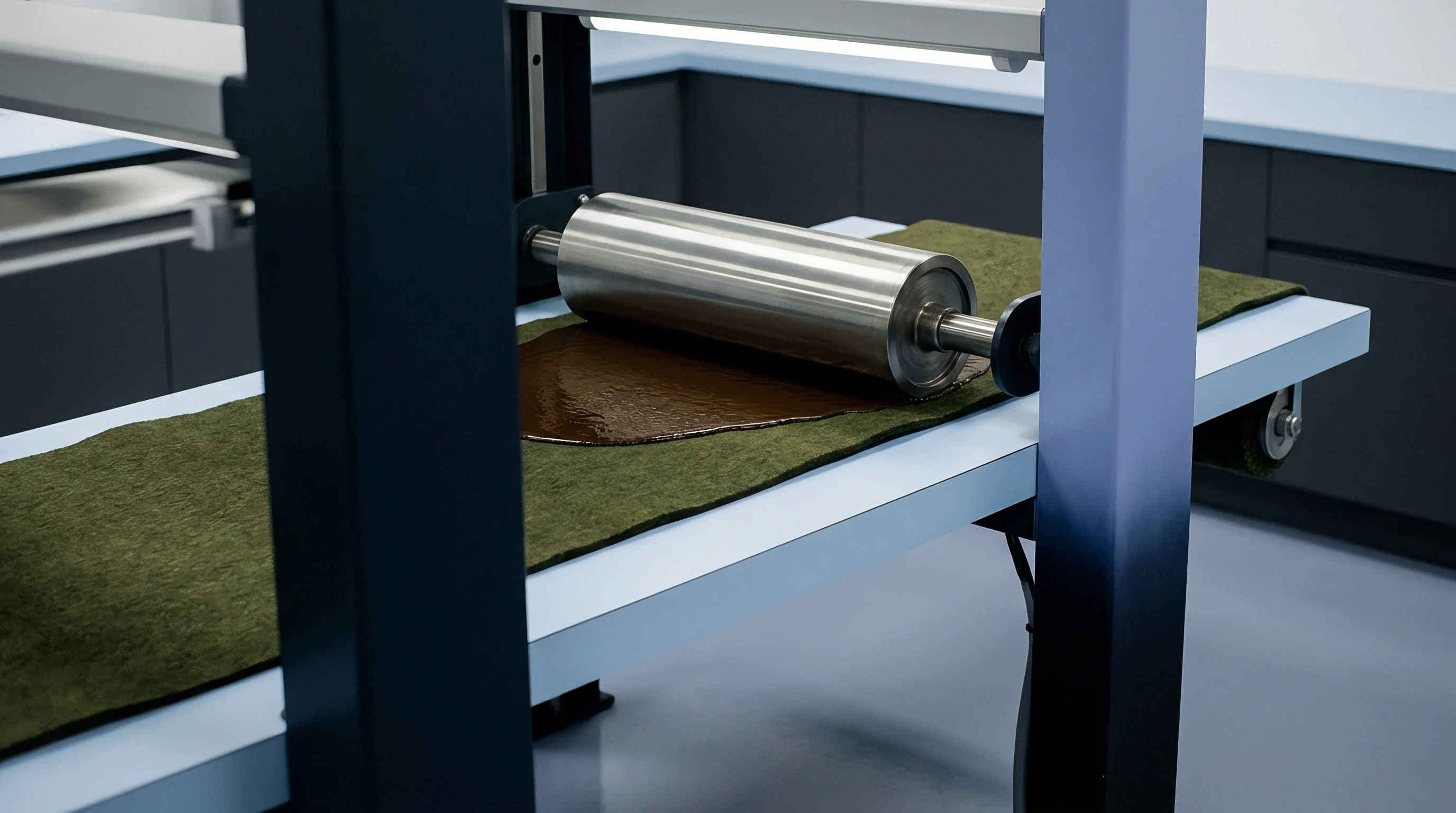
Heat alters fluid resistance instantly. A coating color tested at 22 degrees Celsius displays an apparent viscosity significantly higher than the same batch tested at 25 degrees Celsius. Water circulation jackets and Peltier thermoelectric elements stabilize the measuring vessel within narrow thermal bands during testing.
Mineral oils foul silicone bobs. Standard Brookfield low-shear testing uses a thermal jacket surrounding a 600-milliliter beaker, while high-shear instruments circulate temperature-conditioned water directly through the outer steel cup jacket. Thermal equilibrium across the entire metallic assembly guarantees that certified reference fluids match their laboratory calibration certificates.

Thermal Control Mechanisms and Viscosity Drift
Jacketed thermal housings connect to external circulating baths with temperature control stability within 0.05 degrees Celsius. Certified calibration oil S600 exhibits a kinematic viscosity drift of 0.82 percent per degree Celsius shift away from 25.0 degrees. This figure rests on ASTM D445 certified calibration sheets established across five-point capillary kinematic tests at 20 degrees Celsius and 25 degrees Celsius.
Using a synthetic polyalphaolefin fluid instead of polydimethylsiloxane shifts that coefficient closer to 0.65 percent per degree Celsius. Temperature shifts invalidate certified values.
Certified calibration oil S600 exhibits a kinematic viscosity drift of 0.82 percent per degree Celsius shift away from 25.0 degrees.
A similar thermal runaway phenomenon appears in automotive transmission fluid testing, where extreme shear thinning masks internal gear boundary friction. On the paper coating laboratory bench, the same physics distorts fluid readings. High shear rates generate internal friction that raises coating color temperatures by three to seven degrees within ten seconds of continuous rotation.
Pre-tempering the sample prior to spindle immersion prevents thermal shock across delicate internal torque springs.
Operational thermal control follows these specific equipment inspection points:
- Thermal equilibrium verification confirms that both the calibration oil and stainless steel geometry sit within 0.1 degrees Celsius of the target test setting.
- Circulation fluid filtration prevents particulate buildup inside jacket channels, preserving steady convective heat transfer across the test cell.
- Sensor probe immersion depth matches the active fluid layer to eliminate ambient air thermal gradients from corrupting baseline resistance figures.
Equipment manufacturers frequently claim that rapid thermal recovery systems negate the need for pre-test fluid tempering cycles.

Tolerance
Certified Newtonian silicone standards define the allowable variance bands for laboratory viscometers before production slurries enter testing. Calibration procedures verify two independent physical systems: the mechanical torsion spring measuring resistance torque, and the dimensional integrity of the bob and cup assembly. High shear distorts uncalibrated springs.
Torque spring constants change over time due to cyclical mechanical fatigue, chemical corrosion from cleaning solvents, and accidental over-torquing during high-solids testing. Verifying spring linearity involves applying calibrated deadweights across a balanced pulley to confirm that angular deflection corresponds linearly with applied dyne-centimeter loads.

Stepwise Torque Spring Verification Sequence
Laboratories maintain instrument precision through a structured verification sequence, eliminating cumulative mechanical errors before analyzing production batches:
- Thermal stabilization check holds the cup and bob assembly at exactly 25.0 degrees Celsius, because a half-degree error invalidates the oil certification.
- Deadweight spring qualification verifies rotational transducer linearity across five load increments, where unspotted hysteresis causes systemic calibration offsets.
- Newtonian oil run measures instrument deflection at calibrated rotational velocities, proving whether mechanical friction has degraded internal bearings.
- Instrument constant derivation compares measured torque against the certified fluid viscosity, establishing the mathematical multiplier for subsequent mill coatings.
Take a high-shear Hercules viscometer fitted with Bob A, having an inner bob radius of 1.95 centimeters, a cup radius of 2.00 centimeters, an effective bob height of 5.00 centimeters, and a nominal spring factor of 1.000 dynes per centimeter deflection. The deadweight calibration uses precision weights hung from a 3.00-centimeter radius calibration wheel. Applying a 100.0-gram mass produces a downward force of 98,100 dynes under standard gravity.
Multiplying this force by the 3.00-centimeter pulley radius yields an applied torque of 294,300 dyne-centimeters. A certified spring with a factor of 1.000 dynes per centimeter deflection must register exactly 29.43 centimeters of scale deflection. An observed deflection of 28.20 centimeters indicates spring stiffening, demanding an adjusted spring factor calculation of 1.044 dynes per centimeter.
Following spring verification, the technician loads Cannon certified reference oil S600 into the cup. The oil carries a certified dynamic viscosity of 1,250 mPa·s at 25.0 degrees Celsius. Running Bob A at 1,100 revolutions per minute establishes an annular shear rate of 4,400 reciprocal seconds.
Certified oils drift under shear. The theoretical torque generated by this fluid resistance matches the certified viscosity multiplied by the instrument geometric constant and rotational velocity. If the calculated apparent viscosity from the instrument scale reads 1,310 mPa·s, the instrument displays an error of plus 4.8 percent.
A variance exceeding five percent demands complete disassembly, bearing inspection, and recalibration.
| Standard Oil Grade | Nominal Viscosity (mPa·s) | Temperature Coefficient (%/°C) | Allowable Tolerance Band (%) | Verification Interval (Days) |
|---|---|---|---|---|
| Cannon N100 | 120 | 0.72 | ±2.0 | 30 |
| Cannon S600 | 1,250 | 0.82 | ±2.0 | 30 |
| Brookfield 5000 | 5,000 | 0.91 | ±1.0 | 14 |
| Hercules Hi-Shear Oil B | 42 | 0.65 | ±2.5 | 7 |
| Paragon ISO VG 460 | 460 | 0.78 | ±2.0 | 30 |
| Methods note: Kinematic and dynamic viscosity certified in accordance with ASTM D445 and ISO 3104 test specifications. | ||||
Turbulence masks true plastic viscosity. The desk cannot fully defend the mill-floor claim that a 3 mPa·s low-shear Brookfield drift consistently produces a 1.2 gram per square meter coat weight variation on rod coaters. Operating under that uncertainty, the buyer writes an explicit goods-in coat weight tolerance of plus or minus 0.5 grams per square meter directly into the reel delivery specification rather than relying on the mill’s rheology certificate.
The unresolved problem remains whether synthetic hydrocarbon reference oils provide better long-term chemical compatibility with fluoropolymer-coated geometries than standard polydimethylsiloxane fluids.
Defect
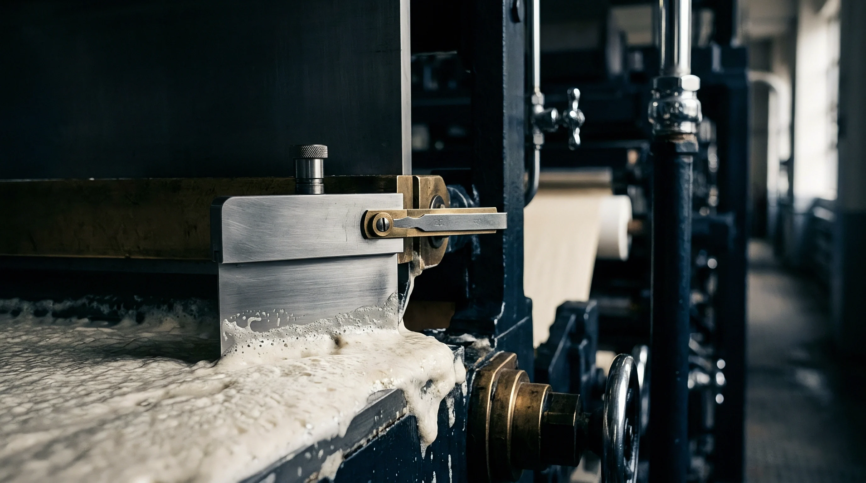
Viscosity variations directly alter blade coater hydrodynamic lift, shifting dry coat weight distribution across the paper machine web. When coating color enters the converging zone ahead of a trailing doctor blade, dynamic pressure forces the blade tip away from the sheet surface. Coater speeds amplify formulation errors.
An uncalibrated high-shear viscometer that underreports slurry dilatancy leads operators to formulate coating colors that jam beneath the blade. This particulate jamming lifts the steel blade, depositing heavy coat weight bands that cause uneven binder migration, web blistering in gas dryers, and calender blackening.

Blade Bleeding and Coating Streaks
Excessive high-shear viscosity forces pigment agglomerates toward the trailing blade edge, creating gouges in the wet film. Off-ratio coatings bleed past blades. When a shear-thickening slurry encounters the blade nip, localized shear stress exceeds the yield strength of the pigment network.
Particles stall behind the blade edge, accumulating until trailing whiskers and stalagmites spit onto the moving web. Dry solids content drives dilatancy. Low-shear viscometer drift creates opposite defects: formulations with deficient low-shear viscosity penetrate too deeply into open paper pores, causing binder depletion at the surface, poor ink holdout, and flaking during offset printing.
A coating color that thickens under blade nip compression generates scratches along the raw stock surface.
Web breaks at the coater nip cost mills thousands of dollars in lost throughput and broke repulping expenses. When coating colors bleed along the trailing blade edge, adjusting pigment dispersion takes precedence over increasing backing roll pressure.