Electro-Mechanical Feedback Calibration for Micro-Stepping Impression Control during Speed Transitions on Multi-Ply Board Presses
Dynamic micro-stepping impression control compensates for strain-rate stiffness shifts during press speed ramps, preserving multi-ply board caliper and strength.
Stiffness
Viscoelastic Dynamic Response in Multi-Ply Structures
Multi-ply board structures exhibit time-dependent deformation under mechanical load that departs sharply from isotropic paperboard behavior. When solid bleached sulfate or folding boxboard passes through an impression nip, the top chemical pulp plies, mechanical middle plies, and coated back layers experience severe compressive strain rates. At production speeds exceeding four hundred meters per minute, the dwell time within a five-millimeter nip width drops below seven hundred microseconds.
Under these fast impulse durations, the internal moisture distribution and porous matrix of mechanical fibers generate transient hydraulic resistance. The board behaves stiffer at high line speeds than at crawl speed because trapped moisture and air cannot evacuate the web matrix during microsecond impression cycles.
Press acceleration profiles alter this dynamic equilibrium continuously. Machine velocity shifts from make-ready speed at fifty meters per minute to full operating speed over a thirty-second linear ramp change the compressive strain rate by an order of magnitude. At lower speeds, the board caliper compresses further under a fixed mechanical gap setting because the viscoelastic fibers have sufficient time to relax.
As the press speeds up, the dynamic yield point rises. The higher strain rate increases the effective elastic modulus of the middle mechanical plies, forcing the impression cylinder to transfer greater mechanical peak force into the board coating layers. This velocity-dependent stiffness shift causes dot gain variance, mottling, and inconsistent varnish transfer across the acceleration phase.

Mechanical Compliance across Drive Train Elements
Preserving a uniform impression gap across dynamic speed shifts requires managing the structural deflection of the press framing, eccentric bearings, and loaded cylinders. Print cylinder bending follows classical beam theory, where central deflection varies directly with nip loading and the cube of the cylinder span. Static calibration settings configured during initial make-ready neglect the dynamic torque changes and centrifugal forces occurring within high-speed speed transitions.
| Line Speed (m/min) | Impression Strain Rate (s⁻¹) | Dynamic Caliper Compression (μm) | Bearing Eccentricity Deflection (μm) | Required Micro-Step Offset (μm) |
|---|---|---|---|---|
| 50 | 1,200 | 28.4 | 1.2 | 0.0 |
| 150 | 3,600 | 22.1 | 3.8 | -2.5 |
| 300 | 7,200 | 17.5 | 7.4 | -6.3 |
| 450 | 10,800 | 14.2 | 11.6 | -10.8 |
Gearing backlash and eccentric bearing clearances shift position as driving motor torque fluctuates during ramp cycles. High motor torque applied during rapid acceleration rotates the eccentric journal housing within its clearance envelope, lifting or sinking the impression cylinder position by several micrometers. Combined with cylinder shaft flexure, this mechanical displacement alters the effective impression depth.
Micro-stepping linear actuators attached to the eccentric bear the responsibility of adjusting the nip position in real time to counteract these structural shifts.
A thirty percent increase in line velocity reduces total nip dwell time sufficiently to elevate effective multi-ply board stiffness by twelve percent.
Sensors embedded in the load path must differentiate between mechanical frame flexure and actual board compression changes. When press frame expansion caused by drive-gear oil heating occurs alongside speed ramping, static mechanical presets fail completely. The physical displacement of the journal housings introduces position errors that exceed the target tolerance of fine halftone printing and high-definition blind embossing passes.
Failing to compensate for structural flexure during speed transitions crushes the internal fiber matrix of recycled chipboard middle plies during slow phases, permanently destroying structural stiffness and box compression strength on finished cartons.
Actuation
Closed-Loop Micro-Stepping Drive Mechanics
Precision micro-stepping systems convert electronic step pulses into precise rotational positioning of eccentric impression shafts. Standard hybrid stepper motors operating at two hundred full steps per revolution are driven using micro-stepping controllers that divide each full step into two hundred and fifty-six electrical sub-steps. This delivers fifty-one thousand two hundred discrete positions per motor turn, translating to sub-micron linear movements at the nip envelope.
High micro-stepping ratios reduce torque ripple and low-speed resonance, preventing mechanical vibrations from marking the wet ink film during speed shifts.
Real-time position regulation depends on fast electromechanical feedback. Piezoelectric quartz transducers mounted directly behind the impression bearing blocks measure force variations across the nip width at kilohertz sampling frequencies. Optical linear encoders attached to the actuator slideways provide absolute position verification, closing the control loop.
When line speed increases, the control software calculates the expected fiber-stiffness change and instructs the micro-stepping driver to retract the eccentric shaft by a calculated distance, maintaining constant nip pressure.
Hysteresis Mitigation and Closed-Loop Control Algorithms
Mechanical backlash in worm gears and lead screws degrades position accuracy whenever the micro-stepping actuator reverses direction. Hysteresis curves recorded on impression adjustment assemblies show positioning lag ranging from three to eight micrometers when switching from extension to retraction. Compensating for this mechanical lag requires directional offset algorithms programmed directly into the drive controller logic.
- Quadrature Encoder Alignment locks the electrical zero point of the micro-stepping driver to physical linear positions, eliminating cumulative step-loss errors over extended production shifts.
- Backlash Pre-Compensation Loop applies a temporary pulse-burst over-shoot during actuator reversal, pulling mechanical gear teeth into immediate contact before settling at the target position.
- Proportional-Integral-Derivative Velocity Feedforward anticipates impression force variations using real-time line encoder feedback, adjusting micro-step pulses before board density changes register at the load sensor.
- Thermal Compensation Matrix adjusts linear step counts against temperature readings from thermocouples embedded on the eccentric bearing blocks, compensating for thermal expansion of press side frames.
Driver current control dictates position stability under heavy load. Micro-stepping motors lose holding torque as rotational pulse frequencies rise during fast corrections. Pulse-width modulation current drivers must increase voltage supply dynamically to overcome motor winding inductance, maintaining motor holding torque against heavy nip reaction forces.
Stepper motor torque degradation causes step skipping under high impression forces, destroying calibration profiles.
Uncalibrated actuators driven by open-loop pulse trains inevitably slip under heavy mechanical loads, leading line operators to claim that micro-stepping mechanisms cannot maintain physical registration on heavy multi-ply board grades.

Tension

Web Acceleration Dynamics and Inter-Nip Strain
Web tension shifts during press speed changes disrupt board caliper before the sheet reaches the printing or embossing unit. Acceleration increases web drag across stationary turn bars, friction guides, and infeed tension rolls. Multi-ply cartonboard subjected to fluctuating longitudinal strain exhibits Poisson contraction, where tensile stress along the grain direction causes slight thickness reduction and cross-grain narrowing.
A sudden tension spike during line acceleration reduces web thickness by up to three micrometers before impression contact occurs.
Standard ISO 12647 surface tolerance parameters demand that impression pressure variations stay within a four-micrometer window across full speed transition cycles.
Inter-nip strain coupling complicates impression control on multi-unit board presses. Variations in speed between adjacent printing units stretch or compress the web span between them. If unit two runs at a fractional percentage higher surface velocity than unit one during a speed ramp, the longitudinal tension in the intervening span escalates rapidly.
This tension spike alters the surface shear forces within the nip, shifting ink transfer behavior and mechanical dot gain independently of pure radial impression force.
What Dynamic Variables Disrupt Impression Equilibrium during Line Acceleration?
Speed transitions disturb four interconnected physical variables across the impression zone simultaneously:
- Hydrodynamic Ink Film Resistance increases with surface velocity, generating higher hydraulic separation forces within liquid ink films that push the printing plate and board substrate apart.
- Centrifugal Cylinder Expansion expands print cylinders and sleeve mandrels slightly at top press speeds, narrowing the physical impression gap between cylinders.
- Elastic Recoverability Window narrows as dwell time decreases, preventing thick board plies from expanding back to nominal caliper between consecutive print nips.
- Boundary Layer Air Entrainment introduces an air film between the board web and smooth impression rolls at elevated line speeds, altering friction coefficients and web tracking stability.
Decoupling these transient factors requires active feedback loops capable of isolating tension-induced caliper changes from viscoelastic board responses. Line acceleration profiles must integrate web tension sensor inputs directly into the micro-stepping control matrix. By modifying the step correction curve based on measured web tension, the press control system maintains consistent ink transfer mechanics across the operating spectrum.
How far adaptive feedback algorithms can predict localized density inconsistencies in low-grade recycled board cores during rapid acceleration remains a subject of ongoing investigation among packaging machinery designers.
Thresholds
Empirical Calibration Methods and Step-Response Protocols
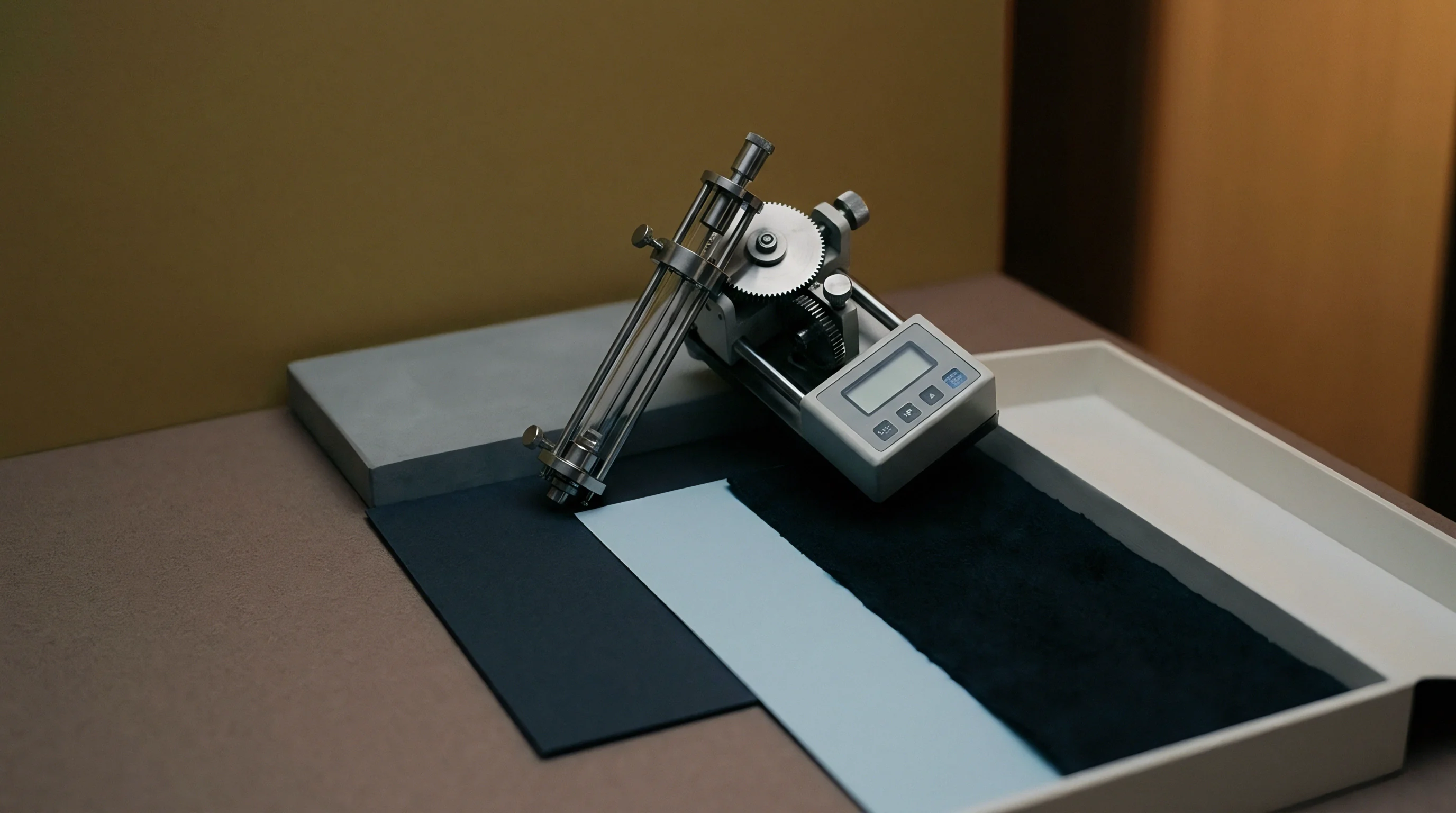
Establishing accurate micro-stepping response profiles demands rigorous physical calibration protocols. Calibration begins with static zeroing using piezoresistive surface contact strips placed between the impression cylinder and a non-compressible steel reference gauge. The micro-stepping motor drives the eccentric housing forward in single-step increments until the contact array detects uniform pressure across the entire face length.
This establishes the true mechanical origin point, removing mechanical play from the actuator linkage.
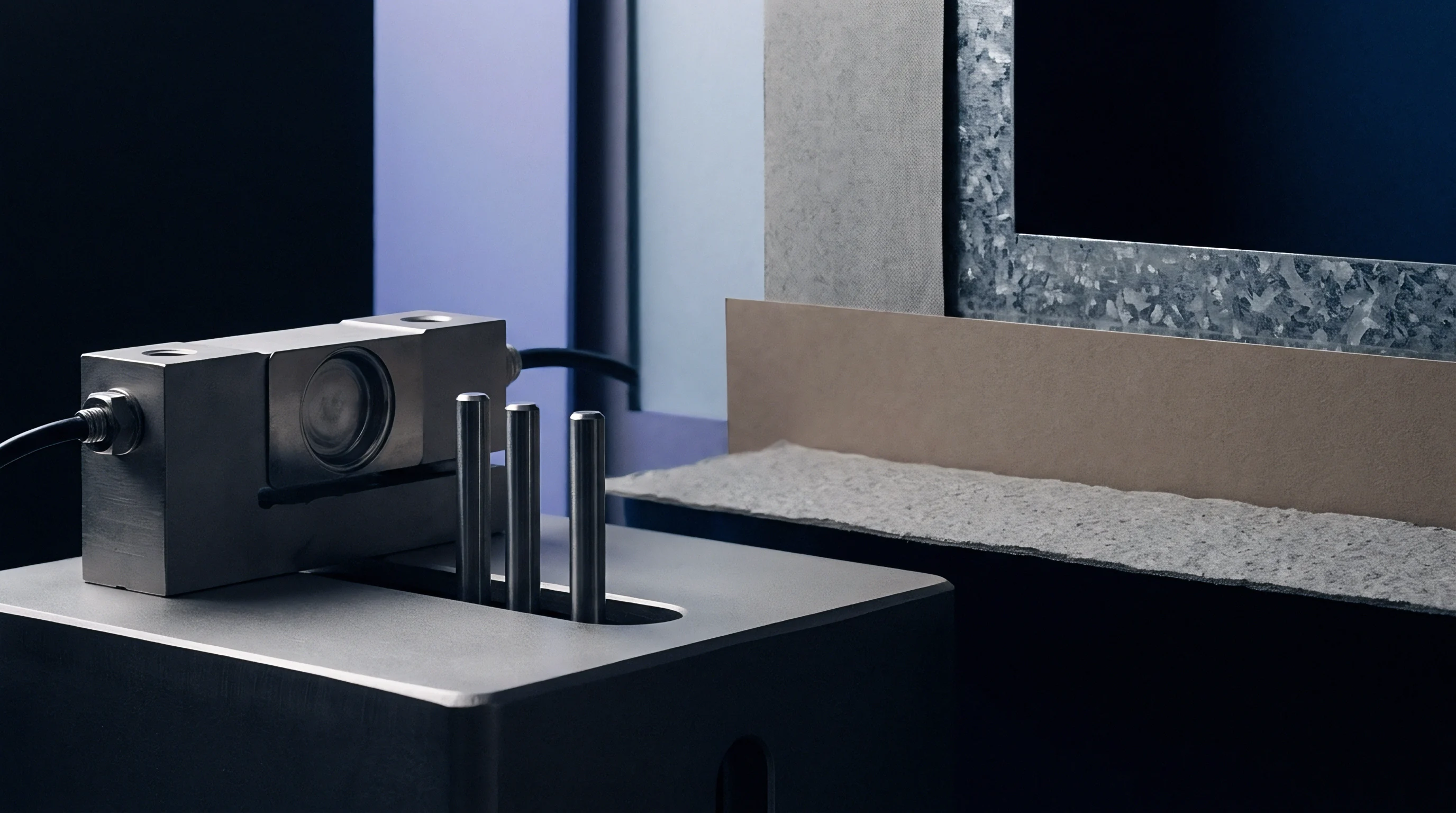
Dynamic step-response mapping follows static zeroing. The press runs at baseline speed while step-change commands are sent to the micro-stepping controller. Piezoelectric load cells measure the rise time, overshoot, and settling time of the impression force.
The damping ratio of the system is tuned by adjusting the controller acceleration parameters until the impression force reaches ninety percent of target value within fifteen milliseconds without exceeding peak force limits that crush board fibers.
Physical verification demands continuous testing across line speed ramps. Calibration procedure follows a strict sequential routine during machine qualification:
- Mount high-frequency piezoelectric load sensors across the press cylinder length at operator side, center, and drive side locations.
- Zero the electronic signal conditioners with the impression cylinder fully retracted at ambient temperature.
- Accelerate the press empty from crawl speed to maximum operating speed at a uniform acceleration rate of five meters per second squared to capture background mechanical noise and centrifugal expansion curves.
- Pass reference 300 gsm solid bleached sulfate board through the nip while executing incremental three-micrometer micro-step offset adjustments every five seconds.
- Record real-time impression force profiles and map sensor data against linear motor encoder readings to generate an automated correction matrix.
- Measure print density, dot gain, and board caliper on pulled samples using spectrophotometers and digital micrometer gauges to verify physical target compliance.
Step-response tuning must account for structural hysteresis. Step corrections applied during acceleration profiles must follow a distinct curve from those applied during deceleration ramps. Retracting the impression roll during speed reduction requires slightly larger step pulse counts to overcome internal drive gear friction compared to pushing the cylinder forward during acceleration.
Comparative Calibration Matrix and Performance Metrics
Static impression setting approaches produce unacceptable product variation during press ramp phases. Automated micro-stepping impression control maintains tight control over structural packaging metrics across complex speed transition cycles.
| Performance Parameter | Fixed Mechanical Setting | Open-Loop Micro-Stepping | Closed-Loop Piezo Feedback |
|---|---|---|---|
| Caliper Loss on 400 gsm FBB (μm) | 18.5 ± 3.2 | 8.2 ± 1.5 | 2.1 ± 0.4 |
| Dot Gain Variation (50% Tint) | +8.4% | +3.1% | +0.6% |
| BCT Strength Reduction (%) | 14.2% | 5.8% | 1.1% |
| Make-Ready Ramp Waste (Sheets) | 450 | 180 | 35 |
| Correction Latency (ms) | Manual / None | 120 | 8 |
Closed-loop micro-stepping feedback reduces internal ply crush significantly compared to static gap methods. By maintaining precise impression forces across all press speeds, the structural integrity of the cartonboard plies remains intact. This translates directly into higher top-load strength for finished folded cartons made from converted board.
Calibrating micro-stepping feedback loops against dynamic board response eliminates make-ready waste generated during press acceleration phases.
Optimal calibration requires mapping every board grade individually because fiber compositions alter viscoelastic recovery characteristics.


Penalty
Commercial Consequences of Board Over-Compression
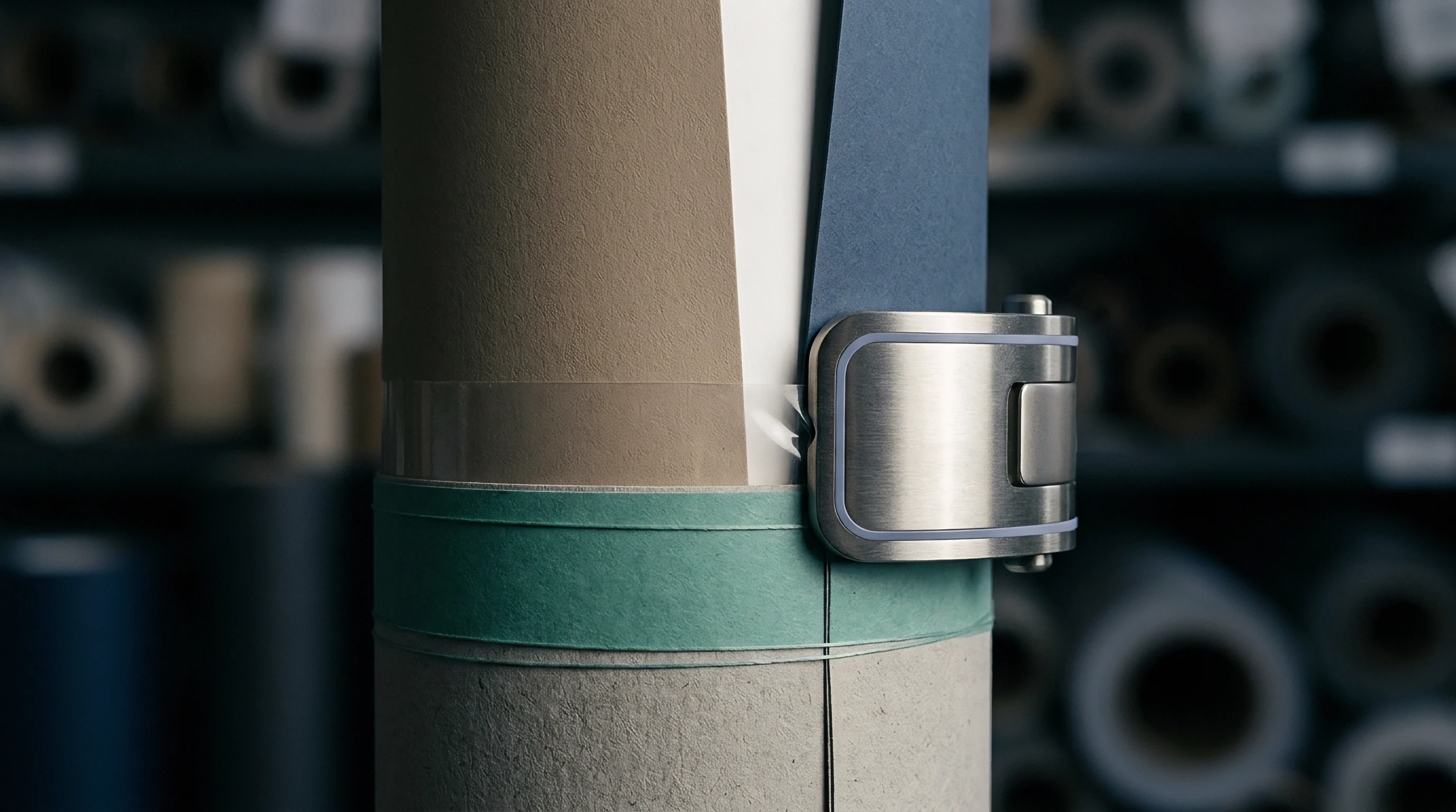
Crushing multi-ply board fibers through uncompensated impression force inflicts direct financial losses on converting operations. Multi-ply packaging structures rely on the thickness and density of middle mechanical or recycled plies to deliver bending stiffness. Bending stiffness scales with the cube of board caliper.
Losing five percent of board caliper due to excessive nip pressure during press acceleration ramps reduces structural bending stiffness by nearly fifteen percent.
Weakened board fails downstream performance requirements. Folded cartons produced from over-compressed board exhibit reduced Box Compression Test ratings, leading to carton collapse during automatic stacking and pallet transport. Packaging converters facing strict performance specifications must increase nominal paperboard basis weight to compensate for caliper destroyed during printing, adding raw material costs across the entire contract volume.
Financial Analysis of Speed-Transition Spoilage
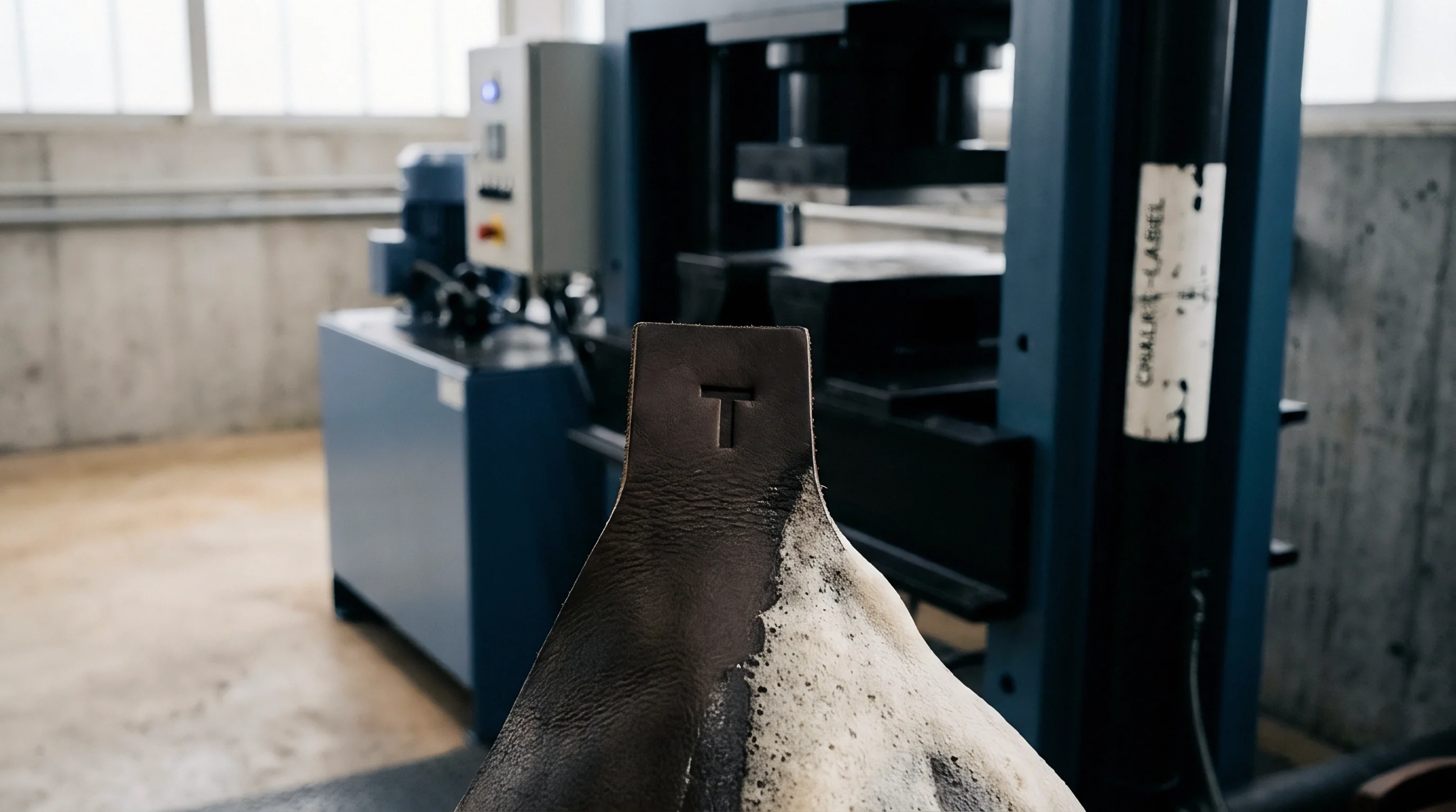
Make-ready and ramp-up waste directly erodes job profitability. During speed acceleration from crawl to target velocity, uncalibrated presses generate out-of-spec sheets that must be rejected. Consider a representative high-volume converting job running on an eight-hundred-millimeter multi-ply board press running 350 gsm Folding Boxboard priced at twelve hundred dollars per metric tonne.
A five percent reduction in multi-ply board caliper degrades structural carton bending stiffness by nearly fifteen percent.
Assume a press speed transition duration of forty seconds, occurring eight times per shift during roll changes, ink maintenance, and wash-up cycles. On an uncalibrated machine producing four hundred ruined sheets per transition, total ramp waste equals three thousand two hundred sheets per shift. Over a three-shift daily operating schedule, this equates to nine thousand six hundred waste sheets per day, or approximately two point seven metric tonnes of discarded board.
At twelve hundred dollars per tonne, uncompensated impression calibration during speed ramps costs thirty-two hundred dollars per day in raw board waste alone, excluding wasted ink, energy, and press running time.
Modulated eco-tax fees and extended producer responsibility packaging schemes penalize heavy packaging designs. When converters increase board basis weight by twenty grams per square meter to offset caliper lost to mechanical fiber crush, annual packaging waste fees rise proportionally. Recyclability grading schemes also discount fiber value when crushed layers absorb excessive ink binders into fractured middle plies, reducing reclaimed fiber yield during pulping operations.
Automated micro-stepping impression calibration protects both the physical board matrix and the unit economics of the printing pass. Protecting board caliper during velocity transitions preserves carton structural performance, keeps waste rates within tight technical targets, and prevents raw material over-specification across high-speed packaging runs.