Compensating Vector Artwork for Thermal Growth in CNC Brass Embossing Engraving
Prepress downscaling contracts vector artwork to compensate for predictable brass die thermal expansion at hot stamping press operating temperatures.
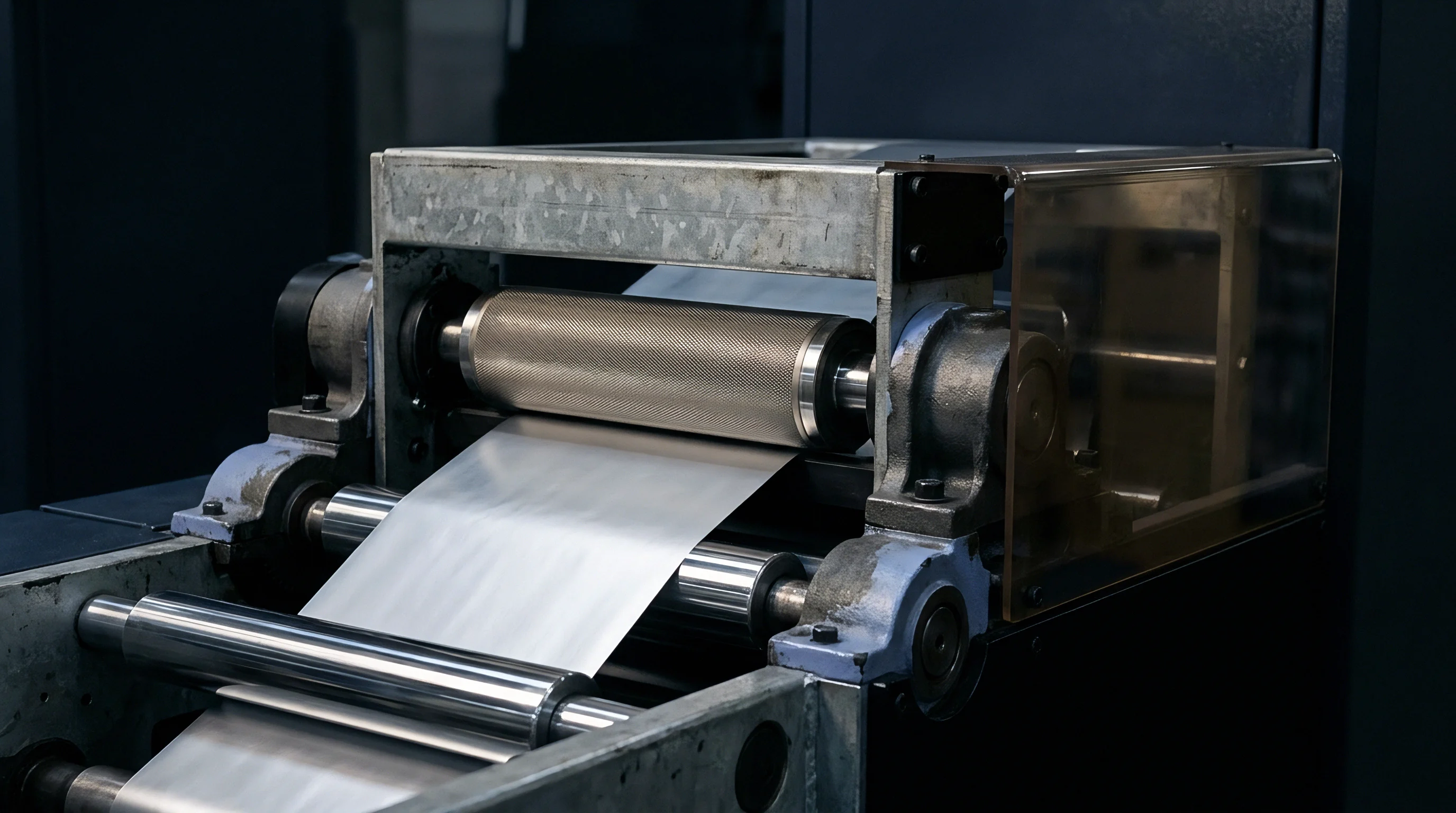
Expansion
Brass alloys expand continuously when subjected to elevated temperatures on a heated stamping chase. Free-cutting leaded brass grades CZ121 and C36000 exhibit a coefficient of thermal expansion between 19.0 and 20.5 micrometers per meter per kelvin at standard atmospheric conditions. CNC engraving tools cut die cavities into cold metal blocks at an ambient room baseline near 20 degrees Celsius.
Hot foil stamping and combination embossing presses operate between 110 and 160 degrees Celsius depending on substrate weight, foil release chemistry, and press dwell time. This operational temperature jump creates a predictable physical displacement across the face of the plate.
Platen heaters transfer thermal energy through the steel chase directly into the back of the brass block. Dimensional growth occurs outward from the mechanical locking point or central centroid of the die. Across a large-format sheet measuring 740 millimeters along the gripper margin, an uncompensated temperature rise of 110 degrees Celsius expands the brass boundary by over 1.5 millimeters.
Paperboard substrates do not match this dimensional change; elevated temperatures evaporate internal fiber moisture, causing paper stock to shrink slightly while the brass die expands.
| Brass Alloy Grade | Expansion Coefficient (um/m K) | Base Length (mm) | Delta T (C) | Linear Shift (mm) |
|---|---|---|---|---|
| CZ121 / CW614N free-machining | 19.5 | 500 | 90 | 0.8775 |
| CZ121 / CW614N free-machining | 19.5 | 740 | 110 | 1.5873 |
| C36000 high-leaded brass | 20.5 | 500 | 90 | 0.9225 |
| C36000 high-leaded brass | 20.5 | 740 | 110 | 1.6687 |
Press operators attempting to align an uncompensated hot die against cold offset-printed sheets encounter severe register creep at the sheet edges. Center artwork aligns accurately, but outer elements drift outward, punching through print boundaries and exposing unprinted paper margins. Mechanical adjustments at the press chase cannot cure this geometric mismatch.
Adjusting chase lockups merely repositions the register error without reducing the overall distance between outer relief cavities.
Dimensional drift scales in direct proportion to plate size and thermal elevation. Larger press formats amplify perimeter displacement, converting tiny material properties into obvious visual defects across finished folding cartons. Die structural integrity remains stable, yet geometric fidelity collapses relative to the printed sheet.
Failure to compensate vector geometry for thermal swelling leaves press operators with misregistered sheets, destroyed foil boundaries, and rejected job lots that force complete die re-engraving at the converter’s expense.

Vector
Prepress operators compensate for thermal growth by downscaling bezier curves and path coordinates inside vector geometry prior to machine toolpath generation. Mathematical reduction factors derive from the linear thermal expansion formula applied across two orthogonal axes. Scale adjustments take place around a designated origin point, typically matching the press lay edge or central sheet centroid.
Linear thermal scaling factors apply an inverse percentage factor to vector coordinates based on the anticipated delta between room engraving temperature and hot press operation.
Calculating the precise scaling factor k requires dividing the cold baseline dimension by the heated operational dimension. Formula calculations utilize the thermal expansion coefficient α and the temperature difference Δ T according to the expression k = frac11 + α · Δ T. Applied to vector lines, this formula contracts distance dimensions while preserving line weights, curve radii, and relative feature geometry.
Anisotropic physical conditions occasionally require asymmetrical scaling factors along orthogonal directions. Heated bed platens sometimes exhibit directional thermal gradients caused by edge loss or localized heating elements. Press draw force and paper moisture loss along the grain direction create unequal shrinkage vectors across the sheet length versus width.
Prepress algorithms account for this by applying differential multipliers kx and ky independently across horizontal and vertical coordinates.
| Target Temp (C) | Delta T (K) | Linear Factor (k) | Scale Setting (%) | Dimensional Delta (%) |
|---|---|---|---|---|
| 100 | 80 | 0.998442 | 99.8442 | -0.1558 |
| 120 | 100 | 0.998054 | 99.8054 | -0.1946 |
| 130 | 110 | 0.997860 | 99.7860 | -0.2140 |
| 150 | 130 | 0.997471 | 99.7471 | -0.2529 |
A worked example demonstrates prepress calculations for a folding carton die measuring 700 millimeters wide, scheduled on a press operating at 130 degrees Celsius. Engraving room temperature measures 20 degrees Celsius, yielding a Δ T of 110 kelvin. Using an expansion coefficient of 19.5 × 10⁻⁶ /K, the expansion factor equals 0.002145.
Dividing original dimensions by 1.002145 generates a scaling percentage of 99.7860 percent. Prepress geometry contracts from 700.000 millimeters down to 698.502 millimeters in software prior to outputting toolpaths.
Coordinate transformation relies on fixed anchor points. Centroid scaling retains central position while drawing outer edges inward. Gripper-edge scaling fixes the front register line while contracting artwork toward the gripper margin, matching press register side-lay behavior.
Selecting the incorrect origin point during vector processing shifts the entire artwork block off-center on press, negating the accuracy of the mathematical scaling calculation.
- Anchor Centroid Placement establishes the exact mathematical center from which vector node scaling calculations contract outer line coordinates equally toward the middle.
- Differential Axis Compensation modifies horizontal and vertical vector dimensions using unique percentage multipliers to correct for non-isotropic paperboard shrinkage.
- Feature Width Protection preserves minimum stroke weights and small text walls during artwork contraction, ensuring narrow engraving tools fit inside fine line geometry.
- Node Density Rationalization simplifies complex bezier curves before scaling to prevent mathematical rounding errors along high-density vector paths.
Vector line weights require careful verification following downscaling operations. Reducing vector artwork geometry contracts wall thicknesses, narrow spaces, and fine relief lines alongside overall outer dimensions. Micro-embossing patterns and fine text strokes running near minimum tool diameter limits risk collapsing below the cut threshold of 0.10-millimeter engraving cutters.
Prepress software must execute line-weight restoration filters after scaling to hold minimum trench widths, ensuring ball-nose end mills pass cleanly through relief paths.
Toolpath generation software processes scaled vector geometry to produce machine control commands. Modern CAM systems calculate cutter paths directly from downscaled vector nodes rather than applying scaling multipliers to post-processed G-code. Direct node processing eliminates cumulative rounding errors across multi-axis roughing and finishing cycles.
Die suppliers frequently argue that press chase expansion counteracts brass plate growth, claiming pre-compensation distorts original brand artwork files.

Draft
Vertical relief depth in brass embossing dies changes under thermal expansion alongside horizontal dimensions. Linear growth along the z-axis thickens the plate, increasing relief cavity depth slightly. Flank angles cut into die walls guide paper fibers into deep embossing cavities without shearing board surfaces.
Thermal growth along the z-axis alters wall slopes, changing effective draft angles relative to male counter-dies.
3D sculpted dies feature varied relief depths across organic, rounded, or textured surfaces. Standard draft angles run between 30 and 45 degrees relative to the vertical plane. Heating causes brass material to swell perpendicular to cavity walls, reducing clearance gaps inside tight relief channels.
Toolpath programs must compensate for flank geometry by widening cavity bases and adjusting steep bevel angles on female dies.

When Does Uncompensated Brass Growth Destroy Register?
Register destruction occurs when cumulative outer-edge displacement exceeds half the width of the printed outline or foil line. Standard sheet-fed hot stamping presses maintain mechanical registration tolerances within 0.05 millimeters. Uncompensated brass expansion on a 600-millimeter die running at 130 degrees Celsius creates over 1.28 millimeters of dimensional shift at outer die edges.
Register breaks completely across outer press zones within minutes of reaching thermal equilibrium.
- Record ambient engraving room temperature and measure raw brass plate dimensions using calibrated vernier calipers.
- Obtain confirmed operating temperature specifications and target press run speeds from the finishing line manager.
- Calculate axis-specific scaling factors using the verified thermal coefficient for the selected brass alloy batch.
- Apply downscaling transformations in prepress software using the designated press registration anchor point as origin.
- Audit scaled vector line widths using digital calipers inside CAD software to confirm cutter accessibility for minimum tool radii.
- Generate finishing toolpaths and mill the brass die plate using high-speed CNC engraving equipment under temperature-controlled flood coolant.
Draft angle clearance must exceed three degrees per side to prevent paperboard tearing as thermal expansion narrows female die cavity channels.
Deep-draw embossing profiles present severe clearance challenges. Heat transfers quickly into paperboard fibers upon contact, causing local moisture flashing. Moisture loss reduces board caliper and stiffness while the brass die cavity narrows under heat expansion.
Draft angles cut too steep wedge paper fibers against die walls, producing visible surface scuffing, foil fracture, or sheet jamming on press delivery belts.
Engraving depth adjustments require isolated z-axis scaling inside 3D CAD modeling software. Multi-level vector graphics undergo surface mesh contraction while maintaining fixed floor depth datum levels. High-precision laser depth scanners verify relief profiles before shipping plates to press rooms.
Unresolved technical debates persist regarding whether variable z-axis expansion across sculpted multi-level dies alters perceived light reflection angles on textured foil surfaces.

Counter
Male counter-dies mounted on press platens must match female brass die dimensions precisely at operating temperature. Counter-dies manufactured from resin, fiberglass, or vulcanized board exhibit thermal properties distinct from brass. Phenolic board counter-dies expand at rates differing substantially from copper or brass plates.
Matching male and female components requires careful control over temperature conditions during counter creation.
Pouring quick-setting resin counters directly against cold brass plates creates immediate dimensional misalignment once the press reaches operating heat. The cold-cast resin counter retains room-temperature dimensions, while the brass die expands under platen heaters. Press operators must warm the brass die plate to full production temperature before casting or molding counter-die matrices on press.
Counter-die materials must undergo thermal conditioning at target press temperatures before final male force curing occurs.
- Epoxy Resin Counters poured directly against pre-heated brass dies achieve exact dimensional alignment by curing at full operating temperature.
- Fiberglass Counter Boards require pre-stretching and thermal soak cycles prior to impression setting to eliminate heat-induced warp.
- Micro-Embossing Matrix Plates must utilize brass-matched metallic backings to ensure identical linear expansion rates across micro-structure fields.
- Pre-molded Phenolic Forces demand prepress downscaling matching the exact percentage applied to female brass vector files.
Press make-ready procedures require controlled temperature stabilization intervals. Platen heaters must soak the brass die and chase assembly for at least 45 minutes before registering counter-dies. Fast bring-up cycles create steep internal thermal gradients, warping the plate and ruining male-female impression alignment across the bed.
Micro-embossing patterns featuring light-refracting line structures demand micro-step registration accuracy. Micro-grooves cut at spatial frequencies of 500 lines per millimeter cannot tolerate relative movement exceeding two micrometers between die and counter. Resin matrices molded against cold micro-embossing dies strip away fine line structures during initial hot press production passes.
Molding male counter forces against fully heat-stabilized brass dies eliminates registration creep across long packaging runs.
Settlement
Commercial contracts for high-volume packaging production assign clear financial responsibility for artwork preparation errors. Prepress vector scaling failure represents a direct tooling specification error rather than an acceptable press-room make-ready variation. When uncompensated vector files cause off-register stamping, the cost of scrapped sheet stock, lost press time, and replacement die machining falls upon the party supplying uncompensated artwork files.
Die replacement costs extend far beyond the raw metal charge and CNC machining hours. High-speed foil stamping presses carry hourly rate charges between 180 and 350 dollars. Holding a press idle while waiting for replacement brass dies destroys job profitability and disrupts scheduled converting sequences.
Scrap costs escalate rapidly when foil stamping operates as a secondary pass over expensive multi-color offset printed sheets.
Rejection of finished packaging lots due to thermal register drift occurs when outer-edge foil alignment strays beyond published tolerance limits.
A standard quality assurance clause in converting contracts specifies print-to-emboss register tolerances within plus or minus 0.15 millimeters across the full sheet format. Uncompensated brass expansion on large dies easily exceeds 1.5 millimeters, producing defect levels that trigger automatic rejection under ISO 2859-1 sampling protocols. Rejection forces complete job reprinting, hot foil re-stamping, and structural die cutting, multiplying financial loss across the supply chain.
Sourcing agreements establish explicit artwork handoff protocols between design agencies, packaging buyers, and die engravers. Specifications must state whether vector files represent cold artwork dimensions or fully compensated prepress geometry. Clear docket notations prevent double-compensation errors caused when both prepress departments and die engravers apply independent scaling factors to identical vector files.
Standard purchase contracts stipulate that vector artwork submitted for hot-stamping brass die production shall represent raw target dimensions, placing sole contractual obligation for thermal expansion compensation upon the die engraver’s prepress department under documented operating press parameters.