Calibrating Artwork Scaling Factors for Heated Platen Brass Chases
Calibrating artwork scaling factors offsets brass thermal expansion and substrate heat shrinkage to achieve exact register alignment on hot platen presses.

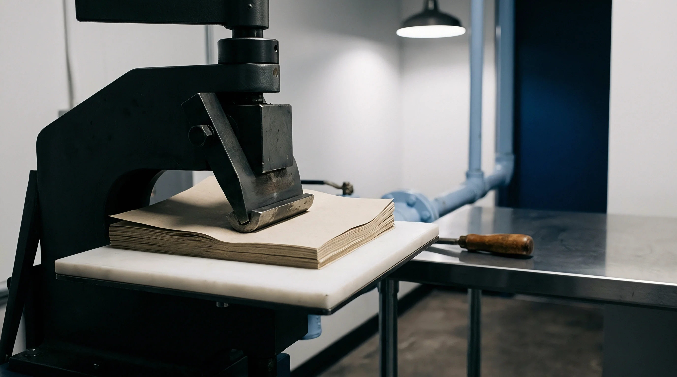
Expansion
Hot foil stamping and embossing on heated platen presses depend on controlling how brass dies expand under load. When artwork is engraved into a brass block at a room temperature of 20°C, the metal expands uniformly in all directions once locked in a chase and heated to working temperatures between 110°C and 160°C. Artwork cut at nominal size without allowance expands past the printed board boundaries, producing register drift, edge halos, and trapped air under the foil. Setting the correct scaling factor requires accounting for brass metallurgy, thermal expansion coefficients, and temperature distribution across the press platen.
Engraver’s brass consists mostly of leaded alpha-beta copper-zinc alloys like CuZn37, CuZn39Pb3, and CuZn40Pb2, which balance clean CNC machinability against the hardness needed for repeated platen impacts. The linear thermal expansion coefficient for these alloys ranges from 18.5 to 20.5 millimetres per metre-Kelvin across standard working ranges. Heating a 700 millimetre by 1000 millimetre brass die from a 20°C floor up to a stamping heat of 135°C grows its long axis by more than 1.6 millimetres.
In tight grid layouts or fine micro-embossing, leaving that shift unadjusted destroys registration at the outer die positions.
Linear dimensional expansion follows a direct mechanical relationship:
Delta L = L_0 x alpha x Delta T
Here, L_0 is the original artwork length at calibration temperature, alpha is the alloy’s linear thermal expansion coefficient, and Delta T is the temperature rise from engraving room to press operation. A die cut at 21°C and run at 140°C gives a Delta T of 119 Kelvin. At a typical coefficient of 19.3 x 10^-6 per Kelvin, every 100 millimetres of vector art stretches by 0.229 millimetres.
Across a wide-format chase, that elongation throws off multi-color foil overlays and blind embossing alignment against offset inks.
Thermal Physics of Copper Zinc Alloys
The microstructure of brass governs how the die expands under heat. Lead particles distributed throughout the metal act as internal lubricants during cutting, though they also subtly shift local heat transfer across the block. Thermal conductivity in CuZn39Pb3 averages about 115 Watts per metre-Kelvin at 100°C, which allows thin sections to reach thermal equilibrium fairly quickly.
Heavy solid dies, however, take longer to absorb heat, creating temporary thermal gradients while the press warms up.
Platen heaters transfer heat down through the upper bed and steel backing plates into the brass chase. That heat crosses several physical boundaries, each adding contact resistance. Air gaps from microscopic roughness or loose chase clamping lower local transfer rates, while outer edges lose heat to the room through radiation and convection.
Press controllers often drive perimeter zones harder to counter this edge loss, which creates uneven temperatures across the die face.
Brass dies heated to 135°C expand linearly by 0.222 percent relative to their ambient dimensions at 20°C.
These localized temperature differences change the actual expansion across a single large die. A center section running at 135°C expands according to its local Delta T, whereas outer margins at 142°C stretch further. The variance distorts what was a flat rectangular layout into a subtle barrel shape.
Artwork compensation must therefore reflect both average steady-state temperatures and the zone offsets set during setup.

Platen Temperature Gradients and Mounting Constraints
Lockup hardware sets rigid physical limits on die expansion. Steel chases secure brass dies with toggle clamps, thermal expander pins, or wedge locks. But steel has a lower expansion coefficient than brass ~ between 11.0 x 10^-6 per Kelvin and 12.5 x 10^-6 per Kelvin.
As the press bed heats up, the brass tries to expand faster than the steel pocket holding it, building up severe internal compressive stress if unconstrained.
When thermal expansion is blocked, heat turns into mechanical stress. If that force surpasses the yield strength of the hot brass, the die deforms slightly or bows away from the backing plate. Bowing in the center unevenly distributes impression pressure, depositing thick foil along the high crown and leaving faint, incomplete transfer around outer details.
Proper chase preparation leaves engineered expansion clearances around die perimeters or cuts expansion slots directly into large brass plates.
Unexpected die movement stems either from chemical impurities in commercial brass or from minor alloy batch variations that shift register over long runs.

Drift
Substrate behavior inside a heated platen press adds another layer of complexity to scaling. Paperboard and synthetic stocks are far from dimensionally stable under heat and pressure. As a sheet feeds between the heated upper chase and the lower impression platen, it faces sudden contact heat, high pressure, and rapid moisture loss.
Depending on fiber orientation, moisture levels, and coatings, the board can shrink, swell, or warp.
Cellulose fibers gain and lose moisture depending on ambient temperature and humidity. In an ISO 187 room kept at 23°C and 50 percent relative humidity, virgin folding boxboard rests at roughly 6 to 8 percent equilibrium moisture. Hitting a die plate heated to 130°C flashes off surface moisture almost instantly.
This rapid drying shrinks the paperboard matrix during the brief 80 to 250 millisecond impression dwell.
Substrate shrinkage works directly against die expansion: as the hot metal expands outward, the drying sheet pulls inward. These opposing movements magnify registration errors, meaning any prepress scaling formula has to combine metal growth and sheet shrinkage into a single geometric calculation.
Paper machines align pulp fibers primarily along the direction of travel, giving board distinct machine direction and cross-machine direction properties. When wood fibers lose moisture, they shrink mostly in diameter rather than length. As a result, cross-machine shrinkage under hot platen exposure is typically three to five times greater than machine-direction shrinkage.
| Substrate Grade | Grammage GSM | Dwell Time MS | Platen Temp C | MD Shrinkage Percent | CD Shrinkage Percent |
|---|---|---|---|---|---|
| Solid Bleached Sulfate SBS | 300 | 120 | 135 | -0.015 | -0.062 |
| Folding Boxboard FBB | 350 | 150 | 140 | -0.022 | -0.088 |
| Coated Recycled Board CRB | 400 | 180 | 130 | -0.031 | -0.115 |
| Uncoated Fine Paper | 120 | 90 | 120 | -0.045 | -0.160 |
| Cast Coated Premium Board | 280 | 110 | 130 | -0.012 | -0.048 |
Substrate Moisture Loss under Contact Heat
Heat transfer sets up a steep moisture gradient between the stamped top side and the cooler reverse side. Surface water turns to steam on contact with the hot brass, pushing vapor down into the sheet’s core. That moisture accumulation weakens internal bond strength, making the stock prone to blistering or delamination under high pressure.
With internal cohesion compromised, the surface layer stretches sideways under the shear forces of embossing dies.
Single-sided film laminations disrupt this balance further. Polypropylene and polyester films trap steam inside the fiber matrix, where expanding vapor forms microscopic blisters under the lamination. Thermoplastic films also have their own expansion rates: they stretch under platen heat and snap back as they cool, curling the sheet toward the laminated face.
Preventing curl takes precise temperature management and dwell adjustments that avoid melting the adhesive layer.

Anisotropic Dimensional Response in Machine Direction
Mechanical forces in the press feed add their own tension. Gripper bars pull sheets taut through the impression station while side guides align sheet edges against mechanical stops. This pull stretches the board along the machine direction, partially counteracting shrinkage along that axis.
Across the web, however, there is no mechanical restraint. As contact heat dries the unrestrained fibers, cross-machine shrinkage occurs freely. The resulting uneven dimensional change distorts artwork: a square engraved with identical X and Y dimensions arrives on the stamped sheet as a rectangle unless prepress applies asymmetric compensation.
Multi-pass jobs compound registration errors quickly. Take a job running hot foil on station one and raised blind embossing on station two. The sheet loses much of its moisture during the foil pass, arriving at the second station drier and dimensionally smaller.
If the embossing die artwork is scaled without accounting for that initial moisture loss, misregister is guaranteed.
Managing these physical dynamics is essential to preventing registration failures on high-speed runs.
- Inter-pass sheet recovery failure occurs when dry sheets absorb ambient room moisture unevenly between passes, generating wavy sheet edges that warp register alignment across outer die positions.
- Fiber shearing at line boundaries arises when high stamping pressure forces thermally softened paper fibers to fracture along steep brass die draft angles.
- Foil release drag distortion happens when soft foil wax layers stick to hot die margins, pulling micro-embossed design elements out of position during high-speed sheet stripping.
- Thermal web elongation affects continuous roll-fed stamping operations where web tension pulls heated paperboard through the platen, causing cumulative pitch error across long repeat patterns.
Ignoring cross-machine contraction leaves visible white gaps along foil-to-ink overlaps, putting whole pallets at risk of rejection.

Arithmetic
Calculating accurate artwork scaling factors requires combining die thermal physics with anisotropic substrate shrinkage. Standard prepress software defaults to uniform percentage scaling across vector files ~ an approach that fails on heated platen presses because brass expansion and paperboard shrinkage act unequally across the X and Y axes.
Getting accurate scaling requires separate calculations for the horizontal X-axis and vertical Y-axis. The scaling factor S represents the ratio of prepress artwork dimensions to the final target print geometry at room temperature. A factor below 1.0000 scales down vector art so the heated brass die expands up to the target size on press, while a factor above 1.0000 enlarges the file to offset heavy substrate shrinkage.
The general equation governing artwork scaling factor derivation across a given axis is expressed as:
S_axis = (1 + S_sub,axis) / (1 + alpha_brass x Delta T_die)
In this formula, S_sub,axis is the fractional dimensional change of the substrate along that axis (entered as a negative decimal for shrinkage), alpha_brass is the alloy’s thermal expansion coefficient per Kelvin, and Delta T_die is the temperature difference between press operation and prepress room temperature (T_die minus T_prep).

Formulating Differential Scaling Equations
Metal expands isotropically, but paperboard’s machine and cross-machine differences require independent values for horizontal scale S_x and vertical scale S_y. Finding these factors means running press tests on the actual board batch to measure shrinkage under planned dwell conditions.
Take a typical setup using leaded brass dies engraved at 20°C room temperature. Running the press platen at 135°C gives a Delta T_die of 115 Kelvin. The CuZn39Pb3 alloy has an expansion coefficient of 19.3 x 10^-6 per Kelvin.
The stock is a 350 gsm folding boxboard, and press tests record machine-direction shrinkage S_sub,MD at -0.020 percent (-0.00020 fractional) and cross-machine shrinkage S_sub,CD at -0.085 percent (-0.00085 fractional).
Calculating the brass thermal expansion term:
E_brass = 19.3 x 10^-6 x 115 = 0.0022195
Calculating the machine direction X-axis artwork scaling factor S_x, assuming X aligns with paperboard MD:
S_x = (1 – 0.00020) / (1 + 0.0022195) = 0.99980 / 1.0022195 = 0.997585
Calculating the cross-machine direction Y-axis artwork scaling factor S_y, where Y aligns with paperboard CD:
S_y = (1 – 0.00085) / (1 + 0.0022195) = 0.99915 / 1.0022195 = 0.996937
Applying those factors to a 700.000 millimetre by 1000.000 millimetre grid reduces the file to 698.310 millimetres on X and 996.937 millimetres on Y. Prepress scales the art to 99.7585 percent horizontally and 99.6937 percent vertically. Once heated to 135°C on press, the die expands as the board shrinks, locking registration into place across the sheet.

When Does Substrate Shrinkage Outpace Die Expansion?
In certain setups, substrate shrinkage actually exceeds brass expansion. High-moisture uncoated stocks, longer dwell times, and lower platen temperatures can flip the net scaling requirement. When board shrinkage outpaces die expansion, the composite scaling factor S goes above 1.0000, requiring prepress to enlarge the vector artwork before CNC engraving.
| Die Alloy Grade | Operating Temp C | Substrate Category | X Axis Scale Factor % | Y Axis Scale Factor % | X Delta per Metre MM | Y Delta per Metre MM |
|---|---|---|---|---|---|---|
| CuZn37 Alpha Brass | 110 | Coated SBS 300gsm | 0.99818 | 0.99778 | -1.82 | -2.22 |
| CuZn37 Alpha Brass | 135 | Coated SBS 300gsm | 0.99754 | 0.99707 | -2.46 | -2.93 |
| CuZn39Pb3 Free Cutting | 120 | Folding Boxboard 350gsm | 0.99785 | 0.99723 | -2.15 | -2.77 |
| CuZn39Pb3 Free Cutting | 140 | Folding Boxboard 350gsm | 0.99728 | 0.99665 | -2.72 | -3.35 |
| CuZn40Pb2 High Hardness | 150 | Recycled Board 400gsm | 0.99701 | 0.99617 | -2.99 | -3.83 |
| CuZn40Pb2 High Hardness | 160 | Uncoated Fine Paper 120gsm | 0.99668 | 0.99553 | -3.32 | -4.47 |
Worked Step and Repeat Compensation Matrix
Most packaging layouts place multiple dies in a stepped matrix across wide-format platens. Scaling step-and-repeat grid coordinates requires a different approach than scaling isolated vector objects, requiring prepress to choose between center-out transformation and fixed anchor point alignment.
ISO 2859-1 sampling plans mandate zero acceptance for registration drift exceeding 0.15 millimetres on high-consequence luxury packaging.
Center-out transformation shifts each position relative to the bed’s physical center. That divides expansion evenly across all four quadrants, cutting maximum misregistration along outer margins. A fixed anchor point holds one corner static, forcing all cumulative expansion across the sheet toward the opposite corner.
Setting up an accurate artwork calibration involves a clear sequence:
- Measure shop temperature during artwork preparation to establish baseline T_prep.
- Determine target platen temperature T_die required for chosen foil chemistry and substrate thickness.
- Obtain verified linear thermal expansion coefficient alpha_brass for specific die metal stock.
- Run unheated dry sheet through press to measure baseline mechanical gripper stretch.
- Perform test impression at operating temperature to quantify X and Y substrate shrinkage rates.
- Compute thermal growth term E_brass using target temperature differential Delta T.
- Calculate independent horizontal scaling factor S_x incorporating machine direction substrate movement.
- Calculate independent vertical scaling factor S_y incorporating cross-machine direction substrate movement.
- Apply asymmetric vector transformation to individual artwork asset geometry in prepress software.
- Recalculate step-and-repeat grid matrix coordinates using central origin alignment transformation.
As a rule of thumb, base artwork scaling on actual surface temperatures rather than controller setpoints, as surface temperatures typically lag controller probes by five to eight degrees Celsius.


Engraving
Converting scaled artwork vectors into brass tooling requires careful CNC toolpath setup. Applying scaling factors directly to raw vectors alters line weights, bevel angles, wall tapers, and depth clearances, which engineers must correct during CAM milling to preserve die strength and clean foil release.
CNC engravers cut brass dies with high-speed conical bits or micro-endmills featuring tip angles between 15 and 30 degrees. Scaling down vector art along X and Y narrows fine lines, serifs, and gaps. A 0.200 millimetre gap scaled down by 0.35 percent loses 0.0007 millimetres of width ~ a tiny difference, but enough to prevent tapered bits from reaching full cutting depth in tight design features.
Brass stamping dies require relief depths of at least 1.20 to 1.50 millimetres for standard foil pass work, and up to 2.50 millimetres for deep combination foil-embossing dies. Shallow cavities accumulate foil flakes during production, causing blurred edges and forcing frequent shutdowns for cleaning. Prepress routines should widen fine highlight lines and increase clearances before applying thermal scaling.

Vector Compensation and Draft Angle Engineering
Draft angles on die sidewalls ensure clean foil shearing and crisp release. Steep 15-degree walls produce crisp edges but increase shear stress on board fibers, causing micro-cracking at higher impression depths. Moderate 20-to-25-degree draft angles support relief edges better, extending die life on long runs.
Asymmetric vector scaling distorts draft angles between the X and Y axes. A larger reduction along the Y-axis steepens horizontal sidewalls relative to vertical ones. CAM post-processors need to adjust cutter depth and stepover dynamically based on wall orientation to maintain uniform draft geometry across the die.
Tooling marks left by high-speed CNC cutters affect foil release. Polished sidewalls release softened foil flakes cleanly during high-speed sheet stripping. Plating dies with hard chrome or titanium nitride PVD coatings reduces friction and extends tool life, but adds 0.003 to 0.005 millimetres of surface thickness ~ a physical layer prepress scaling must account for to preserve fine detail.
Counter Die Tooling Alignment Protocols
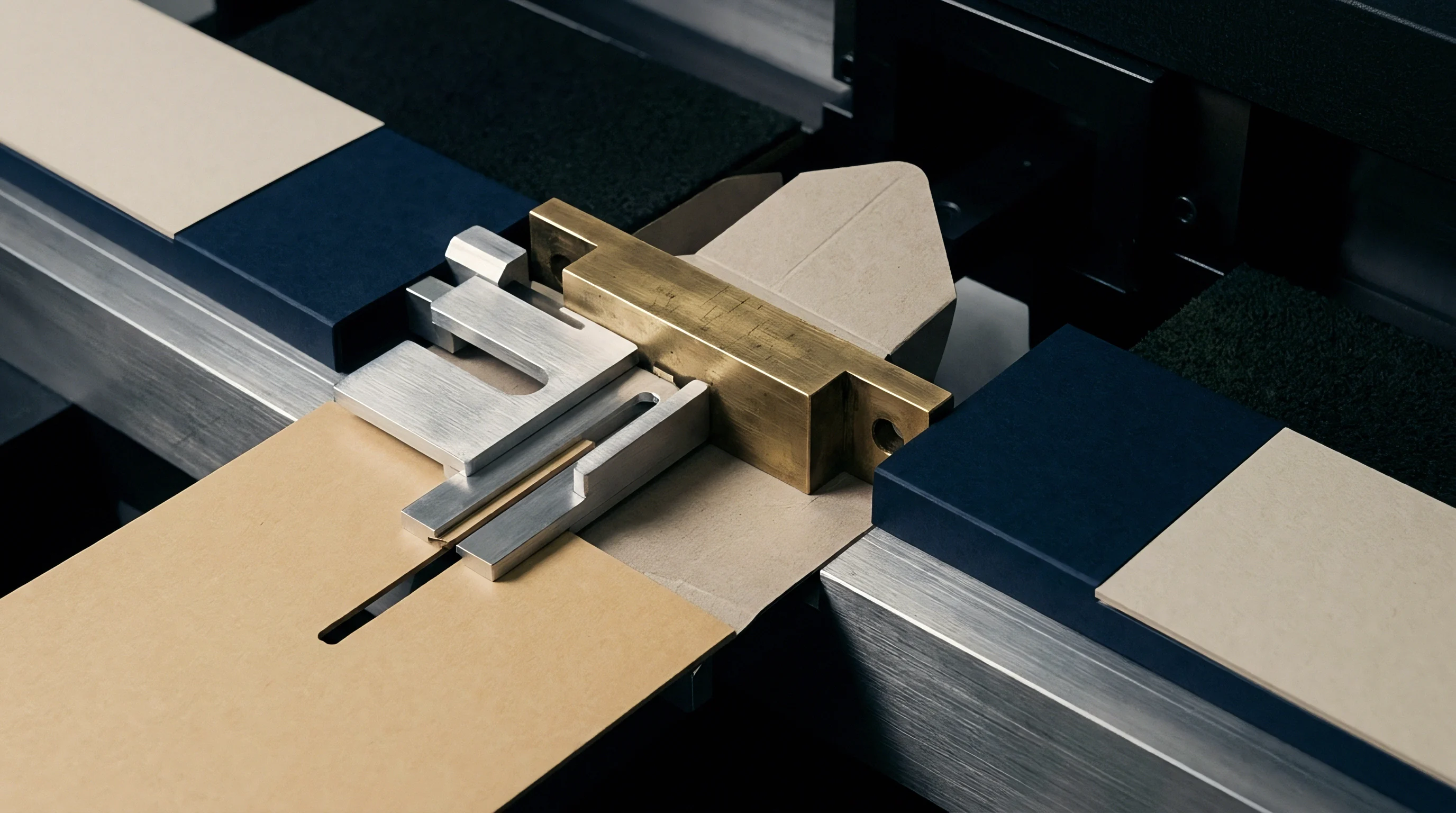
Combination foil and embossing passes require male counter dies ~ made from epoxy resin, fiberglass board, or milled brass ~ that mate with the female brass die. Alignment must be precise; even minor misalignment crushes paper fibers, shears the substrate, or distorts the embossed profile.
Because male counters sit on the lower bed, they operate much cooler than the top die ~ typically between 30°C and 45°C from conductive contact heat. Since the top brass die and bottom counter run at different temperatures, they expand at different rates. Scaling factors created for the top die cannot simply be copied to the male counter.
Counter artwork requires its own scaling calculation based on bottom bed temperature and the counter material’s expansion properties. Glass-reinforced epoxy counter plates, for instance, have a coefficient around 14.0 x 10^-6 per Kelvin. Matching a top brass die scaled for 135°C with a counter scaled for 35°C keeps register pin-aligned once the press reaches operating heat.
Tooling purchase orders should specify scaling conditions to clarify responsibility for misregistration:
- Thermal calibration baseline declaration specifies the ambient reference temperature, target operating temperature, and verified alloy expansion coefficient used for toolpath generation.
- Independent axis scaling record documents the individual percentage modifications applied to horizontal and vertical artwork vectors in CAD artwork files.
- Counter die registration clearance defines the engineered mechanical gap between male and female die profiles, accounting for thermal differential growth and substrate caliper.
- Dimensional verification audit certificate provides pre-shipment optical CMM measurement logs confirming engraved tool geometry at 20°C ambient baseline.
Orders that lack explicit thermal scaling notes effectively pass all financial liability for register errors onto the printer.

Inspection
Checking artwork scaling on press requires calibrated metrology instruments and systematic measurement. Relying on shop lighting and handheld loupes will not catch thermal drift before significant substrate is wasted. Quality control needs consistent press-side thermal checks and optical grid measurements throughout each shift.
Platen temperature audits should use calibrated infrared cameras or contact thermocouple probes. Infrared pyrometers must be set to match the emissivity of the brass surface, which varies from 0.05 on mirror-polished brass to 0.60 on warm, oxidized plates. Uncalibrated IR cameras can underread actual surface heat by up to 30°C, prompting operators to overheat platens and ruin scaling calculations.
Spring-loaded contact thermocouples offer better accuracy on reflective brass. Inspectors record readings across a 16-point grid over the chase area, looking for temperatures within +/- 2.5°C of target. Wider variations signal failing heater elements, damaged wiring, or uneven chase clamping pressure that flexes the die.
Platen Metrology and Thermal Imaging Audits
Monitoring temperature during production catches thermal shifts as press speeds rise from make-ready up to 5000 sheets per hour. Increased airflow shifts radiant heat loss, while friction from repeated platen impacts adds heat to lower bed assemblies over long runs.
An 8°C platen temperature creep over a four-hour run expands a 1000 millimetre brass die by another 0.154 millimetres, pushing outer artwork elements outside print-to-foil traps. Automated temperature controls must adjust zone heating based on real-time sensor readings to keep the die stable.
| Metrology Tool | Measured Variable | Measurement Precision | Calibration Standard | Action Threshold Limit |
|---|---|---|---|---|
| Contact Surface Thermocouple | Platen Surface Temp | +/- 0.5 C | NIST Traceable Reference | Greater than +/- 2.5 C Variance |
| Calibrated Thermal Imager | Chase Heat Uniformity | +/- 1.0 C | ASTM E1933 Standard | Greater than 5.0 C Edge Gradient |
| Optical CMM Grid System | Die Vector Geometry | +/- 0.001 MM | ISO 10360 Metrology | Greater than 0.020 MM Vector Drift |
| Contact Depth Gauge | Relief Cavity Depth | +/- 0.002 MM | DIN 863 Micrometer Spec | Greater than 0.050 MM Depth Error |
| Pressside Digital Microscope | Print Foil Trap Alignment | +/- 0.005 MM | Glass Reticle Standard | Greater than 0.100 MM Registration Error |
Optical Vernier Verification and Grid Tracking
Checking registration on press relies on test targets engraved into the waste margins of the die layout. Precision optical verniers, crosshairs, and star targets across all four quadrants let operators compare early stamped sheets against offset print targets to measure X and Y drift.
Optical verniers detect variances down to 0.025 millimetres. Offsets are checked at the drive side, operator side, gripper edge, and tail edge. Uniform drift across all corners points to incorrect prepress scaling, while uneven drift ~ like good alignment at the gripper but misregister at the tail ~ signals sheet skew, worn grippers, or uneven impression pressure.
Contact pyrometry using spring-loaded surface thermocouples delivers surface measurement accuracy within 0.5°C on polished brass chase dies.
High-resolution cameras mounted at press delivery scan passing sheets under strobe lighting. Image software tracks target coordinates against CAD specifications, flagging the operator or ejecting bad sheets if thermal drift pushes registration past tolerance.
Fluctuations in ambient relative humidity across pressrooms can invalidate calculated prepress artwork scaling factors during multi-day production runs.

Yield
Accurate artwork scaling directly affects scrap rates and job profitability in high-end packaging. Without proper compensation, operators compensate on press by running platens at improper temperatures or over-impressing sheets to stretch them into registration. These workarounds accelerate die damage, wear out presses, and generate heavy material scrap.
Make-ready waste consumes a big chunk of margin on short and medium runs. Standard waste allowances for complex packaging run between 2 and 4 percent of job volume, but uncompensated thermal expansion can push make-ready scrap past 10 percent as operators struggle to align static tooling with offset print marks.
Substrates represent the largest single cost item in packaging jobs, especially with premium SBS, metallized board, or soft-touch film laminates. Spoiled sheets from off-register stamping passes cannot easily be reclaimed, often triggering higher waste fees under European circular packaging regulations.
Tooling Amortization and Scrap Rate Mechanics
Ordering temperature-compensated brass dies adds a modest engineering surcharge upfront. Precision CNC milling, custom vector scaling, and CMM measurement certification increase tooling invoices by about 10 to 15 percent ~ adding roughly 300 Euros to a 2500 Euro large-format die.
That upfront fee pays for itself immediately on press. Eliminating thermal registration issues cuts setup time by up to 45 minutes per changeover. With platen press rates between 250 and 450 Euros per hour, the saved make-ready time recovers the extra tooling cost on the very first setup.
On a 100,000-unit run, the savings are substantial. Assuming 0.45 Euros per sheet and press costs of 350 Euros per hour, dropping scrap rates from 6 percent down to 1.5 percent saves over 2,000 Euros in stock alone, while preventing costly customer rejections.

Make Ready Spoilage and Commercial Break Even
Production sign-off sheets must record precise technical specifications before releasing CAD files for engraving. Formal sign-off records protect brand owners, prepress houses, and converters by establishing clear technical accountability.
Approved artwork releases should include:
- Target platen operating temperature specification establishes the exact press bed temperature mandated for the approved foil and substrate combination.
- Batch substrate moisture content declaration records baseline paperboard relative humidity measured under standardized ISO 187 testing conditions.
- Axis specific scaling factor verification confirms the exact percentage modifications applied to horizontal and vertical vector assets in CAD artwork files.
- Metrology calibration sign-off line records the certified optical measurement report confirming die dimensional accuracy at 20°C ambient baseline.
Clear guidelines for artwork scaling protect job margins and keep registration tight across every run.