Calibrating Crease Channel Width for Matte Laminated Folding Cartonboard
Matte laminated boxboard demands channel width expansion of twelve to eighteen percent over raw stock formulas to absorb film strain and prevent score rupture.
Axis
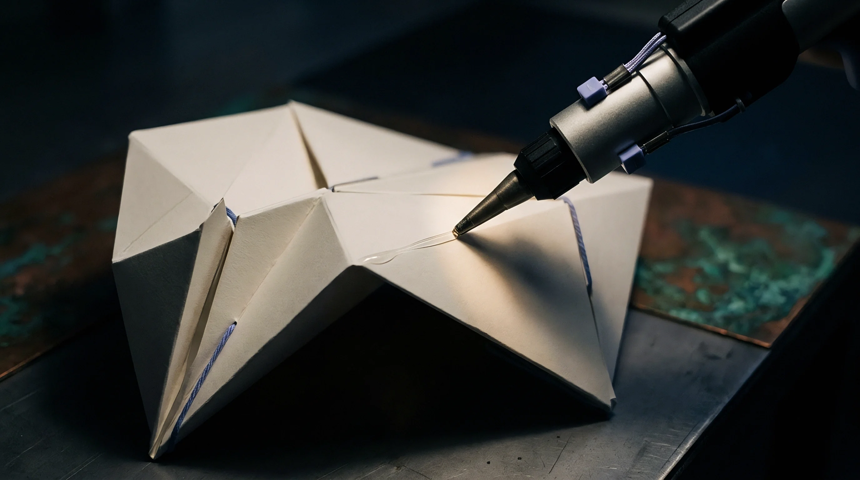
Bending a multi-ply cartonboard sheet puts the outer surface under high tension while compressing the inner plies beneath. In unlaminated folding boxboard (FBB) or solid bleached sulphate (SBS), uniform flexure places the neutral bending plane near the geometric center of the cross-section. Bonding a matte polymeric film ~ such as a twelve-micron biaxially oriented polypropylene (BOPP) or polyethylene terephthalate (PET) ~ to the top liner with polyurethane or acrylic adhesive pulls that neutral plane toward the outer laminated surface.
Because the synthetic film’s elastic modulus differs from the cellulosic fibers underneath, the film resists stretching as the die cutter drives into the score line. As the creasing rule pushes the board into the female counter matrix to form an internal fold bead, failing to recalibrate the channel for this shift concentrates hoop stress on the matte surface, causing micro-fractures along the crease.
Cellulosic fiber networks absorb strain through internal delamination ~ a shear breakdown between individual board plies that forms the flexible hinge needed to reduce folding torque. Adding a matte film alters how that energy dissipates. The micro-textured surfaces of matte films, whether created by mechanical embossing or silica matting agents, cut light reflection while acting as local stress risers.
With a complete adhesive bond, the top liner cannot slide freely under the film during die impact, concentrating strain over the rule radius rather than spreading it across a wider deformation zone. Sizing the matrix channel for uncoated board forces too much material into the groove, driving lateral compaction high enough that the film exceeds its yield strain and tears before internal delamination can relieve the stress.
Neutral Plane Displacements under Flexural Bending
Under angular folding, composite materials redistribute stress according to the stiffness of each layer. In a standard four-hundred-micron FBB sheet, the top liner accounts for roughly twenty-five percent of total caliper, while the middle mechanical pulp layers supply bulk and bending stiffness. Laminating a twelve-micron matte OPP film to the top liner introduces a high-modulus polymer skin that shifts the neutral axis six to ten percent outward.
As the outer film stretches across the bend radius during creasing and subsequent ninety-degree folding on automated gluers, the strain varε on the matte film follows the geometric relation:
varε = fracyρ
Wider female channels increase the bend radius ρ, directly reducing strain on the surface film. Retaining standard channel dimensions intended for unlaminated stock keeps the bend radius tight, driving strain past the six-to-eight percent yield limit typical of matte BOPP. The polymer then yields plastically, developing visible light-refracting micro-voids (crazing) or tearing to reveal the underlying fiber.
The bond strength between film and top liner determines where shear failure occurs. Solventless polyurethane adhesives applied at 1.2 to 1.8 grams per square meter yield bond strengths higher than the Z-directional tensile strength of the liner itself. As the rule descends, the film drags the top liner laterally into the channel.
Strong interfacial adhesion prevents local slip between polymer and cellulose, forcing the top liner into tensile elongation rather than letting it shear cleanly from the core plies. While reducing coat weight might promote delamination, it risks film peeling during carton handling; the proper correction is expanding the channel to fit the laminate’s displacement envelope.
Film Tensile Limits and Delamination Dynamics
Polymeric surface coatings change how paperboard behaves under die scoring. Matte PET films offer higher tensile strength and lower elongation at break than extruded matte polyethylene or biaxially oriented polypropylene. A twelve-micron matte PET film generally fractures at three to five percent strain, whereas matte BOPP tolerates six to ten percent before cracking.
Bio-based matte films like cellulose acetate or polylactic acid (PLA) exhibit even tighter limits, often splitting under three percent strain in cold press conditions. Ultimately, the chosen film substrate sets the boundary for allowable surface deformation.
Grain direction relative to the crease line also dictates surface strain. Creases parallel to the paperboard machine direction (MD) run between aligned fibers, encountering lower delamination resistance so the sheet collapses readily into the matrix channel. That rapid collapse creates a narrow, sharp internal bead that forces a tight bend radius onto the outer film.
Cross-machine direction (CD) creases encounter transverse fiber stiffness, forming wider, rounder beads that spread strain over a larger radius. Consequently, MD creases on matte laminated boxboard require wider channel settings than CD creases on the exact same board.
Substrate density and fiber structure govern how much the board compresses during scoring. Solid bleached sulphate consists entirely of dense chemical pulp, requiring higher creasing force to trigger internal shear. Folding boxboard features a bulky mechanical pulp core that compresses easily under vertical load.
On SBS, combining a dense paperboard surface with an unyielding matte film demands wider channel clearances to prevent surface shear. On FBB, although the soft mechanical core absorbs vertical displacement, the rigid film skin still requires extra lateral channel space to prevent top-ply splitting.
Using standard channel widths on matte laminated cartonboard leads to score line cracking, edge delamination, excessive springback that jams packaging equipment, and reduced box strength under stacking loads.
Shear
The polymer film choice dictates how laminated board responds during high-speed converting. Unlaminated boxboard relies on the elasticity of cellulosic fibers to absorb shear stress from die cutting and creasing rules. Adding a matte film converts that porous network into a constrained multi-layer composite.
Matte finishes rely on embedded inorganic micro-particles ~ such as synthetic silica or calcium carbonate ~ or co-extruded layers of incompatible polymers. While these particles scatter light, they also act as stress risers within the polymer matrix. Under shear in a creasing matrix, micro-tears form around particle boundaries much earlier than in a smooth gloss film of identical thickness.
Internal bonding force between plies is measured as Z-directional tensile strength under ISO 15754 or TAPPI T 541, typically ranging from 250 to 450 kilopascals in high-grade folding boxboard. When the creasing rule hits the board, vertical displacement forces the inner plies to shear laterally while the film remains under tension. If the matrix channel is too narrow, lateral shear stress exceeds top-liner Z-tensile strength before the core breaks down.
The top liner then separates from the middle ply while remaining stuck to the film, creating a raised, hollow ridge along the score (blistering or ridge lifting) that degrades appearance and hinge strength.
Matting Agents as Microscopic Stress Concentrators
Silica particles in synthetic coatings scatter light to yield a low-gloss finish without bonding chemically to the surrounding polypropylene or polyester matrix. On flatbed die cutters running around six thousand sheets per hour, stress accumulates rapidly over the rule tip, concentrating at the boundaries between the elastic polymer and rigid silica particles. This drops elongation at break by up to forty percent relative to an unfilled gloss film of the same resin, meaning a film that bends cleanly by hand during hand-sampling can easily split at press speed.
Friction further complicates score formation. Matte films exhibit higher static friction against steel matrix walls than gloss films, frequently exceeding 0.45 in dry ambient air. As the rule drives the laminated board into the channel, the matte surface drags across the matrix shoulders.
Instead of sliding smoothly into the groove to build a clean bead, the film grips the channel edges, stretching tightly across the center of the score. Widening or chamfering the matrix shoulders reduces this drag, allowing the film and liner to draw into the channel without over-stretching.

Interfacial Bond Strengths across Laminate Interfaces
Fold stability relies heavily on the bond between the polymer and the underlying chemical pulp liner. Corona treatment elevates polypropylene surface energy from thirty-one dynes per centimeter up to thirty-eight or forty-two, allowing water-based or solventless adhesives to wet out correctly. If corona treatment degrades prior to lamination, bond strength drops below fifteen Newtons per meter.
Low adhesion permits local film separation during scoring, which relieves strain and avoids cracking but leaves visible wrinkling along the crease line. High bond strength forces the film to take the full flexural strain, making accurate channel calibration critical.
Table 1 compares the mechanical and physical properties of unlaminated and matte laminated paperboards under standard scoring conditions, showing the drop in strain tolerance caused by matte surface treatments.
| Substrate & Finish Combination | Total Caliper (µm) | Film Base & Thickness | Matte Additive Type | Film Elongation Limit (%) | Z-Tensile Strength (kPa) | Crease Shear Threshold (N/m) |
|---|---|---|---|---|---|---|
| Bleached Board (SBS) Unlaminated | 350 | None | None | 12.5 | 410 | 185 |
| Bleached Board (SBS) + Gloss OPP | 362 | 12 µm OPP | None | 9.0 | 405 | 210 |
| Bleached Board (SBS) + Matte OPP | 362 | 12 µm OPP | Silica (3.5 µm) | 5.5 | 395 | 245 |
| Bleached Board (SBS) + Matte PET | 362 | 12 µm PET | Co-extruded resin | 3.8 | 400 | 270 |
| Folding Boxboard (FBB) Unlaminated | 450 | None | None | 14.0 | 290 | 140 |
| Folding Boxboard (FBB) + Matte OPP | 462 | 12 µm OPP | Silica (3.5 µm) | 6.0 | 280 | 190 |
| Recycled Board (CRB) + Matte OPP | 450 | 12 µm OPP | Silica (3.5 µm) | 4.2 | 220 | 225 |
The failure modes observed during matte laminated cartonboard converting stem from specific structural breakdowns across the polymer, adhesive, and fiber layers:
- Film micro-fracturing begins along silica concentration lines when circumferential tension exceeds polymer yield limits.
- Top liner delamination occurs when strong adhesive bonding transfers film tension into the upper chemical pulp layer.
- Internal ply shear collapse happens when narrow channels restrict lateral movement, crushing the middle mechanical plies.
- Adhesive seam separation occurs when low-energy, corona-decayed film detaches under flexural rebound.
- Bead springback deviation stems from incomplete core displacement, leaving high panel torque during automatic carton erecting.
When micro-cracking occurs on matte laminated jobs, film specifications often meet nominal tensile targets, prompting operators to back off impression pressure or raise ambient humidity rather than fixing channel geometry.
At twenty-three degrees Celsius and fifty percent relative humidity, matte biaxially oriented polypropylene exhibits an elongation limit of sixty-five percent before localized whitening occurs.


Calibration
Matrix formulas developed for raw boxboard fail on surface-laminated materials. In traditional converting, channel width W relies on the standard calculation:
W = (1.5 × tb) + tr
where tb represents unlaminated board caliper and tr is creasing rule thickness. For a four-hundred-micron (0.40 mm) raw sheet and a two-point (0.71 mm) rule, this gives a channel width of W = (1.5 × 0.40) + 0.71 = 1.31 mm. That calculation works for unlaminated FBB or SBS, but using the same width on matte laminated stock leads to top-liner splitting and surface crazing along the score edges.
Laminating a matte film increases total caliper and changes how the board deforms. Calibrating for matte laminated board requires replacing the 1.5 multiplier with an expanded factor between 1.7 and 1.9, applied to total composite caliper tc (combining board, adhesive, and film). The revised equation becomes:
Wm = (Km × tc) + tr
where Km is the matte lamination factor (1.75 for standard matte OPP; 1.85 for stiffer matte PET or bio-films) and tc is total composite caliper. Recalculating for four-hundred-micron board with twelve-micron matte OPP (tc = 0.412 mm) at Km = 1.75 yields Wm = (1.75 × 0.412) + 0.71 = 1.43 mm. This widens the channel by 0.12 mm ~ about nine percent over the unlaminated baseline ~ opening the bend radius at the root of the fold to reduce peak surface strain.
Where Does Crease Depth Control Fail under Speed?
Dynamic impact on high-speed platen presses influences penetration depth, while press deflection, thermal expansion, and matrix wear cause channel depth d to drift over long runs. Unlaminated board setups typically set matrix depth equal to board caliper (d = tc). Matte laminated boards demand tighter control: an overly shallow channel crushes core plies and pinches film against rule edges, whereas excessive depth prevents proper internal shearing, resulting in a stiff core and high flap springback.
Channel depth for matte laminated board should target d = 0.90 × tc to 0.95 × tc on dense SBS, and d = 1.0 × tc on bulky FBB. On dense substrates, a slightly shallower channel uses the added stiffness of the film to encourage internal delamination before surface tension hits the film’s yield limit. This shallower channel must always be paired with the expanded width Wm; together, they distribute bending strain across a broader arc, protecting the silica-filled film surface while ensuring the fiber core shears cleanly.

Mathematical Adjustments for Polymeric Film Additions
Rule tip radius Rr also governs stress concentration along the fold. Standard rules use a tip radius equal to half the rule thickness (Rr = 0.5 × tr), yielding 0.355 mm on a two-point (0.71 mm) rule. On matte laminated stock, this narrow profile pinches the film along two sharp shear lines.
Using rules with a larger tip radius (Rr = 0.75 × tr to 1.0 × tr) or a contoured crown spreads the impression force. A 0.71 mm rule with a 0.50 mm tip radius softens the profile, guiding the film into the expanded channel without initiating micro-cracks. Pairing a larger tip radius with the expanded width Wm cuts peak tensile strain by up to twenty-eight percent, allowing brittle PET and bio-based films to fold ninety degrees intact.
Table 2 provides channel width calibrations across standard board calipers, comparing unlaminated settings with corrected values for matte laminated board.
| Board Type & Nominal Caliper | Total Composite Caliper tc (mm) | Creasing Rule Thickness tr | Uncoated Channel Width W (mm) | Matte OPP Multiplier Km | Calibrated Matte Channel Width Wm (mm) | Recommended Matrix Depth d (mm) |
|---|---|---|---|---|---|---|
| FBB 300 µm (0.30 mm) | 0.312 | 2 Pt (0.71 mm) | 1.16 | 1.75 | 1.26 | 0.30 |
| FBB 400 µm (0.40 mm) | 0.412 | 2 Pt (0.71 mm) | 1.31 | 1.75 | 1.43 | 0.40 |
| FBB 500 µm (0.50 mm) | 0.512 | 3 Pt (1.05 mm) | 1.80 | 1.75 | 1.95 | 0.50 |
| SBS 350 µm (0.35 mm) | 0.362 | 2 Pt (0.71 mm) | 1.24 | 1.80 | 1.36 | 0.33 |
| SBS 450 µm (0.45 mm) | 0.462 | 3 Pt (1.05 mm) | 1.73 | 1.80 | 1.88 | 0.42 |
| CRB 400 µm (0.40 mm) | 0.415 | 2 Pt (0.71 mm) | 1.31 | 1.85 | 1.48 | 0.40 |
| CRB 500 µm (0.50 mm) | 0.515 | 3 Pt (1.05 mm) | 1.80 | 1.85 | 2.00 | 0.50 |
Setting up matrix calibration on production dies requires a systematic approach during make-ready:
- Measure total composite thickness with a digital micrometer under ISO 534 conditioning.
- Determine base rule thickness and matrix depth according to substrate density and ply structure.
- Apply the matte lamination correction factor to widen channel width by fourteen to eighteen percent.
- Adjust press impression pressure to compress the board by roughly sixty percent without indenting the film wall.
- Check bead geometry and crease stiffness on an automated bending tester at ninety degrees.
Sizing matrix channel width strictly from board caliper without accounting for the film’s tensile modulus frequently leads to score failure on automatic packaging lines.
Standard ISO 5628 compliance requires flexural stiffness measurements to reflect actual panel resistance without influence from score springback variance.
Tooling
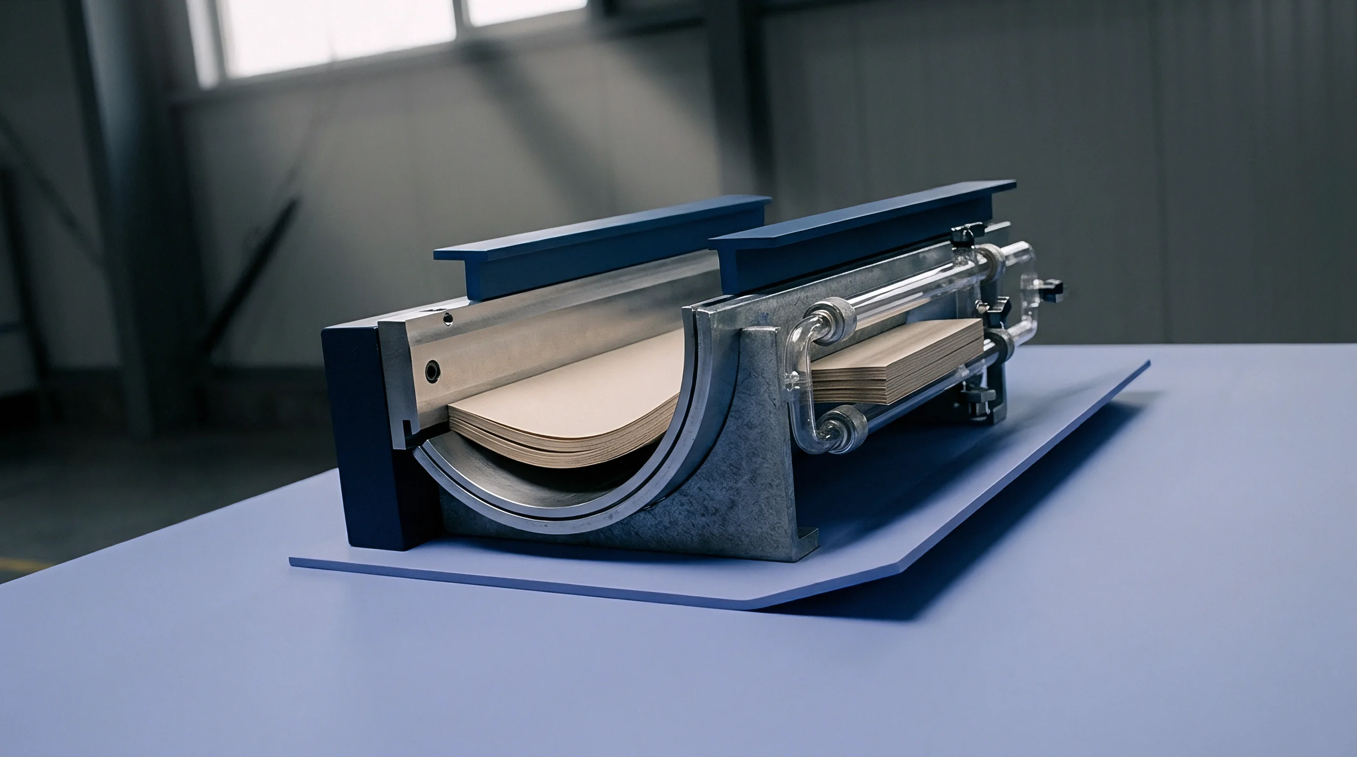
Flatbed die cutters produce intense impact forces, driving creasing rules into paperboard at speeds reaching eleven thousand sheets per hour. Standard rules feature straight side walls and a semi-circular crown, a shape that creates sharp lateral displacement along channel shoulders when applied to matte laminated board. Modified rule profiles ~ like relief-bevel or double-crease designs ~ redistribute impact forces.
A relief-bevel rule lowers sidewall friction, keeping the matte film from snagging on the shoulders at full penetration depth.
Matrix durability determines whether channel tolerances hold over extended production runs. Shops generally choose between press-applied synthetic matrix strips (phenolic resin, vulcanized fiber, or pressboard on steel channels) and CNC-milled steel counter plates. Synthetic strips offer lower initial cost and quick make-ready setup, but their side walls compress under repeated impacts.
Over fifty thousand impressions, lateral compaction can reduce effective channel width by as much as eight percent. On tight-tolerance matte laminated work, this wear gradually closes down the target width Wm, triggering film splits mid-run. CNC-milled steel plates retain exact channel geometry across millions of cycles, making them mandatory for high-volume jobs.
Rule Tip Profiles and Penetration Kinematics
Adjusting creasing rule tip radii modifies how force transfers during penetration. Standard two-point rules carry a 0.35 mm radius, whereas specifying a 0.50 mm or 0.60 mm radius on matte laminated FBB expands the contact footprint. That broader contact area compresses a larger section of top liner simultaneously, triggering internal ply shear before film elongation exceeds its yield point.
Hard-chrome plated rules further reduce drag, allowing the matte surface to slide across the crown without scuffing.
Matrix shoulder profile is just as critical. Standard matrix channels feature sharp ninety-degree corners that drag heavily against the film during scoring. Channels engineered for film laminates incorporate chamfered or radiused shoulders ~ typically a forty-five-degree chamfer or a 0.20 mm radius.
These rounded entries let the top liner transition into the channel without pinching, reducing tensile strain on the surface film by fifteen to twenty percent.

Counter Die Selection and Phenolic Channel Durability
Phenolic matrix materials resist pressroom humidity and temperature shifts, providing essential wall rigidity when running matte film. Lower-grade plastic strips flex under load, narrowing effective channel width and producing inconsistent crease depths across the form. Phenolic channels maintain structural integrity under high tonnage, while for runs exceeding one hundred thousand sheets, CNC-milled steel plates eliminate channel wear altogether so Wm remains constant from the first impression to the last.
Matrix tape movement during press operation introduces another point of failure. Machine vibration can creep stick-on strips by fractions of a millimeter. A shift of only 0.10 mm creates an off-center crease, over-stretching the film on one shoulder while reducing depth on the other and causing splits along the tight edge.
Preventing strip movement demands high-shear acrylic adhesive tapes along with optical alignment checks during setup.
Choosing tooling for matte laminated board requires balancing material durability, shoulder profiles, and rule edge profiles across the entire die:
- Phenolic matrix selection provides rigid channel walls that resist lateral flexing under impression loads.
- Chamfered channel profiles remove sharp shoulder edges, allowing the matte film to draw smoothly into the groove.
- Increased rule tip radii spread vertical force over a wider area, protecting low-elongation films.
- Platen parallelism checks ensure even impression depth, preventing local pinching along die balance blocks.
Using standard square-edged matrix strips to cut initial tooling costs frequently leads to film splitting and rejected carton lots.
Purchasing agreements for custom steel counter plates must specify channel width tolerances within plus or minus ten microns across the entire die layout.

Inspection
Manual hand-folding is an unreliable test for score lines on matte laminated board. Because silica-filled films are strain-rate sensitive, a crease that bends smoothly by hand can split when processed on an automated folder-gluer running at four hundred meters per minute. Reliable quality verification requires testing under controlled speed, angle, and atmospheric conditions before releasing a job to production.
Evaluating crease quality combines microtome cross-sectioning, bending torque measurement (ISO 2493-1 / DIN 53121), and magnified inspection. Sectioning perpendicular to the score line under 20x magnification reveals internal ply behavior: a properly calibrated crease displays broad, symmetrical ply separation ~ the internal fold bead ~ without top-liner fracturing or film splits. Intact middle plies alongside a pinched outer film indicate the matrix channel is too narrow and requires expansion.

Cross Sectional Microscopy and Bead Symmetry
Microscopic evaluation of sectioned samples confirms bead symmetry and core delamination. A centered, symmetrical bead verifies accurate matrix alignment and balanced bed pressure, whereas an asymmetrical bead points to off-center registration or uneven press leveling. Cross-sections also expose adhesive bond failure; if the glue line breaks from the top liner during creasing, the film bubbles upon folding.
Visualizing the structure isolates whether film failure originates from polymer strain limits or substrate breakdown, directing operators to the correct remedy.
Folding torque testing measures the resistance encountered when folding creased flaps. Automated devices like Marbach Crease Testers or Lorilleux instruments record peak torque as the sample folds through ninety degrees at controlled speed. The crease ratio Cr compares creased bending resistance Bc against uncreased panel resistance Bu:
Cr = fracBcBu × 100
While unlaminated boxboard targets a crease ratio of forty to fifty-five percent, matte laminated boards require thirty-five to forty-five percent. Achieving this lower range demands widening the matrix channel sufficiently to maximize internal ply breakdown, which lowers folding resistance and prevents springback torque from bursting glued joints on packaging lines.
Bending Torque Measurement and Score Stiffness Ratios
Excessive flap stiffness during carton setup causes vacuum cup misfeeds, joint failure, and line stoppage. Sample conditioning per ISO 187 standards (twenty-three degrees Celsius, fifty percent relative humidity) establishes reliable torque baselines. Supplementary testing under low humidity (such as twenty percent RH) catches seasonal fiber embrittlement early, allowing press operators to adjust matrix geometry for dry winter conditions.
Recyclability testing under EPRC or PTS-RH 021/97 protocols evaluates how laminated boards re-pulp in paper mill systems. Laminated cartons retain recyclability provided the polymer skin detaches cleanly and can be screened out during hydrapulping. Although high-strength adhesives complicate separation, correct channel sizing prevents the film from fracturing during scoring, allowing it to peel off in large sheets during pulping rather than breaking into fine plastic fragments.
A standard QA clearance routine for matte laminated jobs requires documenting several key parameters before releasing the press for production:
- Substrate certificate of analysis showing board caliper, moisture content, Z-tensile strength, and grain direction.
- Adhesive coat weight logs verifying dry coverage between 1.2 and 1.8 grams per square meter across the web.
- Crease resistance test results confirming fold torque ratios stay below forty-five percent at ninety degrees.
- Environmental test records verifying cracking resistance after twenty-four hours at fifteen percent relative humidity.
Monitoring matrix stability throughout long runs prevents unexpected cracking as press temperatures and vibrations shift.
Moisture loss during winter storage increases fiber brittleness and converts minor score stress into visible panel cracking.

Yield
Carton converting margins rely heavily on controlling waste and minimizing press downtime. Running matte laminated board with matrix dimensions intended for unlaminated stock introduces severe operational risk: reduced press speeds, high make-ready waste, and customer returns rapidly undermine profitability. Matte films add fifteen to twenty-five percent to raw material expenditure, and plastic-laminated waste sheets cannot be resold as clean paperboard scrap.
Setup spoilage rises when operators attempt trial-and-error adjustments to stop score cracking. Tweaking impression pressure on an undersized matrix channel wastes hundreds of sheets without fixing micro-cracks. Pre-calculating matrix width Wm using total composite caliper tc and film limits removes this guesswork.
Reducing make-ready waste from five hundred sheets down to under eighty saves material and recovers up to forty minutes of press time per changeover.
Make-Ready Spoilage and Machine Speed Penalties
When matrix channels are too tight, operators frequently back off impression pressure to prevent film cracking. While this avoids immediate surface splits, it produces shallow, poorly formed creases with high springback. On automated packaging lines, stiff box flaps cause feeder jams that cut cartoning speeds in half.
The resulting downtime claims and rejected shipments far exceed the cost of proper matrix engineering.
Restricting press speed to protect fragile score lines masks substantial financial loss. Operating a die cutter rated at nine thousand sheets per hour at six thousand to avoid cracking represents a thirty-three percent loss in output. With hourly press costs between two hundred and three hundred and fifty dollars, that speed reduction inflates unit conversion costs and erodes operating margins.
Counter Plate Tooling Economics and Modular Systems
Selecting between synthetic matrix channels and milled steel counter plates comes down to job volume. Phenolic matrix strips cost thirty to fifty dollars per form and take roughly thirty minutes to apply during make-ready. Milled steel plates require eight hundred to fifteen hundred dollars in upfront tooling and several days of lead time.
For runs under twenty thousand sheets, phenolic matrix strips sized to width Wm deliver the right balance of low tooling cost and adequate service life.
For orders exceeding fifty thousand sheets, steel counter plates become more economical. CNC-milled channels preserve exact dimensions over long runs, preventing channel degradation and mid-run press stoppages. Modular steel counter systems also allow converters to replace individual channel inserts instead of buying entire new plates for repeat orders, keeping long-term tooling expenses under control.
Table 3 models the production costs of a 100,000-carton run on matte laminated FBB, comparing an uncalibrated setup against calibrated synthetic matrix and milled steel counter plates.
| Cost & Performance Metric | Uncalibrated Setup (Standard Formula) | Calibrated Synthetic Matrix Setup | Precision Milled Steel Counter Setup |
|---|---|---|---|
| Initial Tooling Investment ($) | 45.00 | 55.00 | 1,200.00 |
| Make-Ready Waste (Sheets) | 650 | 120 | 40 |
| Make-Ready Waste Cost ($) | 585.00 | 108.00 | 36.00 |
| Operating Press Speed (Sheets/Hour) | 5,500 | 7,800 | 9,000 |
| Total Press Running Time (Hours) | 18.18 | 12.82 | 11.11 |
| Hourly Press Operating Cost ($) | 4,545.00 | 3,205.00 | 2,777.50 |
| In-Process Cracking Spoilage (%) | 4.2% | 0.3% | 0.05% |
| Spoilage Material Cost ($) | 3,780.00 | 270.00 | 45.00 |
| Extended Producer Responsibility Fee ($) | 420.00 | 420.00 | 420.00 |
| Total Landed Production Cost ($) | 9,375.00 | 4,058.00 | 4,478.50 |
The financial model demonstrates how uncalibrated matrix setups penalize production through extended press hours, high setup waste, and material spoilage. Calibrating synthetic matrix channels alone reduces conversion cost by over fifty percent on a 100,000-sheet run. Upgrading to milled steel counter plates permits maximum press speed and virtually eliminates spoilage, recovering the higher initial tooling expense on jobs above eighty-five thousand sheets.
Extended Producer Responsibility (EPR) regulations increasingly penalize non-recyclable composite packaging, imposing eco-levies up to two hundred and fifty Euros per metric ton on plastic-laminated cartonboard unless certified for re-pulping. Precise channel calibration allows converters to run thinner, recyclable twelve-micron film without score cracking, letting brand owners maintain a matte finish while qualifying for lower EPR fee tiers. Proper matrix engineering reconciles visual appearance, runnability, and regulatory compliance.