Creasing Channel Selection for Laminated Folding Boxboard Conversion
Select creasing channels for laminated folding boxboard using wider channel factors to protect surface polymer films from tensile rupture during folding.

Rule
Steel tools penetrating laminated folding boxboard set up severe multi-axial stress fields inside the fibrous plies. The top liner of folding boxboard carries tensile forces during indentation, while the mechanical pulp core undergoes localized shearing and compression. Adding a thermoplastic film, such as oriented polypropylene or polyethylene terephthalate, bonded via polyurethane adhesive changes how the outer fiber layer responds to mechanical scoring.
The polymer layer acts as a continuous tensile membrane over the paperboard surface. Without modified scoring dimensions, high localized elongation along the crease line exceeds the ultimate tensile strain of the film, inducing surface blistering, film split, or catastrophic top-liner tearing.

Composite Board Stress during Mechanical Indentation
Folding boxboard relies on a multi-ply structure containing bleached chemical pulp outer skins and a dense mechanical pulp center. During crease rule penetration, the bottom liner forces its way into the female matrix groove, establishing a double-shear plane through the sheet thickness. Internal delamination between the middle mechanical pulp layers allows the board to form a clean score bead without cracking the outer surfaces.
Shear stresses peak rapidly. When the board carries a polymer film, this internal shearing process must occur under higher vertical displacement forces. The surface film resists localized elongation, transmitting horizontal tension across the entire contact zone of the creasing rule tip.
Plastic lamination films prevent top liner micro-fractures from expanding into surface splits during board displacement.
Unlaminated boxboard dissipates tensile energy through micro-cracking of chemical pulp fibers along the outer score bend. Plastic film restricts this micro-fracturing mechanism, forcing tensile energy to concentrate along the narrow shoulder of the female channel edge. If the crease channel width matches unlaminated board standards, the steep strain gradient at the channel shoulder shears the adhesive layer.
The film yields. Tensile stress concentration causes the polymer film to detach from the top liner, forming an unbonded channel along the score line that appears as a white streak or visible bubble upon folding.
Polymer Film Tensile Behavior under Creasing Impact
Surface lamination layers alter how the top liner deforms under load. Oriented polypropylene film features an elongation at break between one hundred and one hundred sixty percent under slow uniaxial tension, yet under impact speed conditions of three thousand to six thousand sheets per hour on a platen die-cutter, dynamic strain hardening reduces film ductility sharply. The effective elongation before structural failure falls below eighteen percent under high strain rate press speeds.
Polyethylene terephthalate film exhibits even higher tensile modulus and lower peak elongation, increasing the resistance of the outer sheet face against entering the channel recess.
Adhesive bonding choice dictates whether stress distribution remains localized or disperses across the score zone. Solventless two-component polyurethane adhesives yield dry coat weights between one point two and two point zero grams per square meter. A low coat weight or insufficient adhesive curing time allows film delamination under moderate score displacement.
Conversely, an over-cured or extremely rigid adhesive transfers maximum strain directly into the outer chemical pulp fibers, inducing fiber rupture directly beneath the film coating. Plies shear internally.
- Film blister detachment occurs when localized shear stress exceeds the bond strength of the polyurethane adhesive along the crease shoulder.
- Middle ply structural shear develops when excessive rule penetration crushes the mechanical pulp core completely, destroying the structural hinge.
- Back liner tensile rupture appears along the female channel edges when channel width falls below critical clearance limits for heavy caliper boards.
- Crease bead asymmetry results from improper rule centering or uneven channel wear across high-volume production runs.
Tooling suppliers often claim that standard scoring matrices handle film-laminated cartonboard without channel adjustments if press operators reduce overall impression pressure. That operational excuse overlooks the physical mechanics of polymer film elongation under dynamic platen impact.

Calculus
Dimensioning crease channels for film-laminated folding boxboard involves balancing elastic recovery with plastic deformation. Calculations for unlaminated boxboard utilize standard multiplier factors applied to board caliper to establish channel width and depth. Laminated boxboard requires expanded channel width parameters to accommodate film thickness, adhesive layer height, and the modified neutral axis position of the composite sheet.
Selecting channel depth demands equal precision, as shallow grooves fail to form an adequate score bead, while deep grooves cause excessive core crushing and internal shear fracture.
Mathematical Formulae for Matrix Width Determination
Selecting the correct channel opening requires exact accounting for paperboard caliper and tool thickness. Standard industry formulae calculate female channel width by multiplying total board caliper by a factor between one point four and one point six, then adding the creasing rule thickness. For plastic-laminated folding boxboard, this factor increases to a range of one point seven to one point nine to lower the shear angle at the matrix shoulder.
The composite caliper includes the base paperboard thickness, film thickness, and dry adhesive weight converted to equivalent caliper.
| Board Caliper (mm) | Film Type & Caliper (µm) | Rule Thickness (pt / mm) | Matrix Width Factor | Calculated Channel Width (mm) | Calculated Channel Depth (mm) |
|---|---|---|---|---|---|
| 0.350 | 12 µm Matt BOPP | 2 pt / 0.71 mm | 1.70 | 1.31 | 0.35 |
| 0.400 | 15 µm Gloss BOPP | 2 pt / 0.71 mm | 1.75 | 1.41 | 0.40 |
| 0.450 | 12 µm PET Film | 2 pt / 0.71 mm | 1.80 | 1.52 | 0.45 |
| 0.500 | 20 µm Soft-Touch BOPP | 3 pt / 1.05 mm | 1.85 | 1.98 | 0.50 |
| 0.600 | 24 µm Metalized PET | 3 pt / 1.05 mm | 1.90 | 2.19 | 0.60 |
| Calculated values utilize standard creasing rule heights of 23.80 mm on a standard 7.00 mm platen cutting plate thickness base under ISO 187 standard conditioning. | |||||
Channel depth calculations for laminated boxboard generally set female groove depth equal to base paperboard caliper. Heavy laminated grades exceeding five hundred micrometers benefit from adding zero point zero5 millimeters to matrix depth to prevent extreme mechanical core compression. Insufficient depth compresses the mechanical pulp core into a solid block, preventing internal delamination and raising folding resistance to levels that cause box automatic erecting machinery to misfeed.

Grain Orientation Adjustment Ratios for Laminated Stocks
Fiber direction relative to the score line fundamentally changes how plies delaminate. Parallel scores running along the machine direction bend across fibers aligned vertically, requiring less bending force but exhibiting higher susceptibility to outer liner cracking. Perpendicular scores running across the machine direction flex stiff wood fibers, requiring higher penetration depth to force permanent deformation.
Tension splits outer fibers.
A channel width factor of 1.7 times board caliper plus rule thickness prevents film strain exceeding twelve percent during cross-grain scoring.
Machine-direction creasing channel widths use a factor of one point seven times board caliper plus rule thickness. Cross-machine direction creasing requires a factor of one point eight5 to one point nine0 times caliper plus rule thickness. This expansion widens the shoulder radius over which the polymer film stretches, spreading tensile strain across a larger surface area and keeping film elongation within elastic deformation limits.
Adjust channel widths wider when board moisture content falls below six point five percent to prevent brittle surface fractures during high-speed converting.


Matrix
Counter-die materials provide the female recess that shapes the score bead. Material choices range from pressboard channels mounted on locator strips to synthetic phenolic laminates and precision-milled steel plates. Material stiffness and shoulder durability govern channel geometry stability over extended press runs.
Soft matrix materials compress under continuous impression pressure, widening the effective channel width and reducing score bead height over long production passes.

Which Matrix Depth Prevents Film Shear on Heavy Board?
Selecting female counter grooves for boards exceeding three hundred micrometers demands precise depth clearance. Channel depth matching board caliper exactly avoids shearing the middle mechanical pulp layer while allowing the film layer to sink into the groove without excessive stretch. For laminated grades above five hundred micrometers, increasing matrix depth by five hundredths of a millimeter creates room for the film layer without crushing the inner fibers.
Matrix walls deflect.
Phenolic resin matrix strips provide high structural stability for medium-to-long packaging runs. Phenolic base channels exhibit minimal compressive creep under platen loads exceeding two hundred metric tons. Smooth, chamfered shoulders on phenolic channels reduce friction as the laminated sheet enters the groove, lowering edge tension on the polymer film.
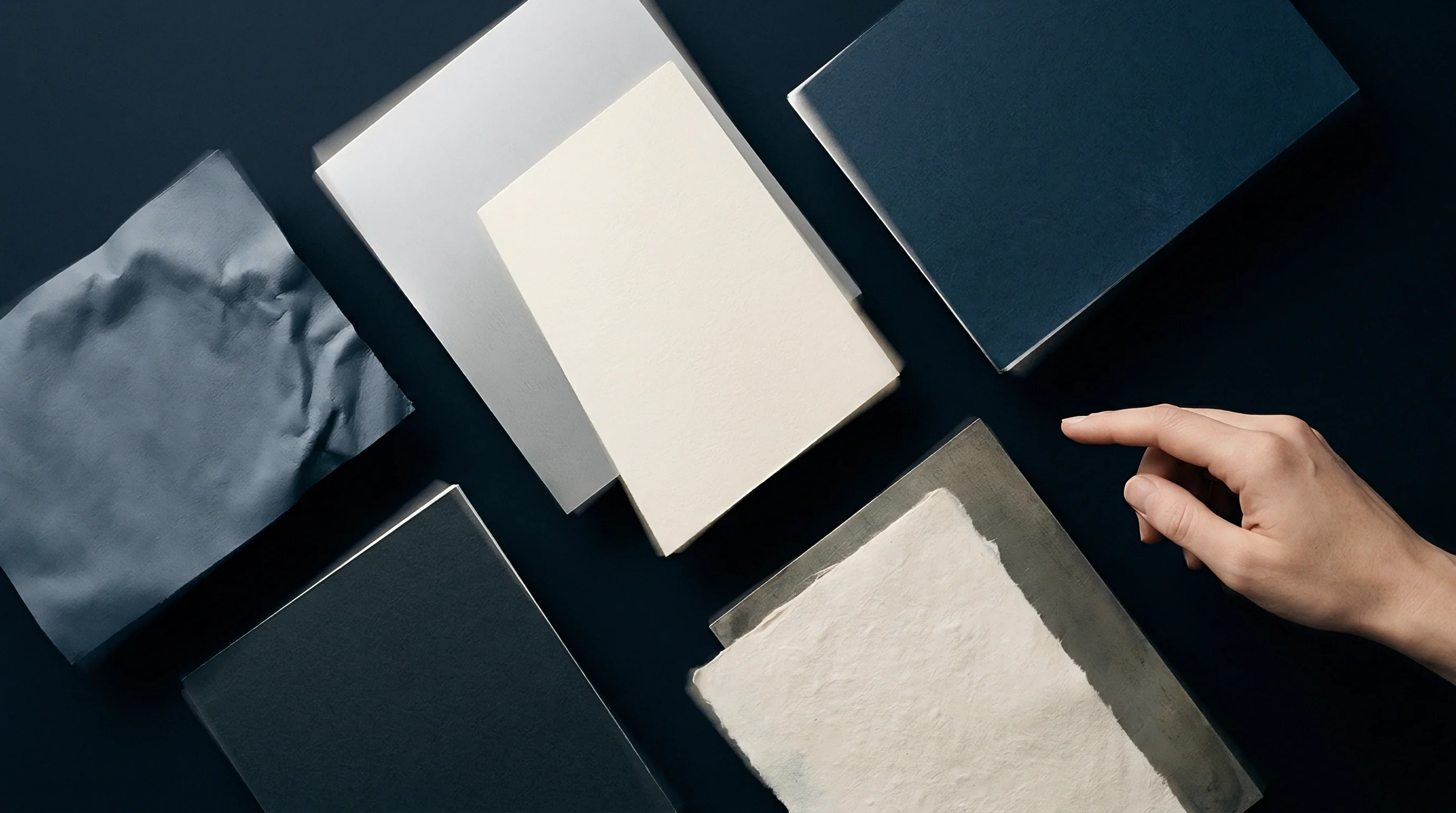
Substrate Compression Dynamics across Phenolic and PVC Counter Dies
Female scoring channels undergo significant compressive cycles during die-cutting runs. Standard polyvinyl chloride counter matrix strips offer rapid make-ready installation but exhibit plastic deformation after fifty thousand impressions. As matrix walls deform outward, the original groove width expands by up to ten percent.
Expanded channel width reduces score bead definition, causing sloppy fold registration and variable opening forces on carton filling lines.
Milled steel counter plates provide fixed channel geometry across million-sheet production contracts. Steel plates eliminate matrix shoulder breakdown completely, ensuring identical score profile geometry from the first sheet to the end of the batch. Milling steel requires precise CAD depth programming, accounting for adhesive thickness and film elongation parameters before tool manufacture.
- Measure initial caliper across five points on the laminated board sample using a digital micrometer under dead-weight force conditions.
- Select creasing rule point size and height based on die-cutting plate clearance specifications.
- Calculate required matrix channel width using grain direction adjustment factors for laminated stock.
- Mount chamfered counter die matrix strips onto the cutting plate using high-tack locator keys.
- Execute an initial hand-pulled impression pass to verify registration and bead symmetry across the layout.
- Measure creased bead height and width using an optical toolmaker microscope to verify drawing compliance.
The unresolved engineering issue remains whether micro-grooved metallic counter surfaces can eliminate polyurethane adhesive shear on ultra-thin gloss films without requiring wider channel openings that compromise fold sharpness.

Fracture
Structural failure along score lines compromises package integrity during automated high-speed carton erecting. Film-laminated boxboard failure modes differ significantly from unlaminated paperboard degradation. The bond interface between polymer film, adhesive coat, and paperboard top liner introduces a distinct shear plane.
Failure can occur within the fiber structure, within the polymer film, or across the adhesive boundary.

Delamination Mechanics at the Polyurethane Adhesive Layer
Interfacial bonding between polymer films and top paperboard liners resists high peel forces. Polyurethane adhesives bond via chemical cross-linking with surface fibers and physical anchor locks into paperboard pores. Creasing imposes high shear and peel forces simultaneously at the crease shoulder.
If adhesive surface energy drops below thirty-eight dynes per centimeter, delamination occurs instantly upon tool impact. Adhesives hold firm.
| Failure Mode | Physical Appearance | Primary Mechanical Cause | Standard Test Method | Corrective Action |
|---|---|---|---|---|
| Film Delamination | White blisters along score shoulder | Excessive shear at adhesive interface | FINAT FTM 2 Tape Peel Test | Widen channel width factor to 1.85 |
| Top Liner Splitting | Visible fiber tear under film coating | Tensile strain exceeding fiber limit | ISO 2758 Burst Testing | Reduce creasing rule height by 0.1 mm |
| Score Bead Rupture | Complete linear tear along crease trough | Excessive rule penetration depth | ISO 1974 Tear Resistance | Decrease channel depth or soft matrix |
| Film Micro-Crazing | Hazy white line along bend peak | Polymer elongation limit exceeded | ASTM D882 Tensile Properties | Increase matrix shoulder chamfer angle |
| Unstable Springback | Carton side panels bulge outward | Insufficient internal ply shearing | ISO 5628 Bending Stiffness | Increase rule penetration profile |
Top liner splitting underneath an intact film layer indicates excessive tensile concentration combined with strong adhesive bonding. The outer chemical pulp fibers fail under tension, but the polymer film remains intact. This hidden structural failure reduces score line bending resistance initially, but leads to severe corner bulge and edge crack propagation after repeat opening cycles.

Bending Moment Decay and Score Bead Springback Testing
Erecting forces for folded cartons depend directly on how well the creased hinge relaxes after scoring. Bending moment tests evaluate the force required to bend a scored sample to a ninety-degree angle at fixed angular velocity. Unlaminated boxboard demonstrates immediate bending force reduction due to core fiber delamination.
Film lamination introduces elastic memory, as the stretched polymer film continuously attempts to snap back to its planar shape.
Compliance with ISO 5628 stiffness protocols establishes baseline bending force thresholds for high-speed folding machine registration.
Springback forces cause automated packaging machine jams if creasing channels fail to induce adequate permanent set in the score bead. Higher springback forces require folding equipment glue belts to apply greater pressure, slowing overall line speed. Springback forces decline.
Proper selection of matrix channel width reduces springback energy by ninety-degree fold angle relaxation rates above sixty percent.
Score bead height drops. Selecting an incorrect creasing channel width for film-laminated folding boxboard leads to widespread panel deformation on high-speed cartoning equipment, forcing packaging plants to stop lines and discard entire converted pallets.

Ledger
Financial calculations for die-cutting tooling balance initial plate fabrication fees against shift spoilage rates. High-performance tooling options, such as precision-milled steel counter plates, carry higher initial purchase prices than standard pressboard matrix strips. Waste generation from score line failures on laminated board escalates rapidly due to the high combined cost of substrate, lamination film, and multi-pass press converting time.
Tooling Capital Outlays against Press Waste Allowances
Upfront investments in counter die technology determine line efficiency. Pressboard locator matrix channels cost relatively little per sheet layout, making them attractive for short production runs under ten thousand blanks. Pressboard matrix strips compress over extended runs, increasing reject rates due to film split or score instability.
Tool wear accelerates.
Milled steel counter plates demand significant upfront capital spending for CAD programming and precision CNC machining. Steel plates maintain exact scoring channel dimensions over millions of impressions without dimensional drift. On production runs exceeding one hundred thousand units, steel plates eliminate make-ready re-alignment delays and reduce press waste dramatically.
Choosing counter plate hardness above pressboard matrix limits creep deformation during long automatic converting passes.

Worked Unit Cost Impact across Shift Production Runs
Consider a production contract for one hundred thousand folding cartons manufactured from three hundred fifty gram per square meter folding boxboard laminated with fifteen micrometer matt polypropylene film. Base board cost stands at one dollar and twenty cents per square meter, with lamination adding forty-five cents per square meter. Printing, finishing, and die-cutting processing fees push total sheet value to two dollars and ten cents per square meter.
Each sheet yields ten carton blanks, establishing a raw blank baseline cost of twenty-one cents.
Evaluating standard pressboard matrix setup against precision-milled steel counter plates demonstrates clear operational financial balances:
- Standard matrix setup requires two hundred dollars in material cost and one hour of press make-ready time priced at one hundred eighty dollars per hour.
- Milled steel plate setup requires eight hundred fifty dollars in tooling fabrication fees and thirty minutes of press make-ready time.
- Pressboard channel wear drives a four point two percent average shift scrap rate caused by film blistering and score cracking during carton erecting.
- Steel plate accuracy holds overall shift scrap rates to zero point three percent across identical run lengths.
On the four point two percent scrap rate pass, four thousand two hundred defective blanks represent nine hundred88 dollars and twenty cents in lost material and press operating costs. On the steel plate pass with zero point three percent scrap, three hundred defective blanks generate sixty-three dollars in total waste. Subtracting the higher steel tooling cost from the waste savings yields a net cost reduction of four hundred seventy-five dollars and twenty cents on a single production shift.
Carton blanks jam. Line speeds drop. Die charges apply.
Unit costs rise.
Standard packaging purchasing contracts mandate that converted board lots exhibiting score line delamination above zero point five percent across random sampling dockets undergo total shipment rejection at converter expense.


Clause
Contractual specifications establish exact physical tolerances for score bead height and matrix dimensions. Quality assurance protocols define clear measurement standards for validating crease parameters before releasing converted batches for shipment. Vague packaging specification notes calling for clean scores without cracking fail to protect buyers when film delamination occurs under variable warehouse ambient conditions.
Technical Specification Terms for Purchase Orders
Formal purchase dockets state explicit scoring channel dimensions tied to substrate caliper and film type. Technical drawings must include matrix channel width, channel depth, creasing rule point size, rule tip radius, and chamfer angle specs for every score line. Including specific ISO test method compliance criteria ensures legal clarity during commercial quality disputes.
| Quality Parameter | Nominal Target | Lower Specification Limit | Upper Specification Limit | Inspection Method |
|---|---|---|---|---|
| Score Bead Height | 0.42 mm | 0.38 mm | 0.45 mm | Optical Laser Profilometer |
| Crease Centerline Offset | ±0.05 mm | -0.10 mm | +0.10 mm | Toolmaker Video Microscope |
| Score Bending Resistance | 120 mN | 90 mN | 150 mN | ISO 5628 Bending Tester |
| Film Delamination Width | 0.00 mm | 0.00 mm | 0.25 mm | Cross-Sectional Microscopy |
| Matrix Width Tolerance | 1.60 mm | 1.55 mm | 1.65 mm | Digital Depth Gauge |
Specifying narrow tolerance bands prevents converter line operators from substituting smaller scoring channels to achieve sharper visual carton corners at the expense of film layer integrity.

Quality Control Audits at Production Qualification
First-off sheet approvals verify that score geometry meets drawing tolerances before press sign-off. Quality inspectors cut cross-sectional samples along both machine-direction and cross-machine-direction score lines. Cross-sections examined under twenty-times optical magnification reveal internal ply shearing behavior, adhesive layer intactness, and film elongation profiles.
Tolerances stay tight.
Batch qualification protocols require taking five sample sheets every five thousand impressions throughout the converting pass. Measuring score bead height and bending force resistance across production intervals detects counter matrix wear before catastrophic film rupture occurs on automated packaging machinery. Documenting these physical measurements inside the lot compliance dossier establishes legal proof that converted packaging meets all mechanical performance criteria agreed upon in the master supply agreement.