Interfacial Fracture Mechanics and Adhesion Verification in Laminated Paperboard Packaging
Interfacial fracture toughness in laminated paperboard depends on substrate z-direction fiber strength, controlled corona energy, and scoreline strain management.

Physics
Laminated paperboard structures fail along material boundaries when mechanical work exceeds the thermodynamic and mechanical resistance of the weakest layer. In converting operations, adhesive bonding across polymer film and fiber networks creates a heterogeneous zone where stress concentrations accumulate during creasing, folding, and environmental conditioning. Mechanics at this boundary require treating the laminate as a multi-layered continuum rather than a monolithic sheet.
The fracture energy required to drive a crack along the interface combines the intrinsic bond energy with plastic dissipation in both the polymer film and the underlying cellulose matrix.
Linear elastic fracture mechanics models quantify this behavior through the critical strain energy release rate, designated as G_Ic for pure Mode I tensile opening and G_IIc for Mode II shear sliding. When external loads flex or crease a laminated board, the crack tip experiences mixed-mode loading. The local phase angle of loading dictates whether the crack remains confined to the polymer adhesive boundary or dives into the paperboard z-direction fiber network.
High tensile stiffness in oriented film backings concentrates peel stress into a narrow zone ahead of the crack front. Low fiber cohesion within recycled board grades causes premature delamination within the paper core before the polymer film separates from the surface adhesive.
Standard conditioning at 23°C and 50% relative humidity yields a critical strain energy release rate of 145 J/m² for solventless polyurethane adhesives on solid bleached sulfate board.
The total energy required to separate a film from a paperboard substrate exceeds the chemical work of adhesion by orders of magnitude. This disparity arises because mechanical energy converts into plastic deformation within the polymer layer and viscoelastic dissipation within the cellulose fibers. Thick film laminates absorb significant energy through bending and necking during debonding, inflating measured toughness values above the true interfacial adhesion energy.
The plastic dissipation zone thickness varies directly with film yield stress and inversely with substrate modulus.
Fiber tearing represents the governing failure threshold for packaging integrity. When the critical strain energy release rate of the interface exceeds the internal bond strength of the paperboard sheet, fracture propagates through the fiber layer. This transition preserves structural barrier properties along the film interface but compromises the tensile stiffness of the paperboard carton.
The elastic modulus ratio between film and paperboard determines the stress field distribution during high-speed scoring on converting lines.

Interfacial Crack Propagation Mechanics
Crack initiation begins at microscopic micro-voids, un-bonded regions, or localized surface contamination along the adhesive boundary. Under cyclic mechanical flexing or scoreline opening forces, stress concentration at these void edges initiates micro-cracks. The stress intensity factor K_I describes the magnitude of the elastic stress field surrounding the crack tip.
Unstable crack growth occurs when K_I reaches the critical toughness value K_Ic of the interfacial zone.
Interfacial shear stress dominates during high-speed folder-gluer operations. Mode II fracture mechanics govern the resistance of the laminated flap to shear debonding under rapid elastic recovery of folded packaging flaps. In paperboard grades with low internal bond strength, shear cracks branch downward at a 45-degree angle relative to the film boundary, causing extensive fiber tear.
Conversely, brittle adhesives allow planar crack growth directly along the film face without fiber engagement.
Substrate compliance alters the fracture path. Soft cellulose networks deform elastically under low applied loads, dampening crack tip stress concentrations. Dense, highly refined bleached hardwood pulps transmit elastic stress directly to the interface, accelerating crack velocity.
Fracture propagation speeds across commercial paperboard converting equipment reach several meters per second, transforming ductile adhesive failure modes into brittle interfacial debonding.

Energy Dissipation Mechanisms
Separating a flexible polymer film from a semi-rigid cellulose substrate involves three distinct thermodynamic and mechanical work contributions:
- Intrinsic thermodynamic work of adhesion defines the reversible energy necessary to create two pristine surfaces from an intact interface in a vacuum environment.
- Polymer plastic deformation work accounts for irreversible necking, stretching, and yielding within the film backing and adhesive mass during peel propagation.
- Cellulose viscoelastic dissipation represents energy converted into micro-cracking, fiber pull-out, and friction across sliding pulp fibers adjacent to the fracture surface.
The interface yields. Structural integrity relies on balancing these energy dissipation modes. When plastic work dominates, total fracture resistance rises, protecting the barrier coating from catastrophic separation during shipping and stacking.
An unresolved question remains regarding how microscopic moisture gradients across paperboard plies alter the local Mode II fracture energy during cold-chain transport cycles.

Surface
Adhesion across cellulose networks and synthetic film layers demands specific surface energy balances. Raw paperboard coated with pigment formulations containing calcium carbonate, clay, and latex binders presents a complex surface energy landscape. Synthetic films like biaxially oriented polypropylene or polyethylene terephthalate possess low natural polar surface energy, rendering them chemically unreactive toward water-based or solventless adhesives without surface modification.
Dyne level measures total surface energy through wet tension fluids. Un-treated polyolefin films exhibit surface energies between 30 mN/m and 32 mN/m, which prevents proper adhesive wetting. Corona discharge, atmospheric plasma, and flame treatment generate polar functional groups such as hydroxyl, carbonyl, and carboxyl species on the film surface.
These oxygen-containing groups elevate total surface energy above 42 mN/m, establishing hydrogen bonding capabilities across the interface.
Surface roughness influences mechanical interlocking. Pigment-coated board surface topography features micro-capillaries that draw liquid adhesives into the upper coating layer prior to cross-linking. Excessive adhesive penetration starves the interfacial layer, leaving insufficient adhesive volume to form a continuous film.
Inadequate penetration limits bonding to microscopic high points, creating localized stress raisers that initiate debonding under scoreline flexure.
Surface Energy Components and Contact Angle Thermodynamics
Evaluating surface energy requires separating total surface energy into dispersive and polar components through contact angle measurement. The Owens-Wendt-Rabel-Kaelble method uses probe liquids with known polar and dispersive values to calculate substrate energy profiles.
| Substrate and Treatment State | Total Surface Energy (mN/m) | Dispersive Component (mN/m) | Polar Component (mN/m) | Water Contact Angle (Degrees) |
|---|---|---|---|---|
| Solid Bleached Sulfate Board (Uncoated) | 48.5 | 31.2 | 17.3 | 42.1 |
| Clay-Coated Folding Boxboard | 41.0 | 33.5 | 7.5 | 68.4 |
| BOPP Film (Un-treated) | 30.2 | 28.8 | 1.4 | 94.6 |
| BOPP Film (Corona Treated) | 44.0 | 31.0 | 13.0 | 58.2 |
| PET Film (Chemical Primer) | 46.8 | 32.4 | 14.4 | 52.0 |
Surface tension governs wetting. Liquid adhesives must possess a surface tension lower than the total surface energy of both the paperboard coating and the polymer film. Incomplete spreading leads to micro-air entrapment at the interface, generating stress initiation sites that reduce fracture toughness under mechanical load.
Polymer film surface energy decays over time. Corona discharge treatments decay rapidly due to functional group rotation into the bulk polymer matrix and additive migration to the surface. Slip agents, such as erucamide or oleamide added to film formulations for friction control, bloom to the film surface within days of extrusion.
These low-molecular-weight waxes form a weak boundary layer that prevents direct adhesive contact with the treated polymer backbone.

Adhesive Interfacial Chemistry
Laminating adhesives used in paperboard packaging split into three primary chemical families: two-component solventless polyurethanes, water-borne acrylic emulsions, and 100% solids UV-curable formulations. Polyurethane systems react with residual moisture within the paperboard cellulose matrix to form polyurea linkages, yielding high thermal and moisture resistance. Water-borne acrylics rely on water absorption into the board substrate to drive film formation and cohesive strength development.
Topcoat wax migration disrupts adhesive cross-linking. Silicone defoamers and polyethylene waxes added during board coating processes reduce ink friction but compromise adhesive bond strength. Chemical compatibility between adhesive functional groups and the primer applied to the film determines long-term resistance to environmental degradation.
Film suppliers frequently state that dyne decay lies beyond their operational control once roll stock leaves the extrusion facility.

Bench
Standardized laboratory testing converts qualitative bond assessments into quantitative fracture energy values. Mechanical test frames apply tensile forces at controlled angles and crosshead speeds to measure peel resistance across laminated structures. Standard peel protocols evaluate overall force but conflate plastic work done on the backing film with true interfacial adhesion.
Separating these physical mechanisms requires specialized fixture geometry and mathematical corrections.
The 90-degree peel configuration reduces plastic deformation in semi-rigid backings compared to 180-degree peel configurations. Holding the substrate rigid while stripping the film at a constant 90-degree angle maintains a fixed crack tip geometry. The T-peel configuration applies equal deformation to both flexible layers, making it suitable for film-to-film bonds but invalid for thick paperboard laminates where substrate bending dominates the force profile.
Conditioning atmospheres dictate test validity. Paperboard fibers absorb atmospheric moisture, altering elastic modulus and plastic compliance. ISO 187 defines standard conditioning requirements at 23°C temperature and 50% relative humidity.
Test specimens must remain in this environment for a minimum of 24 hours prior to testing to achieve moisture equilibrium across all board plies.

Peel and Fracture Test Configurations
Selecting appropriate test geometry depends on substrate thickness, film stiffness, and expected failure mode during end-use handling.
| Test Geometry | Standard Designation | Peel Angle (Degrees) | Dominant Measured Parameter | Plastic Work Contamination |
|---|---|---|---|---|
| Standard Peel Test | ASTM D903 | 180 | Average Force per Unit Width (N/m) | Extremely High |
| 90-Degree Peel Test | ASTM D6862 | 90 | Steady-State Peel Force (N/m) | Moderate |
| T-Peel Test | ASTM D1876 | 180 (Symmetric) | Separation Force (N/m) | High in Both Strips |
| Double Cantilever Beam | EN 14410 / ISO 15024 | 0 (Pure Opening) | Mode I Fracture Energy G_Ic (J/m²) | Low to Negligible |
| Floating Roller Peel | ASTM D3167 | 115–135 Variable | High-Toughness Peel Load (N/m) | Controlled Plastic Bending |
Peel angles alter stress fields. Lowering the peel angle increases the shear stress component relative to the normal tensile stress component at the crack tip. Standard peel tests report force divided by specimen width, but this value shifts drastically with testing speed and film thickness changes.
ASTM D6862 mandates a constant crosshead displacement rate of 254 mm/min while maintaining a strict 90-degree angle to within 1.5 degrees of perpendicularity.
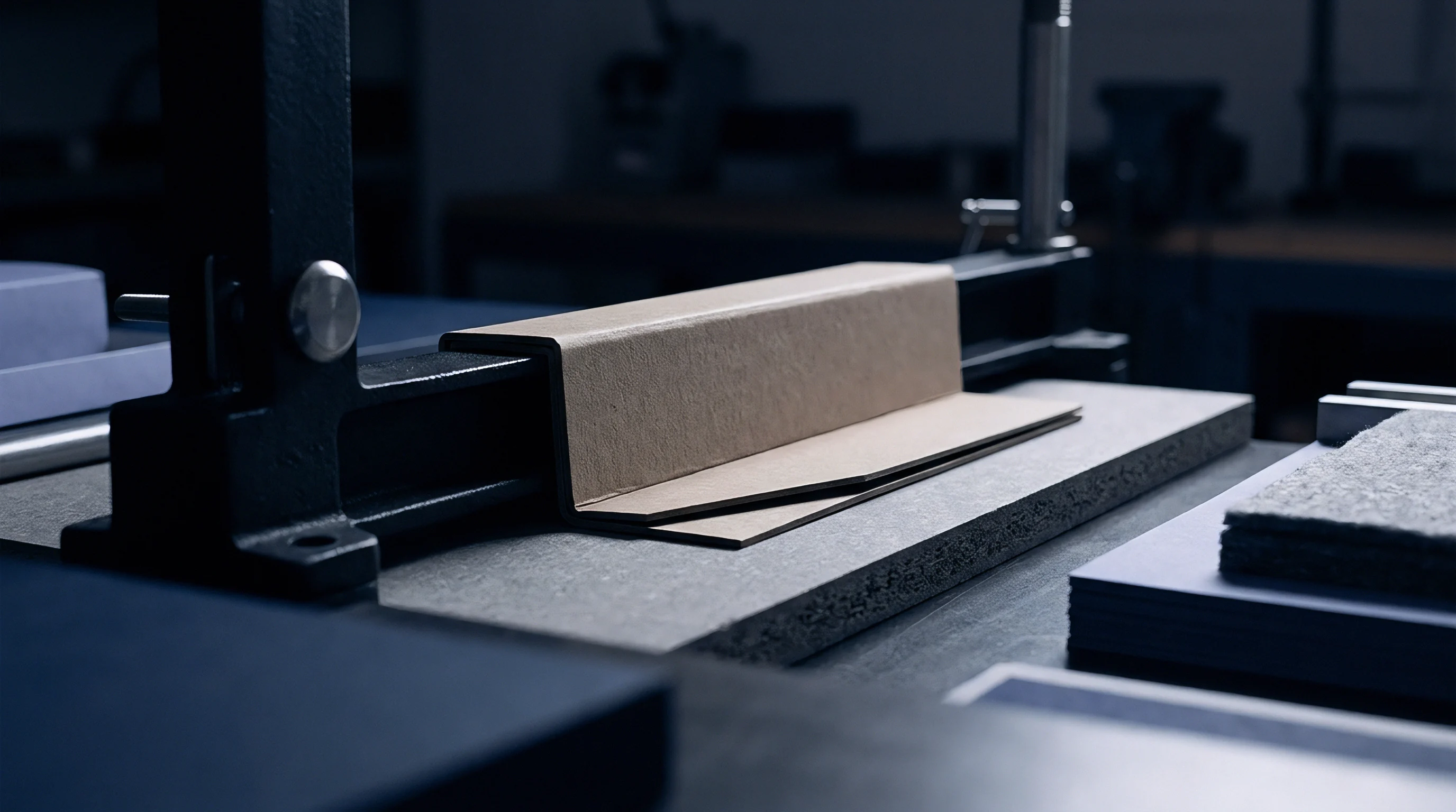
When Should Mandrel Bend Testing Replace Standard Peel Protocols?
Standard peel testing breaks down when flexible laminating films elongate plastically before crack initiation occurs. Mandrel bend testing replaces tensile peel fixtures when evaluating film detachment around tight radius folds on high-speed packaging machinery. The test wraps laminated specimens around calibrated cylindrical mandrels ranging from 1 mm to 10 mm in diameter, observing crack initiation under pure flexural strain.
Converting machinery subjects scorelines to severe compressive and tensile strains across narrow bend radii. Mandrel bend procedures subject the outer film layer to tensile elongation calculated by substrate thickness divided by mandrel diameter. If the film-board bond fails during bending, interfacial delamination surfaces as visible blistering along the bend line.
Calculated bending strains identify critical failure thresholds before converting full production lots. Thin paperboard substrates subjected to tight mandrel wraps simulate the geometric stress experienced inside folder-gluer transfer channels.

Peel Calibration Sequence
Calibrating mechanical test fixtures guarantees consistent interfacial force measurements across production shifts.
- Mount the load cell into the universal testing machine and warm up electrical components for 20 minutes prior to calibration.
- Perform a three-point deadweight calibration using certified masses covering 10% to 100% of full load cell capacity.
- Align the 90-degree sliding peel sled directly under the crosshead pin to prevent axial off-angle load vectors.
- Zero the system displacement reading while the peel grip rests flush against the rigid specimen holding plate.
Quality specifications must state that any delivery exhibiting an average steady-state 90-degree peel force below 120 N/m across five test strips shall be rejected without re-testing.
Joint
Creasing paperboard creates internal damage zones that permit clean 180-degree folding without surface cracking. Scoring rules depress the paperboard into female die channels, inducing z-direction shear stress and localized micro-delamination within internal paper plies. Laminated packaging adds a continuous polymer layer across this deformation zone.
The film must deform elastically and plastically without separating from the top coating layer during crease formation.
Scoring rule geometry determines interfacial strain magnitude. Excessive rule thickness or narrow die channels compress paperboard fibers severely, driving sharp shear forces directly across the film adhesive layer. This localized shear stress initiates micro-delamination along the crease axis before the blank reaches the folder-gluer line.
When the folder-gluer folds the flap 180 degrees, the pre-damaged film buckles outward, forming continuous blisters along the packaging edge.
Score depth shifts crack initiation. Deep scores reduce fold resistance torque but increase tensile strain on the outer film. High-speed cartoning machines fold flaps at rates exceeding 300 cartons per minute, applying impact loads that generate high strain rates within the interfacial adhesive layer.
Viscoelastic adhesives stiffen under high strain rates, transitioning from ductile energy absorption to brittle fracture propagation.
Scoreline Stress Distribution
Tensile stress reaches maximum concentration on the outer convex film surface during folding. Compressive stress dominates the inner fiber layers touching the internal carton volume. If the film interface possesses high fracture toughness, the outer fiber layers yield under tension while the film stretches continuously across the score line.
Moisture alters fiber compliance. Low ambient humidity stiffens cellulose fibers, increasing the force required to form a score line. Stiffer fibers generate higher spring-back forces after folding, placing continuous tensile stress on the adhesive boundary of the folded flap.
High humidity softens fibers, causing compressive buckling beneath the film during scoring passes.
Fiber tear marks joint integrity. A successful score line demonstrates clean internal board delamination across central plies while maintaining absolute interfacial cohesion between top fiber layers and the polymer film.
Score Optimization Parameters
Balancing creasing tooling dimensions preserves interfacial bonding during conversion.
- Scoring rule width must match paperboard thickness to distribute compressive force evenly without cutting top fibers.
- Matrix channel clearance accommodates displaced board bulk, preventing extreme localized shear stress along the film line.
- Creasing depth settings control internal delamination extent, lowering required fold torque without over-stretching outer film backings.
- Fold dwell duration permits stress relaxation within the polymer film layer, reducing elasticity-driven flap opening forces.
Crease integrity relies on maintaining internal paperboard delamination rather than interfacial film separation.
Scoring channel width rules dictate that total female groove width must equal 1.5 times board caliper plus rule thickness.
A simple rule of thumb states that if the outer film turns white or opaque along the score line during a manual ninety degree fold test, interfacial shear failure has initiated within the adhesive boundary.
Audit
Quality assurance verification of laminated paperboard relies on structured sampling protocols and quantitative failure classification. Receiving inspections that rely on manual thumb-peel tests introduce subjective operator bias, leading to un-detected adhesion failures reaching high-speed packing lines. Structured verification demands defined Acceptable Quality Limits, standard failure mode nomenclature, and statistical process monitoring across full production runs.
Sampling plans according to ISO 2859-1 define lot size, inspection levels, and acceptance thresholds. For a standard run of 50,000 laminated cartons, General Inspection Level II specifies a Sample Size Code Letter K, requiring 125 individual samples pulled across the entire press run. Testing these samples under 90-degree peel configurations establishes statistical capability indices (Cpk) for interfacial toughness.
Failure mode categorization provides direct feedback to converting press operator controls. Clean interfacial separation indicates chemical or surface energy deficiencies, whereas substrate fiber tear confirms adequate interfacial strength exceeding internal paperboard cohesion.

Failure Mode Classification Schema
Standardizing failure definitions allows converting engineers to isolate root causes during high-speed production runs.
- Type A Interfacial Separation occurs when the adhesive cleanly releases from the polymer film face without adhesive transfer or surface fiber disturbance.
- Type B Cohesive Adhesive Splitting leaves visible adhesive residue on both the film face and the paperboard top coating after separation.
- Type C Substrate Fiber Tear exhibits total structural failure within the paperboard z-direction plies, leaving dense fiber networks adhered to the film strip.
- Type D Film Backing Elongation involves severe plastic necking and rupture of the polymer film prior to interfacial crack initiation.
Uncured adhesive destroys batch cohesion. Receiving departments reject lots exhibiting Type A or Type B failure modes below specified peak force values.

Worked Verification Case
A converting facility processes a 100,000-carton production run of solid bleached sulfate board laminated with 12-micron metallized PET film for refrigerated food packaging. The quality control plan requires verifying 90-degree peel adhesion values and failure mode distribution to prevent field delamination in high-humidity cold chains.
Assume a lot size of 100,000 units. ISO 2859-1 Normal Single Sampling Level II assigns Sample Size Code Letter L, requiring 200 physical test specimens pulled at equal intervals during the converting run. The contractual specification mandates an average 90-degree peel force of not less than 150 N/m, with an Acceptable Quality Limit (AQL) of 0.65% for Type A or Type B failures occurring below 100 N/m.
Testing 200 specimens yields the following empirical data:
- 188 specimens exhibit Type C Substrate Fiber Tear with peak forces ranging between 165 N/m and 210 N/m.
- 8 specimens exhibit Type D Film Elongation with peak forces exceeding 190 N/m.
- 4 specimens exhibit Type A Interfacial Separation with peak peel forces recorded at 88 N/m, 92 N/m, 95 N/m, and 98 N/m respectively.
According to ISO 2859-1 Table 2-A, for Code Letter L and AQL 0.65%, the acceptance number is 3 non-conforming units, and the rejection number is 4 non-conforming units. Because 4 specimens failed to meet the 100 N/m threshold and exhibited Type A failure modes, the entire 100,000-carton lot reaches the rejection limit. Statistical process analysis identifies corona discharge decay on the metallized film roll stock as the root cause, occurred during press idle time between shifts.
Skipping batch receiving checks allows un-bonded film lots to reach automated cartoning lines, where flap debonding causes line jams costing thousands of dollars per hour in down-time.

Ledger
Lamination choices dictate converting cost structures, waste generation, and end-of-life recycling liabilities. Adding a film lamination pass increases unit cost through direct material expenditure, extra press passes, and elevated spoilage rates. Converting managers compare film lamination against liquid barrier dispersion coatings to meet physical performance demands at minimum landed cost.
Waste arithmetic accounts for both make-ready setup scrap and running spoilage. Wet-bond lamination lines require significant web travel length during temperature stabilization and nip pressure adjustment, losing hundreds of meters of board during bring-up. Running waste scales with speed fluctuations, splice pauses, and corona unit trips.
Non-conforming lamination rolls scrapped late in the converting sequence carry accumulated costs of board, ink, and press time.
Extended Producer Responsibility fees penalize multi-material packaging formats that impede cellulose fiber recovery. Regulations such as the EU Packaging and Packaging Waste Regulation impose eco-modulated fees based on recyclability grading protocols. Laminated paperboard containing non-soluble plastic films exceeding 5% total mass faces significant financial penalties or complete bans from municipal paper recycling streams.

Pass and Waste Cost Structure
Direct economic comparisons evaluate total landed cost per thousand finished sheets across competing surface barrier passes.
| Pass Type | Added Pass Cost per 1,000 Sheets (USD) | Make-Ready Waste (Sheets) | Running Spoilage Rate (%) | Cepi Recyclability Score | EPR Fee Category |
|---|---|---|---|---|---|
| 12-Micron BOPP Thermal Lamination | 42.50 | 350 | 2.2 | Fail (<85% Fiber Recovery) | High Penalty Tier |
| 15-Micron PE Extrusion Coating | 28.00 | 800 | 3.5 | Pass with Residuals | Standard Tier |
| Water-Based Acrylic Barrier Varnish | 14.20 | 100 | 0.8 | Pass (>95% Fiber Yield) | Preferred Green Tier |
| Solventless Polyurethane Film Lamination | 38.00 | 450 | 1.8 | Pass with Debonding Step | Medium Penalty Tier |
Low line speeds reduce yield. Operating laminating equipment below optimal thermal cross-linking speeds increases energy consumption per unit run. Solventless adhesives require 24 to 48 hours of room-temperature curing prior to die-cutting, adding work-in-progress inventory holding costs and extending job lead times.
The Cepi Recyclability Test Method Version 2 sets a strict minimum 95% coarse accept fiber yield threshold for packaging entering standard paper recycling mills.
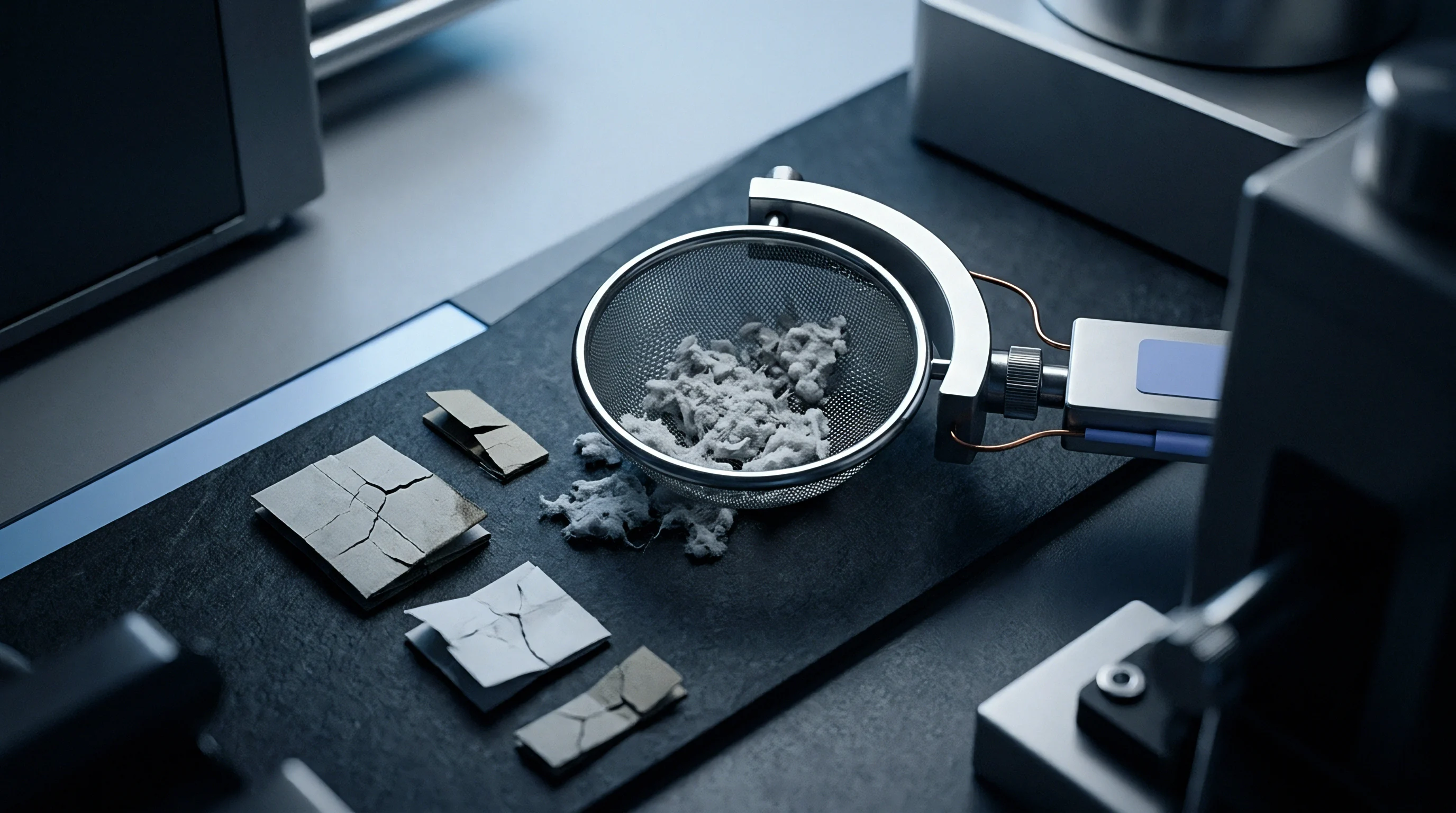
Recyclability rules dictate film removal. Packaging schemes demand that plastic films pass cleanly through coarse pulper screens without breaking into micro-plastics that clog paper machine wires. Interfacial adhesives that release cleanly during neutral aqueous repulping at 40°C allow the cellulose fibers to disperse fully, avoiding landfill penalties while preserving paperboard value.
Selecting water-dispersible laminating adhesives balances high operational fracture toughness during carton conversion with rapid interfacial debonding inside industrial recycling pulpers, securing lower Extended Producer Responsibility fee tiers across regional distribution networks.