Verifying Board Caliper before Cutting Brass Embossing Tooling
Verifying true substrate caliper under standard foot pressure before cutting brass embossing tooling prevents fiber shearing, smashed matrixes, and costly die remakes.
Gauge
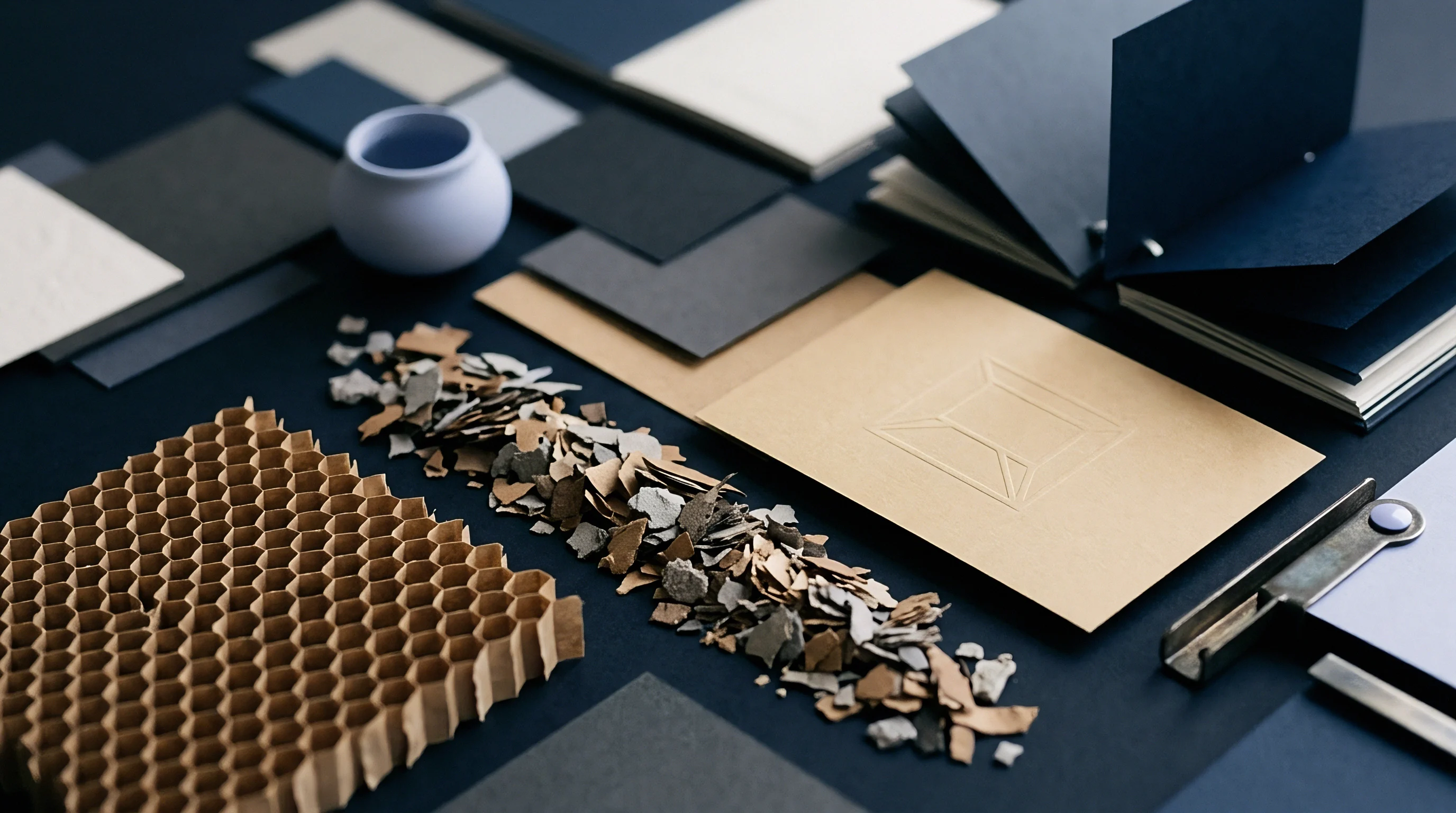
When an anvil micrometer lands on double-coated cartonboard, it compresses the clay coating before reading sheet caliper. That initial impression creates an immediate discrepancy between the physical board sitting on the press feeder and the electronic CAD drawing sent to the CNC engraving spindle. Mechanical micrometers built for paperboard testing exert specific spring pressures designed to collapse micro-voids inside the internal fiber network.
When specifying brass embossing tooling, male land and female recess depths depend on the board’s volumetric thickness under actual press impression, not the uncompressed optical bulk listed in sales literature.
Paperboard thickness readings vary significantly depending on the test method a converter uses. ISO 534 mandates a static pressure of 100 kilopascals applied through a circular foot with an area of 200 square millimeters, while TAPPI T411 specifies 50 kilopascals using a smaller contact foot. On a 450-micron folding boxboard, the difference between these standard methods routinely shifts caliper readings by 12 to 18 microns.
If a die cutter programs a CNC gravure router to cut female embossing depth off TAPPI T411 data, the finished die will stand too tall for stock measured under ISO conditions ~ crushing board structure, splitting fibers along relief shoulders, and wearing out the counter-die prematurely.
ISO test standards apply double the static foot pressure of TAPPI methods, compressing paperboard surface structures by up to eighteen microns before recording a final reading.
Internal morphology determines how board caliper behaves under press pressure. Solid Bleached Board, made entirely of bleached chemical pulp, has high internal density and uniform z-directional compressibility. Folding Boxboard places mechanical pulp between outer chemical pulp layers, yielding higher bulk that compresses unevenly under local shear.
White Lined Chipboard relies on recycled post-consumer fibers, creating pockets of variable density and uneven moisture absorption across the sheet. A single depth specification cut into brass will not perform identically across these three substrate families, even if lab reports show identical nominal calipers.
Moisture content drives immediate caliper shifts on the plant floor. Paperboard held at 50 percent relative humidity and 23 degrees Celsius retains stable fiber bonding. Moving that stock onto an unconditioned press floor operating at 65 percent relative humidity causes hygroscopic cellulose fibers to swell radially, adding three to five percent to total sheet caliper within six hours.
If brass tooling is engraved to match a dry swatch sample, adding 20 microns of moisture bulk on press creates severe pinch points along bevel borders, cracking the top clay coating and exposing underlying raw fibers.
| Paperboard Substrate Type | Nominal Caliper Range (μm) | ISO 534 Caliper Shift vs TAPPI T411 (%) | Z-Directional Compressibility at 15 MPa (%) | Moisture Regain Caliper Expansion (% per 10% RH) |
|---|---|---|---|---|
| Solid Bleached Board (SBB / SBS) | 300 – 600 | -2.8 | 11.4 | +0.8 |
| Folding Boxboard (FBB – Mechanical Core) | 350 – 800 | -4.2 | 18.6 | +1.2 |
| White Lined Chipboard (WLC / CRB) | 380 – 750 | -5.1 | 22.1 | +1.6 |
| Coated Kraft Back (CKB / SUS) | 400 – 850 | -3.1 | 14.2 | +0.9 |
Static dead-weight micrometers on the receiving dock check every batch before approving brass tool production. Lab techs take ten readings across the cross-machine direction on three separate sample sheets per pallet, averaging the results into a distribution profile. Relying strictly on mill test certificates introduces systematic errors into toolpath programming.
Mills gauge thickness right after the calendering stack on the paper machine, long before thermal contraction and moisture equilibrium stabilize. The caliper on a mill docket reflects an idealized state that rarely survives transit and warehousing.
Accurate mechanical readings demand strict operator discipline around dwell time and foot placement. Dropping the micrometer foot too quickly onto a sheet edge creates an impact spike that artificially lowers the reading by deforming internal fiber matrix structures. The foot must descend under gravity alone, resting on the sheet for precisely two seconds before taking the digital reading.
Readings taken within 50 millimeters of a mill-trimmed edge should be disregarded, as slitting wheels compress the sheet boundary and distort the true profile.
Surface coatings add another layer of complexity to caliper checks before die cutting. Polyethylene barriers, functional varnishes, and heavy mineral pigment coatings alter the balance between compressible fiber volume and non-compressible surface mass. A 400-micron board carrying a 20-gram-per-square-meter extrusion layer responds differently under pressure than an uncoated sheet of identical overall thickness.
Because non-compressible surface layers absorb zero vertical force, they transfer 100 percent of platen pressure directly into the underlying fiber core. Tool designers who lump coating thickness together with structural fiber caliper produce dies with tight relief clearances, causing micro-cracking along deep embossing lines.
Paperboard from multiple reels naturally drifts within an agreed five percent tolerance band, leaving press operators to adjust bed pressure during make-ready to compensate for variations up to 22 microns across a single shipment.
Geometry
High-speed CNC engraving spindles carve three-dimensional relief channels into solid brass plates using carbide endmills down to 0.1 millimeter diameters. Channel geometry depends on exact mathematical ratios calculated from verified board caliper. A female brass die relies on three primary physical parameters: relief depth, shoulder draft angle, and corner radius.
If relief depth matches the uncompressed board caliper, the stock undergoes 100 percent volumetric displacement at maximum stroke, shearing internal fibers and punching straight through the carton surface.
Programming relief depth requires setting a compression factor tailored to the substrate’s bulk density. For standard multi-level embossing on folding boxboard, female cavity depth is set to compress the sheet to between 65 and 75 percent of its static caliper at peak impression stroke. A 500-micron board needs an engraved female depth of 350 to 375 microns for deep sculptured areas, with shallow background details stepped at 150 to 200 microns.
Pushing compression below 60 percent breaks the hydrogen bonds between cellulose fibers, triggering delamination and board feathering that shows up as unsightly white flaking along printed borders.
Female die depth programmed to seventy percent of verified board caliper provides maximum visual relief without exceeding the structural shear limit of internal fiber networks.
Draft angles on cavity walls dictate how smoothly paperboard releases from brass tooling during the open cycle. Vertical 90-degree walls fail in commercial finishing operations because pressurized board fibers expand laterally into metal micro-textures, locking the sheet inside the tool. Carbide cutters need to bevel cavity walls at angles between 30 and 60 degrees relative to the vertical axis.
Steep angles concentrate shear forces along a narrow line, while wider draft angles spread impression pressure across a broader surface area, protecting the surface coating from rupture.
| Embossing Effect Profile | Target Cavity Depth Formula | Draft Angle Range (Degrees) | Male Counter Clearance Calculation | Recommended Counter Material |
|---|---|---|---|---|
| Single-Level Flat Top | Verified Caliper × 0.70 | 35 – 45 | Female Cavity Width – (2 × Caliper × 0.85) | Glass-Fiber Epoxy Resin |
| Multi-Level Sculptured | Verified Caliper × 0.60 to 0.80 | 30 – 60 | Step-down toolpath offset by 0.80 × Caliper | Milled Brass Counter |
| Micro-Embossing / Texture | Verified Caliper × 0.25 | 60 – 75 | Zero male counter (Flat anvil pressure) | Hardened Steel Anvil Plate |
| Blind Debossing | Verified Caliper × 0.50 | 45 – 60 | Direct female penetration without matrix | Polyurethane Underlay |
Counter-die matrix preparation is the second half of the physical geometry equation. The male counter tool forces paperboard up into the female cavity, so its dimensions must account for board caliper on all lateral sides. The offset clearance between the male force land and female cavity wall needs to equal 80 to 90 percent of verified board caliper.
Fiber density dictates clearance. Match a 400-micron sheet with a counter-die milled with a 300-micron wall clearance gap, and the board pinches laterally ~ scuffing the coating and warping surrounding flat panels.
Relief shear occurs during high-speed production runs whenever clearance drops below ten percent of nominal sheet thickness. Precision counters are made from glass-fiber epoxy plates, liquid photopolymer cast off the female brass die, or direct CNC-milled brass counter plates. Matched brass-to-brass tooling sets offer outstanding dimensional stability across long production runs, but original toolpath calculations must be spot on.
A milled brass counter leaves zero margin for error on press. If delivered board comes in 30 microns thicker than the sample measured for tooling design, a brass counter die will smash the press platen or fracture chasing bed screws.
Corner radii cut into the bottom of female cavities dictate how stress spreads across paperboard fibers. Sharp interior right angles create severe stress concentration points right where impact strikes. Carbide cutters need to bevel internal root corners with a minimum radius equal to 25 percent of total board caliper.
Smooth internal radii help cellulose fibers slide and fold into the relief contour without tearing the top linerboard. Shallow dies lose definition; deep grooves shear paperboard. Balancing cavity depth against draft angle and root radius keeps high-definition detail sharp while maintaining full structural carton strength.
Toolpath calculations must account for how cellulose structures spring back after impression. Paperboard doesn’t stay at its fully compressed thickness after exiting the platen nip. Internal spring-back causes the board to rebound by 15 to 25 percent of compressed depth within seconds after pressure release.
Tool designers cut female cavities slightly deeper than the target visual depth to compensate for this predictable recovery, provided the surface fiber strain limit isn’t breached.
How Does Fiber Density Shift Male Clearance?
High-density solid bleached board needs wider lateral clearance gaps than low-density mechanical pulp board because it resists sideways displacement. In the die nip, tightly bound chemical pulp fibers cannot collapse inward, forcing excess mass sideways into the draft clearance zone. Mechanical pulp board contains compressible air pockets that absorb vertical force without generating significant lateral push.
As a result, tool designers expand male counter clearance values by 10 percent when moving from folding boxboard to solid bleached board grades of identical static thickness.
Swapping substrate grades on fixed tooling without adjusting clearance geometry causes immediate defect issues on the converting floor. The list below outlines main operational failures resulting from mismatched clearance geometry and unverified paperboard caliper.
- Fiber Shear Rupture occurs when female cavity depth exceeds eighty percent of board thickness, forcing male counter edges to cut through the board structure like a blanking tool.
- Coating Flaking Defect arises from steep draft angles under forty degrees paired with insufficient wall clearance, scraping mineral coatings off the surface during sheet ejection.
- Halo Distortion Distortion develops around relief perimeters when excessive male counter displacement draws board mass from flat panel areas, causing severe sheet warping.
- Detail Loss Defect happens when female cavity clearance exceeds 110 percent of board caliper, preventing male lands from exerting sufficient compaction force to set internal fibers.
Under standard commercial converting agreements, the die maker accepts financial responsibility for recutting brass tooling only when delivered die dimensions deviate by more than five microns from approved CAD specifications submitted by the buyer.
Platen
Lock-up chases holding multi-up brass dies undergo measurable thermal strain when heated past ambient plant temperatures. Press operators run brass embossing tools at temperatures between 80 and 120 degrees Celsius to soften lignin binders within paperboard fibers, enabling permanent plastic deformation without cracking printed ink. Brass has a high coefficient of thermal expansion, expanding approximately 18 x 10^-6 per degree Celsius.
A 600-millimeter-wide solid brass die block heated from an ambient 20 degrees Celsius to an operational 100 degrees Celsius expands by nearly 0.9 millimeters across its horizontal layout, shifting multi-up image register entirely off printed target marks.
Thermal expansion distorts vertical relief geometry alongside lateral register positions. Brass dies expand uniformly in three dimensions, meaning vertical engraved relief depths grow taller as the chasing bed warms up. A female cavity engraved to a precise 400-micron depth at room temperature expands to 402.5 microns at 100 degrees Celsius, while the underlying steel chase plate expands at less than half that rate.
That difference alters the exact impression force exerted at peak stroke. Operators must bring heated chasing beds to full thermal equilibrium for at least 45 minutes before locking down register and starting make-ready pressure calibration.
Thermal expansion increases brass die dimensions by nearly one millimeter across a large-format bed, requiring full thermal stabilization before final pressure calibration.
Equalizing impression force across multi-up layouts takes careful tissue patch-up work on the press bed. Between minor machining variations across platen beds and caliper fluctuations across wide webs, impression pressure is rarely uniform across the entire sheet surface. Operators slide thin make-ready tissue papers, ranging from 20 to 40 microns in thickness, behind the steel backing plate to build up pressure in under-embossed zones.
Adding a single 30-micron tissue sheet behind a brass die increases local pressure by several megapascals, noticeably altering how deeply the male counter penetrates the board cavity.
Tracking press setup times on heated chasing beds prevents tool damage during initial pressure bring-up. Bringing up pressure requires a disciplined step-by-step procedure to avoid smashing new brass tooling against miscalibrated male counters. The numbered sequence below outlines the exact bring-up procedure required for high-speed flatbed embossing presses.
- Mount brass female dies into the heated chasing plate using heat-resistant mechanical toggle clamps torqued to spec.
- Energize chasing bed heating zones and wait 45 minutes until internal sensors confirm stable operating temperatures across all quadrant positions.
- Attach liquid photopolymer matrix material or pre-milled counter plates to the press bed, applying a slow impression stroke to cast accurate male counter profiles.
- Back off total platen pressure adjustments by 0.50 millimeters before running the first test sheet through the impression nip.
- Increase platen tonnage incrementally in 20-micron steps, inspecting first-off sheets under low-angle grazing light after each impression pass.
- Apply local make-ready tissue patches behind the steel bed plate to equalize shallow impression areas across all multi-up packaging positions.
- Lock platen position controls and run fifty waste sheets at full machine operational speed to confirm thermal and mechanical registration stability.
First-off sheet inspection must take place under low-angle grazing light positioned at 15 degrees relative to the sheet plane. Overhead fluorescent lighting masks micro-fractures, shadow distortions, and subtle depth variations across sculptured emboss surfaces. Operators examine the reverse side of the embossed board to verify that male counter impression marks are clean, uniform, and free from sharp cut marks that indicate excessive stroke pressure.
Sharp cut lines on the reverse linerboard indicate that impression tonnage is excessive or male counter clearance is narrower than actual board caliper.
Dwell time at peak stroke dictates how effectively heat penetrates paperboard fibers from the brass die. High-speed automatic platens running at 7,000 sheets per hour offer a dwell time of only a few milliseconds at maximum compression nip. At these production speeds, heat transfers only into the top coating layer, leaving the internal core cold and springy.
To set fibers permanently at high speeds, operators must increase chasing bed temperatures slightly to accelerate heat transfer, or select high-density brass alloys with elevated thermal conductivity ratings.
Unconditioned board that expanded mid-shift crushed the male counter matrix and split the printed carton surface across twelve thousand finished units, incurring a four-thousand-dollar tooling recut charge.

Tolerance
Mill test certificates quote nominal board thickness derived from single-point laboratory sampling off master reels. In production, paperboard exhibits systematic caliper variations both along the machine direction and across the web profile. A paper machine running at 800 meters per minute experiences minor micro-barring at the wet-end press section, headbox slurry pulsation, and uneven thermal profiles across drying cylinders.
These process variations produce a continuous caliper ripple across the finished board roll, establishing a baseline tolerance band that converting operations must manage.
Industry standards like DIN 53121 allow paperboard manufacturers a broad caliper variance tolerance band of plus or minus five to eight percent from target nominal specs. On a 500-micron board, an eight percent tolerance allows delivered board thickness to drift between 460 and 540 microns across different pallets within the exact same production lot. Mill certificates quote averages.
This 80-micron real-world spread represents a massive mechanical change for rigid brass embossing tools designed with fixed 30-micron draft clearances and precise male matrix offsets.
Pallet-to-pallet variance presents severe operational challenges for automated conversion lines. When an operator finishes a pallet sitting at the low end of the tolerance band (460 microns) and immediately feeds stock sitting at the high end (540 microns) without adjusting platen pressure, board splitting is instantaneous. The additional 80 microns of uncompressed fiber creates overload forces within the closed impression nip ~ crushing fibers, damaging brass die shoulders, and stalling high-speed platen drive motors.
An eighty-micron thickness spread across a single board order will smash fixed brass die clearances if platen pressure remains unadjusted between pallet changes.
Moisture hysteresis expands caliper variation further during long-term storage in customer warehouses. Paperboard absorbs ambient moisture rapidly once protective stretch-wrap is removed on the press floor. A 10 percent shift in ambient humidity alters sheet dimensions nonuniformly, with sheet edges swelling far faster than the compressed center of the pallet stack.
Uneven moisture uptake produces wavy edges and tight centers, meaning sheet caliper varies across a single 720 x 1020 millimeter paperboard sheet before it ever reaches the embossing die nip.
Managing caliper variation requires structured incoming inspection protocols and clear decision frameworks for press operators. The checklist below defines the physical parameters that must be evaluated on incoming paperboard lots before releasing brass tooling for final production cutting.
- Cross-Web Caliper Spread must not exceed three percent of nominal thickness across ten equidistant measuring points along the master sheet width.
- Moisture Content Baseline must measure between 5.5 and 7.0 percent using calibrated radio-frequency moisture probes inserted into core stack zones.
- Z-Directional Tensile Strength must meet minimum mill specification thresholds to ensure internal fiber layers resist delamination under deep relief strain.
- Surface Smoothness Profile evaluated via Bendtsen or Parker Print-Surf methods must remain uniform to prevent local pressure variations across fine embossing detail.
Statistical process control tracks caliper drift across large packaging production runs. Plotting micrometer readings on x-bar control charts lets QA technicians spot gradual trends in board thickness before catastrophic tooling failures occur on press. If measurement trends show board thickness drifting steadily toward the upper specification limit, press operators reduce platen impression tonnage proactively or lower chasing bed temperatures slightly to reduce thermal expansion effects, maintaining clean relief definition without risking fiber fracture.
Does the mill guarantee a tight three-percent caliper tolerance band across multi-reel shipments without demanding an additional ten-percent price surcharge on the base paperboard order?
Settlement
Scrapping an engraved brass die set because relief depths shear paperboard fibers drops immediate financial loss onto the converter who signed the tooling specification. Engraved brass embossing tools represent significant capital expenditure, with multi-up sculptured die sets costing between two thousand and fifteen thousand dollars depending on visual complexity, bed format size, and counter-die matrix technology. Recutting dies halts production.
When a tool fails on press, direct losses go far beyond the physical brass plate cost ~ including press downtime billed at hundreds of dollars per hour, ruined printed sheets, and missed client delivery deadlines.
Contractual liability allocation hinges on which party verified and approved baseline substrate caliper before CNC toolpath generation. If a brand buyer specifies a 450-micron board on the job docket but the converter orders a 500-micron board from the mill to boost package rigidity without notifying the die cutter, the converter absorbs 100 percent of all recut charges and downtime expenses. Toolmakers cut strictly to the electronic dimensions provided in signed approval dockets.
If physical board delivered to the press floor matches signed drawing specs, any operational failure on press sits entirely with the converting plant.
| Failure Driver | Primary Defect Observed | Direct Financial Exposure Item | Responsible Party Under Standard Contracts |
|---|---|---|---|
| Unverified Caliper Increase | Fiber shear, board splitting | Die remake, ruined print stock, press downtime | Converter / Buyer (Order Sign-off) |
| Die Engraving Dimension Error | Lacks relief depth, poor definition | Die recut charges, set-up waste scrap | Die Maker / Engraving Supplier |
| Excessive Mill Caliper Drift | Intermittent crushing and faint emboss | Sorting costs, slow machine running speeds | Paperboard Mill (if outside spec limit) |
| Thermal Expansion Overload | Register mis-alignment, smashed matrix | Counter-die remake, make-ready labor | Converting Press Room Operations |
Negotiating credit adjustments with paperboard mills for off-caliper board requires solid documentation captured at the exact moment of delivery. Mills reject claims for ruined tooling or press downtime if the converter failed to measure and log board caliper prior to running sheets through the finishing press. Quality assurance managers must retain original mill roll tags, sample sheets from unembossed pallets, and documented micrometer log sheets showing statistical deviation outside agreed DIN or ISO standard limits.
Without physical sample sheets and calibrated test logs, mill claims departments routinely dismiss disputes as ordinary press operator error or improper make-ready setup.
Amortizing tooling costs across multiple packaging reorders requires strict tool maintenance and storage practices inside the converting plant. Brass dies exposed to high humidity and corrosive chemical atmospheres undergo oxidation, forming a rough copper carbonate patina that alters micro-etched surface textures and increases friction during sheet ejection. After completing a production run, operators must clean brass dies with non-abrasive solvent cleaners, spray them with protective light oil coatings, and store them inside climate-controlled rooms maintained at low relative humidity.
Proper storage preserves precise tool geometry, ensuring original clearance calculations remain valid when the job returns for reprint cycles months later.
Waste ledger arithmetic proves that spending twenty minutes verifying board caliper on the receiving dock saves tens of thousands of dollars in scrapped print sheets and emergency tooling remakes downstream. A single ruined pallet of five-color offset printed packaging board carrying functional barrier coatings represents a massive financial loss before it ever reaches the embossing platen. Verifying thickness ahead of die cutting protects the entire investment in print prepress, ink, varnish, and machine time.
Precise caliper verification turns finishing from an unpredictable craft into a predictable, repeatable, and profitable engineering discipline.
A brass die cut to match real board thickness runs clean on first bring-up without tearing fibers or smashing press beds.