Managing Thermal Expansion in Brass Embossing Dies
Managing thermal expansion in brass embossing dies requires pre-scaling vector artwork by calculating precise isotropic expansion across operating press temperatures.
Heat
An operating temperature of 130 degrees Celsius expands an engraving block predictably along every spatial axis. Brass possesses a coefficient of thermal expansion near 18.5 micrometers per meter per kelvin. When a flat engraving plate measuring 600 millimeters across major dimensions reaches working conditions on a hot foil stamping press, physical dimensions increase by more than one full millimeter.
Ignoring this physical reality guarantees misregistration against pre-printed graphic elements. Copper and magnesium exhibit lower and higher thermal response rates respectively, positioning brass as a material that demands precise thermal calculation during die design and setup.
Heat energy flows from resistance heating rods inside the press chase through the steel backing plate and into the brass block. Thermal equilibrium is not achieved instantly. Temperature distribution remains uneven during press warm-up cycles, creating transient localized distortions across the engraved image area.
Brass expands fast.

Thermal Expansion Coefficients across Die Alloys
Free-cutting brass grade CuZn39Pb3 exhibits an expansion rate of 18.5 micrometers per meter per kelvin at ambient press room baseline conditions. Selecting die materials requires evaluating thermal expansion rates alongside thermal conductivity and mechanical wear resistance across long production runs.
| Material Grade | Coefficient of Thermal Expansion (10⁻⁶/K) | Thermal Conductivity (W/m·K) | Specific Heat Capacity (J/kg·K) | Machinability Index (Brass = 100) |
|---|---|---|---|---|
| Free-Cutting Brass (CuZn39Pb3 / CW614N) | 18.5 | 115 | 380 | 100 |
| Engraver Copper (Cu-HCP / C10300) | 16.5 | 390 | 385 | 25 |
| Photoengraving Magnesium (AZ31B-H24) | 26.0 | 96 | 1020 | 500 |
| Tool Steel (1.2343 / H11) | 11.8 | 25 | 460 | 35 |
Magnesium dies expand significantly faster than brass under identical heat loads, growing 26.0 micrometers per meter per kelvin. Steel chase frames grow at less than two-thirds the rate of brass, creating physical interface tensions whenever dies are rigidly bound on all four sides. The mechanical mismatch between steel chases and brass dies generates compressive stress within the die body when clamping systems fail to yield.
ISO 12647 registration criteria require impression placement within 50 micrometers of printed trap margins.
Temperature Gradients in Hot Embossing Presses
Platen resistance heating elements supply energy through the heavy steel chase, creating a distinct thermal difference between the base block and the engraving surface. Surface cooling occurs continuously as cold paperboard enters the platen press, absorbs thermal energy during the dwell phase, and carries heat away upon sheet ejection. A brass die set to 140 degrees Celsius platen temperature may drop five to eight degrees at the engraving face during continuous high-speed operation.
Cold platens ruin alignment. Operating a press at 120 cycles per minute creates a dynamic thermal balance where heat replacement from internal heating elements matches surface energy losses to paperboard and air convection. Lowering press speeds allows the engraving face temperature to rise toward platen equilibrium, causing the brass die to expand further during mid-run speed adjustments.
Thermal gradients also form horizontally across large platen areas. Edge zones radiate heat to surrounding press frames, causing perimeter die areas to operate at lower temperatures than center areas. Multi-zone chase heating systems reduce these horizontal temperature variations by delivering higher electrical wattage to perimeter zone heaters.
Uncompensated dies misalign. Temperature monitoring requires focused optical infrared sensors aimed directly at die relief surfaces rather than relying solely on thermocouples embedded deep inside chase backing plates.
Failing to account for temperature differentials across the die face results in uneven embossing depth, edge cracking, and permanent thermal distortion of expensive brass blocks.

Scale
Calculating dimensional artwork compensation prevents misregistration between previously offset-printed sheets and blind embossing passes. Vector geometry in digital design files is modified prior to CNC engraving to ensure the expanded die matches printed target dimensions at operating temperature. Without artwork pre-scaling, a brass die engraved at exact nominal dimensions expands beyond printed trapping zones during production runs.
Engraving precision matters.
Pre-scaling corrects the offset. The artwork compensation process scales digital artwork down by an exact percentage corresponding to expected thermal growth between room temperature vector prep and press operating heat.
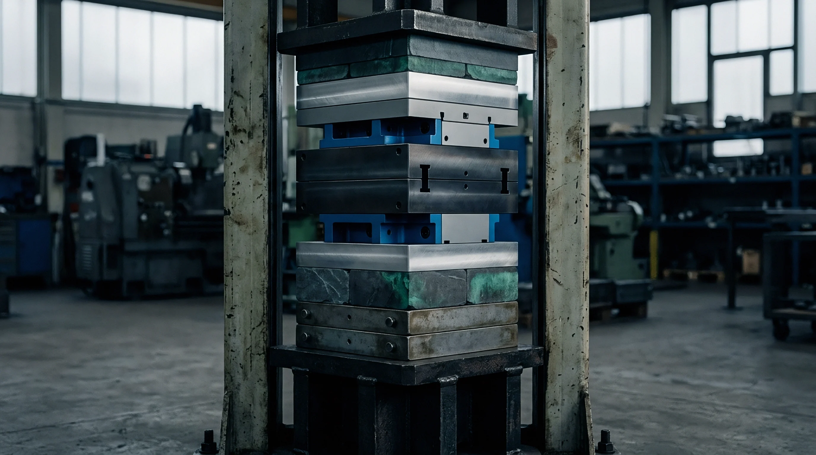
What CTE Variance Disrupts Fine-Detail Embossing Alignment?
A dimensional growth of 0.25 millimeters across a 500 millimeter sheet width shifts fine sculpted detail completely outside printed trapping boundaries. Fine-line foil stamping and sculpted combination embossing demand alignment tolerances within 0.05 millimeters. Uncompensated thermal expansion in brass tooling creates progressive misregistration that worsens linearly moving away from the sheet center line.
Cross-directional expansion acts independently from press-direction expansion. While paperboard stretches slightly under mechanical gripper tension in the run direction, brass expands isotropically in both planar directions. Artwork prep software applies differential scaling factors when paperboard hygroexpansivity interacts with thermal expansion from heated embossing passes.

Mathematical Artwork Compensation Formulas
Linear dimensional adjustments follow isotropic dimensional equations applied directly to vector art files prior to engraving. Calculating the required artwork scale factor uses the following primary expansion relationship:
Linear Expansion Equation ~ ΔL = L₀ × α × (T_work – T_room)
In this equation, L₀ represents the initial dimension at 20 degrees Celsius room temperature, α represents the linear coefficient of thermal expansion for brass (18.5 × 10⁻⁶ / K), T_work represents the die surface operating temperature in degrees Celsius, and T_room represents the ambient prep room temperature (20 degrees Celsius).
Consider a practical calculation for a folding carton embellishment die. Take a brass embossing die designed to finish a sheet area measuring 600.00 millimeters wide operating at 140 degrees Celsius in a press room maintained at 20 degrees Celsius. The temperature differential (ΔT) equals 120 Kelvin.
ΔL = 600.00 mm × (18.5 × 10⁻⁶ / K) × 120 K = 1.332 mm
The total physical expansion across the die surface equals 1.332 millimeters at 140 degrees Celsius. To ensure the die expands to exactly 600.00 millimeters on press, CAD operators apply a pre-shrink reduction factor to original vector artwork prior to CNC machining:
Pre-Shrink Scale Factor Equation ~ Scale Factor = 1 / (1 + α × ΔT)
Scale Factor = 1 / (1 + 18.5 × 10⁻⁶ × 120) = 1 / 1.00222 = 0.997785
Multiplying the 600.00 millimeter nominal graphic vectors by 0.997785 yields a pre-shrunk artwork dimension of 598.67 millimeters. Machining the brass die to 598.67 millimeters at room temperature ensures it expands precisely to 600.00 millimeters when heated to 140 degrees Celsius on the production floor.
At 140 degrees Celsius, a 600 millimeter brass embossing die expands by 1.332 millimeters across its major axis.
Calculating artwork pre-scaling factors for varied operating temperatures reveals substantial shifts in required vector geometry adjustments. The table below details exact artwork scaling targets across standard hot embossing operating regimes for brass tooling.
| Target Operating Temperature (°C) | Temperature Differential ΔT (K) | Thermal Expansion Rate (%) | Artwork Pre-Scale Factor | Vector Reduction on 500mm Die (mm) |
|---|---|---|---|---|
| 100 | 80 | 0.148 % | 0.998522 | 0.74 mm |
| 120 | 100 | 0.185 % | 0.998154 | 0.93 mm |
| 140 | 120 | 0.222 % | 0.997785 | 1.11 mm |
| 160 | 140 | 0.259 % | 0.997417 | 1.30 mm |
Complex multi-level brass dies incorporating sculptural relief require proportional three-dimensional artwork scaling. Depth engraving vectors must be pre-scaled along the Z-axis at identical rates to prevent relief angles from shifting steepness when heated platens expand the die body.
Die makers frequently assert that registration discrepancies arise from substrate dimensional instability rather than uncompensated artwork scaling errors at the pre-press stage.

Mount
Mechanical clamping fixtures accommodate linear thermal growth without bowing the die plate or generating compressive mechanical stress. Rigidly bolting a brass die to a cold steel chase on all four corners forces the thermal expansion movement inward, causing the die center to crown upward away from the chase. Bowing distorts impression depth.
A crowned die creates heavy impression center pressure while losing relief depth along outer edges.
Floating mounting arrangements eliminate die distortion. Allowing perimeter expansion while fixing exact position relative to press centerline preserves registration without plate crowning.

Centerline Locking Systems and Floating Chases
Dynamic keyways fixed at the geometric center force growth outward symmetrically toward all four plate margins. Centerline clamping prevents walk. Locating keys installed along central horizontal and vertical axes anchor the die center while perimeter toggle clamps hold the plate flush against the chase using spring-loaded or slotted expansion washers.
When heat enters the assembly, expansion pushes the outer edges outward into designed thermal clearance channels. The geometric center remains stationary relative to press sheet guide registers, maintaining equal registration distribution across both operator and drive side edges of printed sheets.
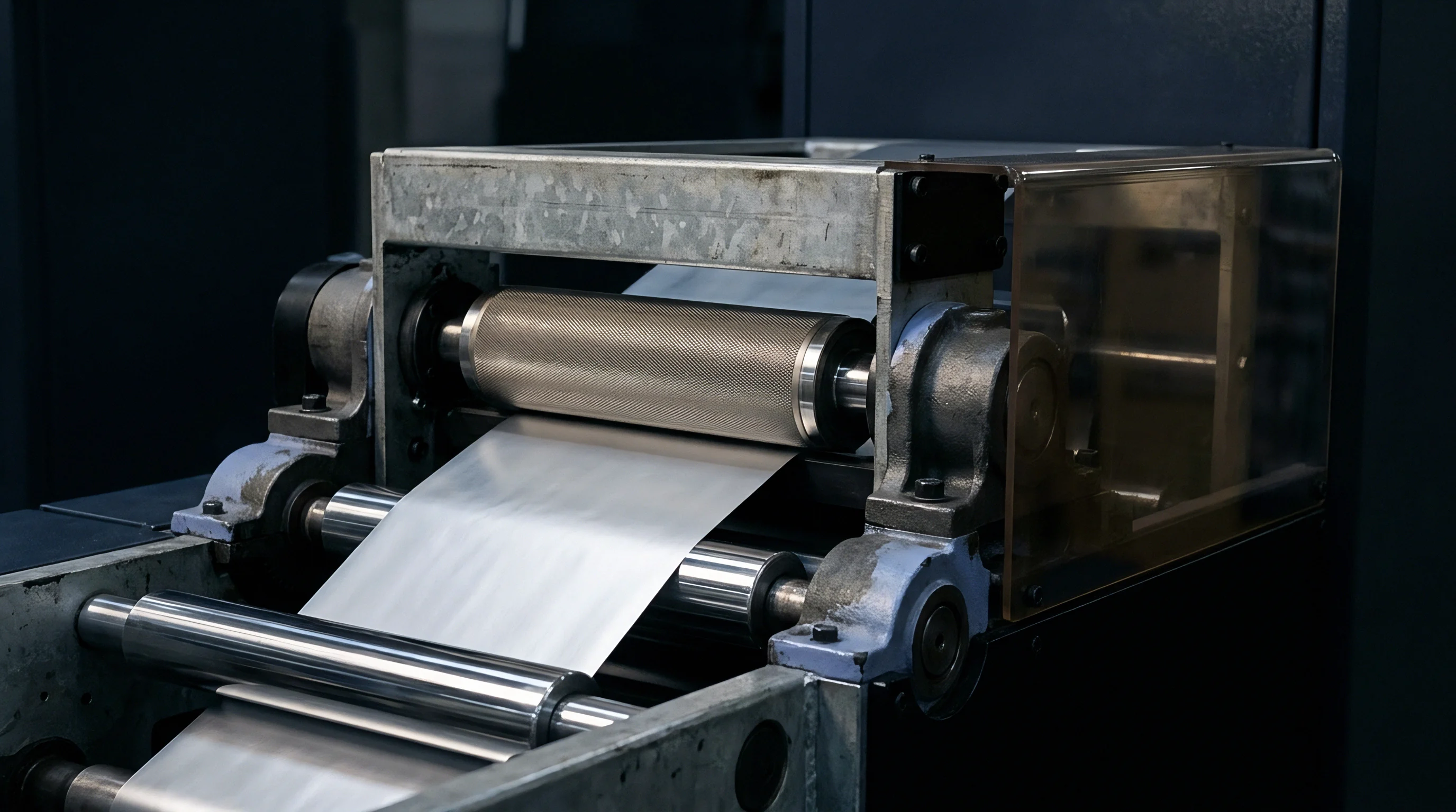
Thermal Relief Slots and Mounting Hardware
Machining perimeter relief channels into brass tooling prevents binding against heavy steel retention toggle clamps. Perimeter slots milled into die sides allow toggle clamps to maintain strong downward clamping force while sliding freely along the expansion vector plane.
- Corner Binding Cracks lock the outer corners of brass dies against rigid chase borders, inducing severe shear stresses that crack die corners during thermal cycling.
- Center Plate Crowning lifts the middle of the brass plate away from the platen backing by up to 0.30 millimeters, causing uneven depth density across embossed patterns.
- Sheared Retention Screws result from rigid perimeter bolting that fails to yield as brass thermal forces overcome the shear strength of steel fasteners.
- Platen Indentation Wear occurs when thermal crowning concentrates press impression tons onto narrow center die zones, permanently damaging chase plates.
Tooling geometry dictates fit. Fastener torque specifications for expansion clamps must balance clamping force against friction resistance to sliding. Excessive torque locks clamps, defeating expansion slots and creating internal plate strain.
Securing brass plates from the optical center outward allows uniform thermal growth while maintaining cross-directional registration integrity across long press shifts.
Disregarding thermal clearance requirements in chase clamping systems results in distorted tooling geometry and inconsistent impression force across production sheets.


Drift
Press stabilization cycles dictate how registration holds from first-off sheet sign-off through a full multi-thousand impression production shift. Starting press runs immediately upon reaching platen setpoint guarantees registration walk. Thermal equilibrium takes time.
A cold chase assembly absorbs heat gradually, causing continuous dimensional growth of brass dies during the first hour of press operation.
Shift-start procedures mandate controlled thermal soak periods before establishing initial press register approvals. Running make-ready sheets during thermal stabilization wastes expensive foil and paperboard substrates.
Heat Soak Cycles and Shift Start Procedures
Pre-heating chase assemblies for forty-five minutes before running make-ready sheets brings the entire mass to equilibrium temperature. Thermocouples mounted on platen surfaces frequently indicate target operating heat long before brass die blocks achieve steady-state conditions throughout their volume.
Establishing steady thermal state requires executing a standardized press bring-up sequence prior to first-off register sign-off:
- Mount brass dies into chase frames with perimeter expansion clearance checked using feeler gauges.
- Energize platen heating zones to target operating temperature while keeping press platens open.
- Dwell platen temperature at target setpoint for forty-five minutes to allow heat absorption into chase steel and brass die blocks.
- Close press platens into slow inching mode to equalize surface thermal energy across upper and lower chase structures.
- Verify surface temperature uniformity across all die quadrants using a calibrated infrared surface pyrometer.
- Run twenty-five test sheets to evaluate register placement against pre-printed target marks.
- Perform fine register adjustments on press chase micro-drives only after temperature readings stabilize across two consecutive checks taken fifteen minutes apart.

Substrate Moisture Loss and Paper Dimensional Shift
Radiated thermal energy during a dwell pass strips bound moisture from cellulose fibers, shrinking the paperboard substrate while metal tooling grows. Moisture loss shrinks paperboard. High ambient humidity in converting plants increases paper moisture content, amplifying shrinkage effects when paperboard hits 140 degree embossing platens.
Substrate shrinkage acts directly opposite to brass thermal expansion. While the brass die expands by 0.22 percent under operating heat, paperboard substrate can shrink by 0.10 to 0.15 percent cross-directionally due to rapid moisture evaporation during impression dwell. The total operational gap between artwork target lines and die impression lines equals the combined sum of brass expansion and paperboard shrinkage.
Paperboard moisture loss under heated platens compounds thermal mismatch between metal tooling and paper fiber.
Dwell time alters moisture. Fast platen cycle times reduce heat exposure to paperboard, lessening substrate shrinkage while maintaining brass die face temperature. Conditioning press rooms to 50 percent relative humidity under ISO 187 standard atmosphere minimizes sheet dimensional movement during hot finishing passes.
The industry continues to debate whether continuous infrared monitoring can dynamically compensate for localized sheet shrinkage without altering press speed or dwell timing.

Tariff
Tooling surcharges and rework penalties reflect the financial impact of uncompensated thermal distortion on print finishing runs. Brass dies cost significantly more than magnesium dies upfront, but deliver mechanical durability across millions of impressions. Failing to account for thermal expansion in artwork prep leads to scrapped brass tooling, lost press downtime, and delayed job delivery schedules.
Re-engraving a multi-level brass die due to scaling oversights adds substantial costs and three to five days of lost lead time. Tooling investments demand initial precision prep.
Cost Mechanics of Precision Brass Tooling
Engraving price schedules reflect machining hours, multi-level depth sculpting, and the extra vector prep required for pre-shrunk file geometry. Computer numerical control milling machines cut brass blocks using high-speed diamond-coated cutters running at 40,000 RPM. Complex combination dies incorporating micro-embossing texture patterns demand fine engraving bits, extending machine run times and increasing die costs.
Evaluating material economics across total production lifecycles highlights trade-offs between initial die cost, thermal stability, and job rerun capability.
| Tooling Parameter | Pre-Scaled Brass (CuZn39Pb3) | Uncompensated Brass | Photoengraved Magnesium | CNC Engraved Copper |
|---|---|---|---|---|
| Initial Tooling Cost (500x600mm) | $1,850 | $1,650 | $450 | $2,900 |
| CAD Vector Scaling Prep Fee | $200 | $0 | $0 | $200 |
| Shift Warm-up Scrap Rate (%) | 0.5 % | 4.2 % | 6.8 % | 0.8 % |
| Tooling Impression Life | 2,000,000 | 2,000,000 | 100,000 | 5,000,000 |
| Risk Surcharge on Misregistration | Low | Extreme | High | Low |
Copper costs more money. While copper offers lower expansion rates and superior thermal conductivity, higher machining costs restrict copper usage to extreme long-run security packaging applications.
Recyclability and Waste Surcharges on Scrap
Misregistered foil patterns render folding carton batches non-compliant with brand quality standards, increasing disposal costs across print runs. Scrapped packaging board carrying hot stamping foil creates waste disposal fees and lowers plant sustainability metrics under European packaging directives.
Waste surcharges add up. Standard paperboard recycling streams handle minor foil stamping contamination under 1 percent by total weight under EN 13430 recyclability guidelines. Scrapped folding carton runs generated during extended thermal register warm-up cycles cannot enter standard recycling streams when excessive foil coverage renders sheets non-pulpable, driving waste charges higher.
Adding pre-scaling vector calculations to initial die quotes costs a small engineering fee while protecting thousands of dollars in substrate and press time. Precision thermal control converts potential finishing scrap into high-yield packaging output.
Standard packaging procurement contracts state that vendor artwork tolerances apply at twenty degrees Celsius, assigning all thermal drift liabilities incurred during hot press operation directly to the converting facility.