Predicting Dynamic Thermal Expansion and Matrix Creep in High Speed Foil Stamping Tooling
Predict dynamic thermal expansion and counterforce creep using alloy scaling factors and glass-transition temperature limits to maintain stamping register.

Expansion
Platen temperatures between 100 and 160 degrees Celsius transform rigid metal dies into dynamic thermodynamic bodies. When a press accelerates to 8,000 sheets per hour, the thermal equilibrium across the honeycomb mounting plate fractures. Heat flows toward the cooler chase edges.
Ambient paperboard entering the platen pulls thermal energy directly from the raised stamping faces during each impression dwell of 25 to 45 milliseconds. This cyclic quenching creates a steep temperature gradient between the die body, fixed firmly against the heated base, and the relief face contacting the substrate.
Tooling alloys react to this thermal environment according to their specific coefficient of linear thermal expansion. A brass die measuring 600 millimeters across the machine direction expands substantially more than the steel honeycomb supporting it. Steel expands slower than brass.
The mismatch generates lateral shear stress across every mounting toggle, driving dimensional distortion across multi-up packaging layouts where foil stamping must align with lithographic print borders.
Cold stock chills the die surface. The thermal conductivity of the alloy determines how rapidly the die replenishes that lost surface heat before the next sheet enters the impression zone. Magnesium exhibits moderate conductivity and a high thermal expansion rate, causing severe image spread across extended runs.
Copper and brass conduct heat rapidly, stabilizing the relief face temperature more effectively while introducing larger absolute expansion values across long layout spans.
| Tooling Alloy | Coefficient of Linear Expansion (10⁻⁶ / K) | Thermal Conductivity (W / m·K) | Surface Hardness (Vickers HV) | Linear Growth on 600 mm Span (mm at ΔT = 110 K) |
|---|---|---|---|---|
| C36000 Free-Cutting Brass | 20.5 | 115 | 140 to 160 | 1.353 |
| C11000 Electrolytic Copper | 17.0 | 388 | 95 to 115 | 1.122 |
| AZ31B Magnesium Plate | 26.0 | 96 | 70 to 85 | 1.716 |
| Low Carbon Steel Chase Plate | 12.0 | 50 | 180 to 220 | 0.792 |
| A2 Tool Steel Insert | 11.2 | 26 | 580 to 620 | 0.739 |
Calculating the real growth of a stamping tool requires separating the steady-state thermal expansion from the transient operational gradient. Steady-state expansion occurs when the die reaches thermal parity with the heated bed under stationary conditions. Operational expansion accounts for the thermal drop induced by continuous board feeding, press ventilation, and heat sink losses into the machine frame.
The effective thermal delta across a die operating at a nominal plate setpoint of 130 degrees Celsius rarely exceeds 95 Kelvin above ambient pressroom air.
A free-cutting brass die spanning 600 millimeters expands 1.35 millimeters when brought from a 20-degree pressroom to an operational temperature of 130 degrees Celsius.
Differential growth rates across dissimilar tooling sections introduce severe internal shear. Steel dowels or positioning pins installed without expansion clearance bend or score the mounting plate. When an uncompensated layout runs at rated speed, the outer cartons on a sheet show immediate register departure, producing incomplete foil transfer and misaligned embossed boundaries that force press shutdowns.
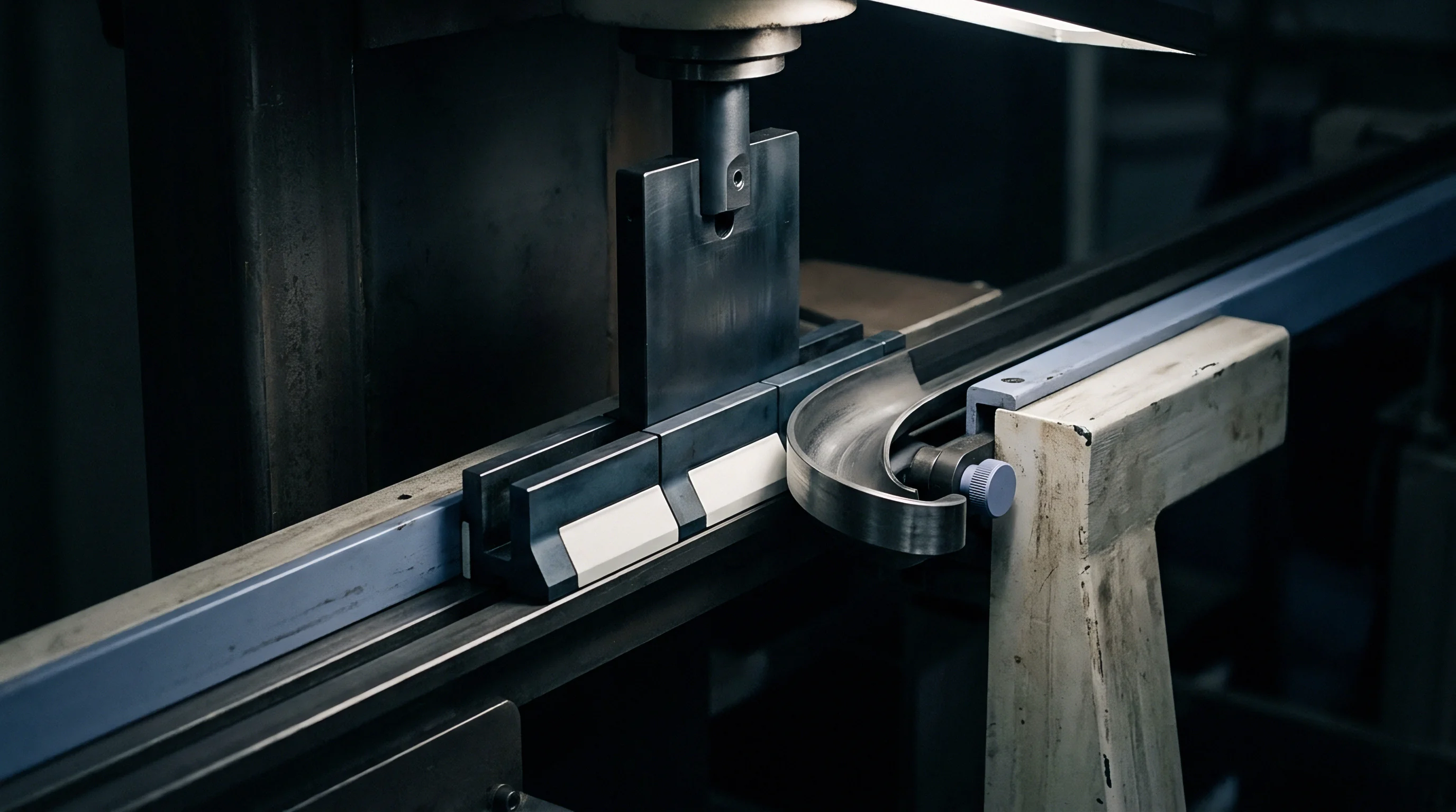
Chase
Clamping mechanisms secure heated dies against lateral displacement while accommodating continuous thermodynamic movement. The honeycomb bed provides an array of threaded or toggle apertures across its working area. Hardened steel toggles grip the beveled edges of the dies, pulling them down against the ground surface of the heater plate.
Each toggle exerts mechanical holding force through a bevel angle of 15 to 30 degrees, translating tightening torque into clamping pressure.
Fixing every edge of a large-format die rigidly locks the metal in place, converting thermal expansion into severe internal compressive stress. The die bows outward at its center, lifting off the platen surface by 0.05 to 0.15 millimeters. Platen drift exceeds allowable limits.
This upward distortion increases local impression pressure on central positions while starving perimeter positions of adequate dwell contact. Controlled positioning requires establishing a neutral thermal datum, usually the center of the die or the fixed gripper margin, allowing expansion to travel outward toward free edges.
Preheating stations off the press stabilize tooling assemblies before make-ready begins. Sliding a cold chase directly into a hot platen warps the carrier frame, introducing a bowing cycle that can take two hours of continuous heating to flatten. Experienced press crews mount dies on off-line preheating tables maintained at press operating temperature, tightening perimeter toggles only after the brass or copper plate reaches thermal saturation.
- Centerline datum pinning locks the spatial origin along the sheet travel axis, allowing transverse expansion toward both operator and drive sides without altering primary feeder timing.
- Spring-loaded toggle arrays maintain constant downward clamping force while sliding laterally in machined channels as the alloy plate expands under elevated bed temperatures.
- Step-etched expansion slots cut between adjacent carton positions isolate individual packaging impressions, interrupting continuous dimensional accumulation across the layout.
- Off-line thermal soak cycles bring complete die and chase assemblies to operating temperature before final micrometer calibration, locking running dimensions before press loading.
Digital measurement systems integrated into contemporary flatbed foil presses monitor chase position continuously. Optical sensors track fiducial marks on the die plate relative to the machine gripper bar. When temperature drops occur during stock replenishment or pallet changes, the press automation adjusts platen positioning to compensate for temporary die contraction.
Tooling expansion destroys carton register. Maintaining uniform thermal mass throughout the chase eliminates cold spots that otherwise cause localized registration failure across the sheet width.
Thermal expansion causes die displacement when toggles remain locked against moving metal boundaries.
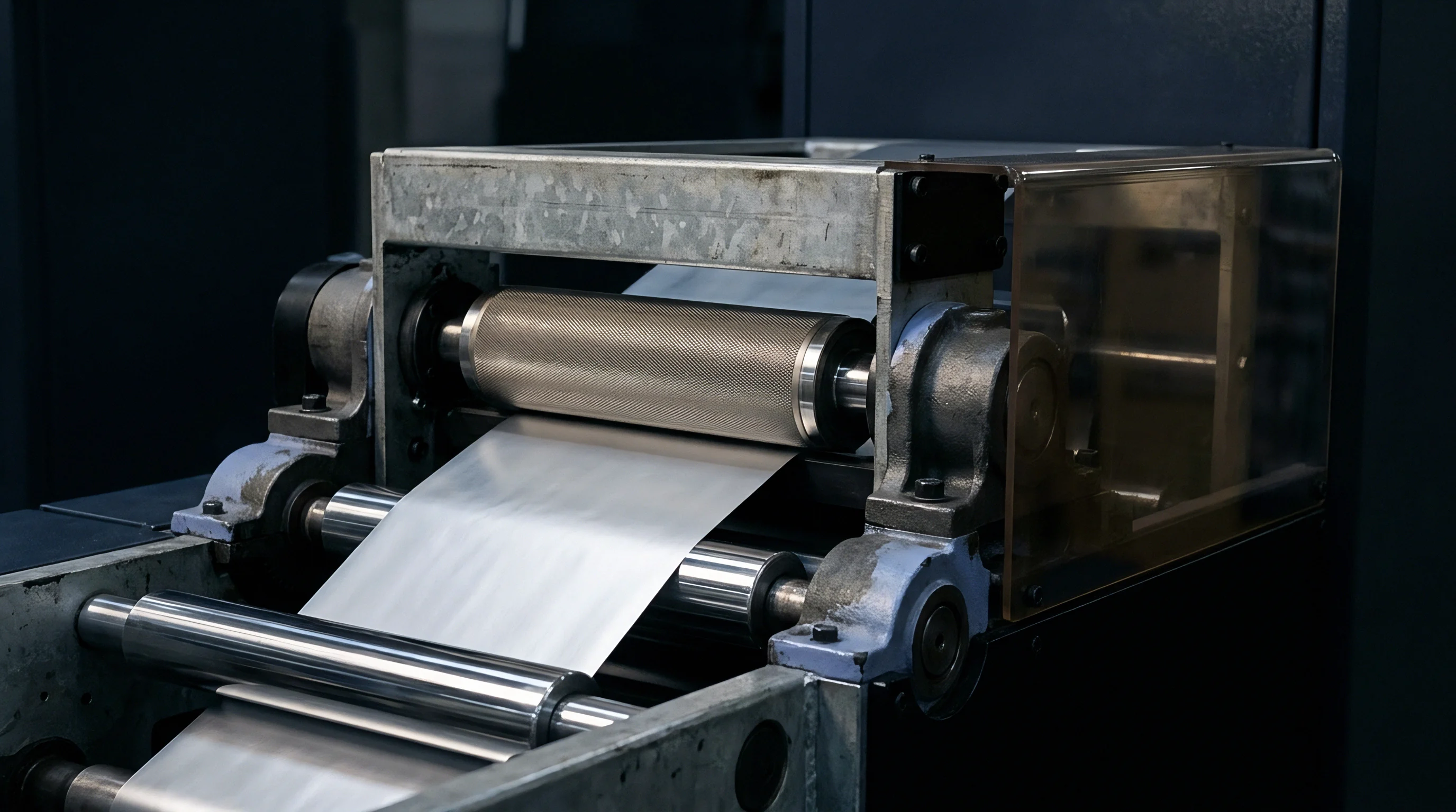
Creep
Counterforce tools establish the female cavity required to push cartonboard into the hot embossing die. Modern counterforces utilize milled phenolic paper laminates, cast glass-reinforced epoxy composites, or polyurethane polymers mounted on thin steel carrier sheets. While the male die remains thermally stable after reaching equilibrium, the counterforce undergoes aggressive cyclic compressive loading at elevated temperatures.
High-speed presses generate contact pressures from 20 to 60 megapascals across the raised embossing details during each platen close.
Conductive heat transfers through the paperboard into the counter material during each impression. Although paperboard functions as a poor thermal conductor, the surface skin of the matrix heats to 60 to 90 degrees Celsius across an extended run. When the temperature of an epoxy or phenolic counter approaches its glass transition point, the polymer matrix loses elastic modulus.
Viscoelastic creep accelerates under repeated impact, producing irreversible plastic deformation in high-pressure detail zones.
Nip pressure drives permanent counter thinning. The micro-structure of the matrix compresses permanently, widening the female groove and rounding crisp relief shoulders. This mechanical degradation diminishes debossing sharpness and allows the foil to bridge across carton edges, resulting in ragged borders and micro-cracking along deep crease lines.
The counterforce loses the geometric fidelity established during initial make-ready.
| Counterforce Material | Glass Transition Temperature (°C) | Compressive Modulus (GPa) | Creep Onset Pressure at 70°C (MPa) | Permanent Strain after 50,000 Cycles (%) |
|---|---|---|---|---|
| Phenolic Kraft Laminate (Pertinax) | 125 to 140 | 8.5 | 45 | 1.8 to 2.4 |
| G10 Woven Glass Epoxy | 135 to 155 | 18.0 | 65 | 0.6 to 0.9 |
| Cast Acrylic Photopolymer | 85 to 100 | 3.2 | 22 | 4.5 to 6.2 |
| Milled Brass Counterplate | N/A (Crystalline) | 105.0 | 180 | < 0.05 |
Phenolic kraft boards demonstrate anisotropic creep behavior linked directly to fiber orientation. Compressive deformation proceeds more rapidly perpendicular to the paper sheets comprising the laminate. Under heavy tonnage, resin-starved zones within the board experience micro-delamination, causing the counterforce to sink into the carrier plate.
Glass-reinforced epoxy counters resist this degradation mode by utilizing woven silane-treated glass fabrics that distribute localized compressive shear evenly across the base.
- Shoulder rounding blurs transition angles between flat foil areas and raised embossing relief, degrading microscopic image acuity across packaging typography.
- Groove shallowing reduces male die penetration into the matrix, thinning embossing height from an approved 120 microns down to 75 microns across long runs.
- Matrix delamination separates reinforcing fibers from the cured resin binder, creating soft pockets that absorb impression energy and cause spotty foil adhesion.
- Lateral ridge creep forces counter walls outward into open non-embossing zones, crushing delicate board flutes or cutting adjacent surface varnishes.
Polymer counters soften under sustained dwell. When running combinations of foil stamping and blind micro-embossing on solid bleached sulfate board, press speeds must remain steady. Interrupting the run leaves the counterforce resting in close proximity to the radiant heater plate.
Ambient air inside the open platen heats the matrix surface above its glass transition threshold. Restarting the press immediately subjects softened polymer details to full impact pressure, instantly flattening the delicate matrix channels.
Counters made from unreinforced photopolymers yield permanently when interface temperatures exceed eighty degrees Celsius under cyclic platen tonnages.
Does the counterforce matrix creep predictably across varying board calipers, or does moisture migration from fresh stock induce localized hydrothermal swelling that masks mechanical deformation?
Model
Predictive calculation of tooling distortion demands coupling thermodynamic thermal expansion equations with mechanical viscoelastic strain formulations. Linear expansion follows classical thermal mechanics. The change in length equals the original dimension multiplied by the alloy expansion coefficient and the operational temperature differential.
Predicting dynamic behavior on a high-speed converting press requires adjusting the static formula with a heat-loss attenuation factor that reflects machine velocity, stock caliper, and sheet dwell time.
Compensating for dynamic expansion requires applying scaling factors during pre-press computer numerical control engraving. The die file shrinks along both horizontal and vertical axes to ensure the tool reaches nominal design dimensions only when heated to full operational equilibrium. The compensation scale factor equals the inverse of one plus the product of the expansion coefficient and the net temperature rise.
Applying an incorrect scale produces dies that match film proofs perfectly at 20 degrees Celsius but drift out of register across the sheet at 140 degrees Celsius.
The following pre-press scaling protocol governs multi-up carton layouts before engraving tooling plates:
- Identify the core alloy composition, verifying the specific expansion coefficient against certified foundry melt certificates rather than relying on nominal alloy handbook values.
- Determine the pressroom baseline temperature and the target platen setpoint required for the specified foil release chemistry, establishing the operational thermal delta.
- Calculate individual machine direction and cross direction scaling factors, incorporating platen mechanical constraint coefficients derived from toggle positioning geometry.
- Apply the calculated reduction scale factor to the master vector geometry within the CAD engraving software, preserving center-point registration marks.
- Mill thermal relief channels between active image clusters on dies wider than 400 millimeters to segment continuous expansion spans into discrete, manageable zones.
Predicting matrix creep requires a modified Findley power-law formulation where creep strain accumulates as a function of cycle count, contact stress, and interface temperature. The total strain combines instantaneous elastic deformation with time-dependent viscoelastic creep. Secondary steady-state creep dominates during normal production running, while tertiary creep accelerates rapidly if interface temperatures exceed the matrix glass transition value.
Die temperature stabilizes at production speed.
| Run Progression (Sheets) | Bed Temperature (°C) | Uncompensated Brass Drift (mm) | Compensated Brass Error (mm) | Phenolic Counter Creep (μm) | G10 Epoxy Counter Creep (μm) |
|---|---|---|---|---|---|
| 1,000 (Make-Ready) | 110 | +1.85 | -0.42 | 2 | 1 |
| 5,000 (Thermal Equilibrium) | 130 | +2.29 | +0.02 | 8 | 3 |
| 25,000 (Mid-Run) | 130 | +2.29 | +0.03 | 24 | 7 |
| 50,000 (Shift Change) | 125 | +2.18 | -0.08 | 38 | 11 |
| 80,000 (Run Completion) | 130 | +2.30 | +0.03 | 52 | 14 |
Take an operational scenario involving a 1020-millimeter wide layout on 350 grams per square meter coated folding boxboard running on a modern flatbed platen press. The target image requires tight foil stamping inside an offset-printed boundary line with an allowable registration tolerance of plus or minus 0.15 millimeters across all sheet positions. Operating temperature is 135 degrees Celsius with a baseline room temperature of 22 degrees Celsius, yielding an operational delta of 113 Kelvin.
An uncompensated C36000 brass tool expands 2.36 millimeters across the full 1020-millimeter chase span under these conditions. The outermost carton positions on the drive and operator sides displace 1.18 millimeters away from the center mark, exceeding the allowable tolerance band by nearly eight times. Preheating prevents mid-run drift.
When the engraver applies a 0.99770 scaling factor during die milling, the cold tool measures 1017.65 millimeters. Upon reaching 135 degrees Celsius on press, the tool expands to exactly 1020.01 millimeters, holding every packaging position within 0.02 millimeters of true position across the entire sheet layout.
Tooling purchase contracts specifying DIN ISO 2768-m tolerances apply exclusively to tooling dimensions measured at twenty degrees Celsius and require explicit addenda to govern thermal expansion compensation factors.
Spoilage
Dimensional errors originating from unpredicted thermal expansion and matrix creep generate substantial commercial losses during packaging production. When dynamic expansion moves stamping dies beyond printing boundaries, cartonboard stock is immediately downgraded to waste. The cost of running uncompensated tooling multiplies across high-speed machinery capable of converting two sheets every second.
Setup waste climbs rapidly.
Foil stamping adds a distinct converting pass with fixed machine setup costs and running waste allowances. In folding carton production, an added stamping pass carries an average setup waste of 300 to 500 sheets during initial registration, with running spoilage typically priced at 1.5 to 2.5 percent of the total job volume. When tooling expands unpredictably, make-ready lengthens as press operators repeatedly loosen toggles, reposition individual die sections, and re-shim impression zones.
A setup extending from two hours to six hours consumes thousands of euros in direct press time while burning through expensive multi-layer foil rolls.
Matrix creep introduces a more insidious cost pattern because failures manifest downstream from the stamping line. Counterforces that degrade gradually during a run produce acceptable sheets during first-off approval but generate shallow, incomplete embossing on later pallets. Pallets delivered to automated high-speed carton filling lines fail during packaging erection.
Shallow crease scoring or collapsed debossed panels jam carton magazines, triggering formal packaging rejections and warranty claims from the brand owner.
Tooling replacement mechanics influence run profitability. Milled brass dies carry substantial initial capital costs, often reaching three to five times the price of chemically etched magnesium plates. Brass delivers repeatable dimensional behavior, wear resistance exceeding one million impressions, and high thermal stability.
Specifying cheaper magnesium dies on long-run high-speed packaging runs creates false economy: magnesium creeps mechanically under high platen impact pressure, expands excessively under heat, and requires premature replacement mid-run. The financial loss from two hours of unscheduled press downtime exceeds the initial purchase savings achieved by choosing low-cost die alloys.
Environmental packaging mandates and extended producer responsibility fees penalize finishing scrap heavily. Defective stamped cartons cannot bypass waste sorting streams, and hot stamping foil residues complicate single-stream fiber repulpability evaluations when defective runs are pulped. Minimizing production spoilage through rigorous thermodynamic tool modeling protects net margins, preserves machine run schedules, and satisfies waste-reduction targets demanded by international packaging compliance standards.
Stable production requires balancing tool temperatures before locking impression registers.