Matrix Channel Width Selection Criteria for Calibrated High Speed Automatic Creasing
Calibrated matrix channel width relies on board caliper, rule thickness, and fiber shear mechanics to prevent liner cracking and gluer jams.


Groove
Operating at nine thousand sheets per hour, automatic creasing platens form folding cartons by subjecting paperboard to localized mechanical strain. As the male creasing rule enters the female channel of a matrix strip, it creates a double-shear deformation zone, drawing the top liner down while internal plies delaminate along microscopic shear planes. Sizing the channel correctly isolates this deformation to internal layers, protecting printed coatings and external surfaces from fracture.
An incorrect channel geometry upsets this balance immediately. A narrow channel pinches the board and drives tensile stress past the top liner’s yield point, cracking clay coatings and splitting laminated films. If the channel is too wide, the rule fails to compress the sheet internally, producing a shallow, unstructured bead that buckles during downstream folding.
High-speed folder-gluers cannot handle erratic crease profiles, which leads directly to sensor trips, jam-ups, and scrap surges.
Kinematics of Male Rule Penetration
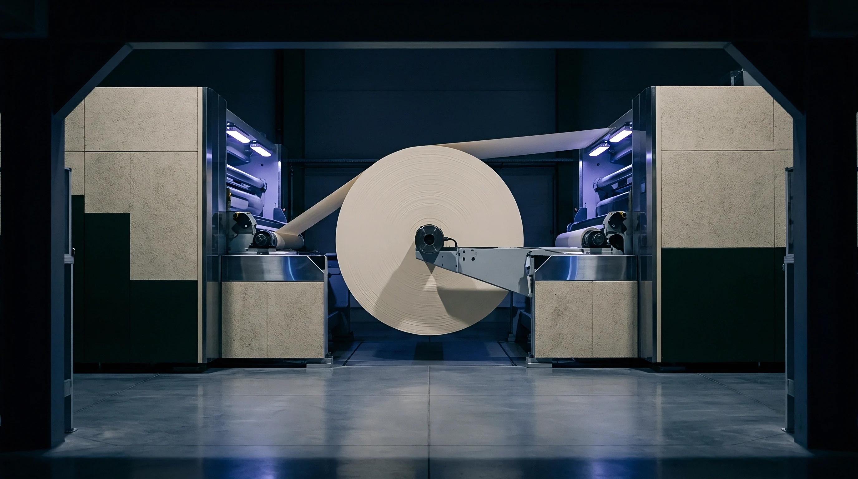
On modern flatbed die-cutters, the male steel rule strikes the paperboard at speeds above two meters per second. During penetration, the board undergoes vertical compression while stretching laterally across the matrix channel shoulders. As the rule drives the bottom liner down against the counter plate, displaced fibers move outward against the channel walls to form an internal bead.
Shearing must overcome the board’s internal bond strength without surpassing the tensile limit of the outer liner. This mechanical strain profile is determined by the side clearance between the rule face and the vertical matrix wall, which governs the bending radius of the board entering the channel.
Too little clearance pinches the board against the matrix shoulder, shifting bending strain into through-caliper shearing that cuts surface fibers and exposes white core fractures on printed areas. Proper clearance allows plies to slide over each other cleanly, providing the delamination needed for low-torque folding.

Mathematical Sizing Baseline Formulations
Establishing matrix channel width relies on three core variables: male rule thickness, paperboard caliper, and an empirical factor accounting for substrate density and fiber elongation.
The standardized formula for calculating matrix channel width on solid bleached sulphate board and folding boxboard is expressed as:
Channel Width = Rule Thickness + (1.5 x Board Caliper)
Dense recycled grades like coated recycled board and white lined chipboard resist internal delamination due to ply stiffness, requiring a wider deformation zone:
Channel Width = Rule Thickness + (1.7 x Board Caliper)
Channel depth typically matches nominal sheet caliper to allow sufficient bead formation without crushing. On high-density solid boards, operators often reduce depth by ten percent to increase compression and set the delaminated plies.
A channel width calculation multiplier of 1.5 times caliper applied to 400 micrometer folding boxboard produces a 1.31 millimeter channel width that prevents top liner rupture at production speeds of 10,000 sheets per hour.
| Board Caliper (mm) | Board Grade | Creasing Rule Thickness (Pt / mm) | Width Multiplier Factor | Calculated Channel Width (mm) | Recommended Channel Depth (mm) |
|---|---|---|---|---|---|
| 0.35 (350 µm) | Solid Bleached Board (SBB) | 2 Pt (0.71 mm) | 1.5 | 1.24 | 0.35 |
| 0.40 (400 µm) | Folding Boxboard (FBB) | 2 Pt (0.71 mm) | 1.5 | 1.31 | 0.40 |
| 0.50 (500 µm) | Folding Boxboard (FBB) | 2 Pt (0.71 mm) | 1.6 | 1.51 | 0.50 |
| 0.60 (600 µm) | Coated Recycled Board (CRB) | 3 Pt (1.05 mm) | 1.7 | 2.07 | 0.60 |
| 0.80 (800 µm) | Coated Recycled Board (CRB) | 4 Pt (1.42 mm) | 1.8 | 2.86 | 0.80 |
Deviations from these baseline formulas cause rapid mechanical defects. High-volume converting lines monitor score profiles continuously to catch sizing errors before jobs move into finishing.
- Liner surface rupture occurs when an excessively narrow channel forces the male creasing rule to cut top fibers instead of inducing clean internal shear delamination.
- Inadequate bead formation develops when an overly wide matrix channel allows paperboard to bow downward without sufficient localized compression along the crease axis.
- Internal ply crushing happens when channel depth is insufficient, compressing solid board structures into rigid, unbendable solid masses.
- Crease line drift arises when adhesive matrix tape yields laterally under high-speed dynamic shear impacts during long converter shifts.
Running channels narrower than the calculated threshold shears fibers rather than delaminating them, generating excess dust, high liner rupture rates, and rejected lots at the filling plant.

Substrate
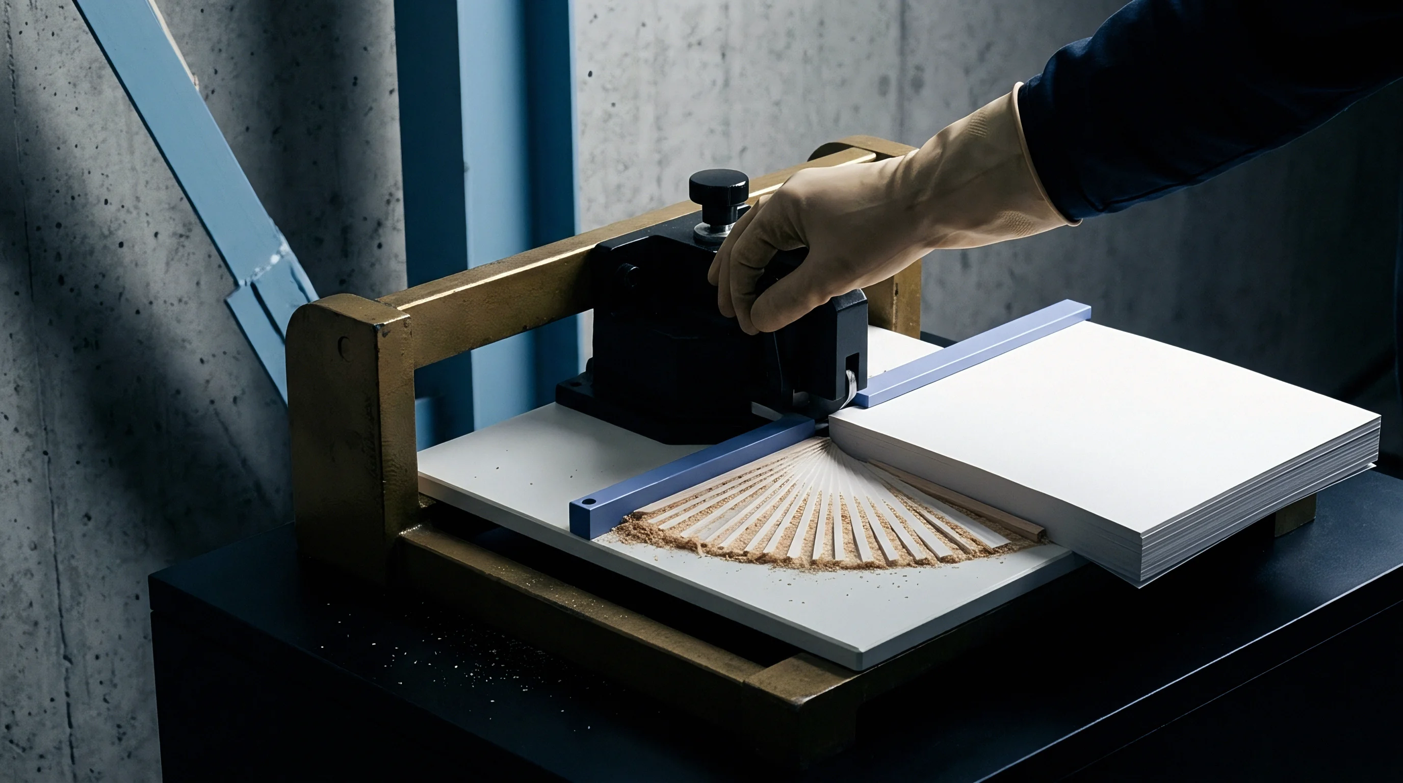
Fiber structure dictates how paperboard layers separate under counter-die penetration. Virgin bleached hardwood fibers form clean, uniform shear planes, whereas multi-ply recycled sheets contain short, degraded fibers that resist internal sliding. Fiber alignment, moisture content, and coating elasticity all alter the effective channel width required for a durable folding hinge.
Grain direction remains decisive during high-speed converting. Creases running parallel to the machine direction follow the orientation of the cellulose fibers; because these fibers part easily, narrower channels are sufficient to induce delamination. Cross-grain creases force the rule to bend across fiber bundles, requiring wider matrix channels and slightly lower rule heights to prevent top liner cracking during folding.
Fiber Layer Delamination and Scott Bond Values
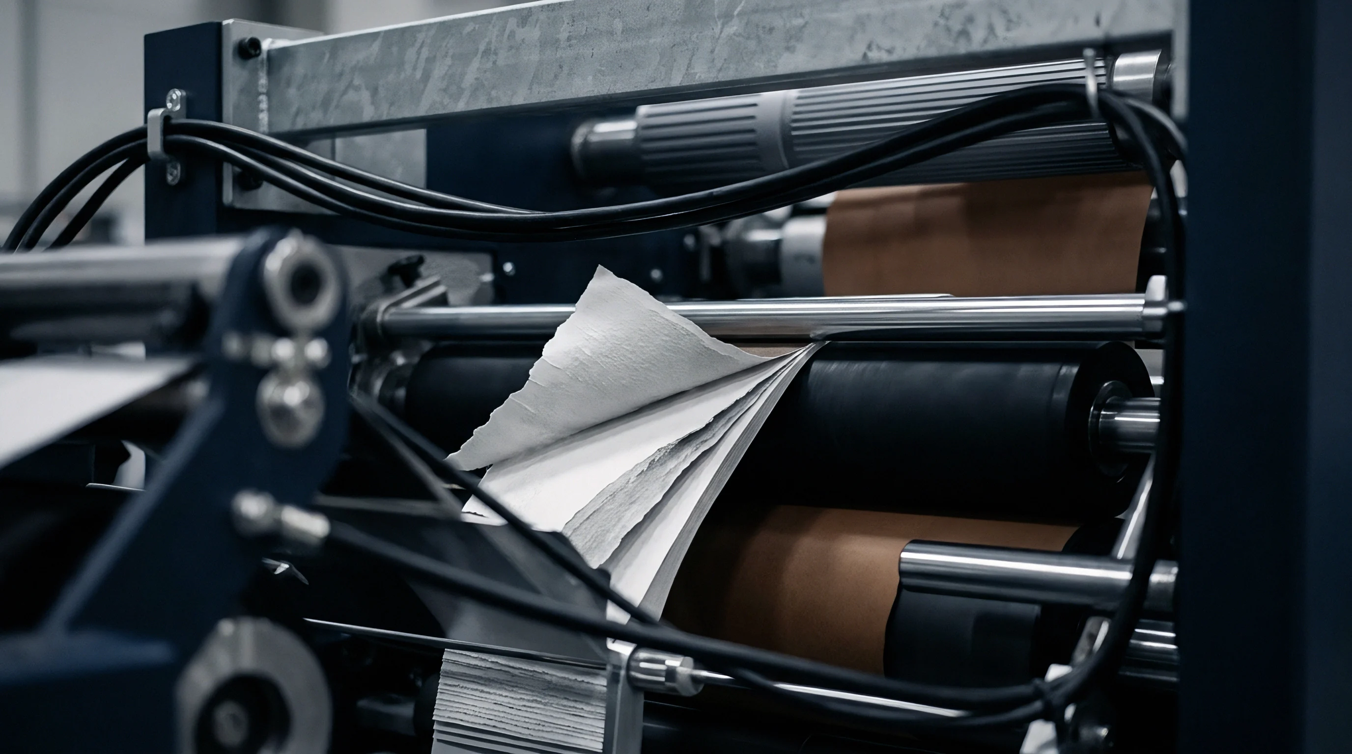
Internal bond strength measured under ISO 16260 defines the energy required to separate paper layers into continuous internal hinges. Boards with Scott Bond values above 200 Joules per square meter require higher mechanical force to initiate ply separation. If the matrix channel is too narrow on these high-strength grades, the required force exceeds the tensile threshold of the coated liner, causing immediate surface cracking.
Low Scott Bond structures, typical of high-yield mechanical pulp layers in folding boxboard, delaminate under lower loads. These boards tolerate tighter channel width multipliers without surface splitting, yielding crisp carton corners. When moisture content falls below five percent, fiber elasticity drops sharply, causing outer liner fractures unless the press operator widens the channel.
Matrix Material Selection Matrix across Paperboard Grades
Choosing an appropriate counter-die material ensures consistent channel geometry across extended runs. Under repeated impact, dimensional stability dictates how long a matrix channel holds its calibrated width before shoulder breakdown alters crease shape.
Recycled paperboard grades with lower internal shear strength demand wider matrix channel geometries than virgin fiber boards of identical caliper.
- Pressboard channel strips offer economic make-ready for short production runs below fifty thousand sheets but suffer rapid shoulder wear under high platen impact velocities.
- Phenolic resin counter plates provide excellent dimensional stability for medium to long runs, maintaining precise channel walls across hundreds of thousands of impressions.
- Milled steel counter plates deliver absolute channel tolerance precision for high-volume automated runs exceeding one million folding cartons.
- Synthetic resin matrices feature flexible locator strips that accelerate job setup while maintaining uniform channel width across variable humidity environments.
Flexible polyethylene and metalized polyester film laminates show distinctive elasticity under creasing strain. The films stretch across the channel, absorbing initial impact forces before transferring tension into the underlying board. The channel width multiplier for film-laminated substrates increases by 0.1 to 0.2 over standard formulas to prevent film lifting, bubbling, or delamination along the score edge.
Density variations across paperboard mills make baseline trial runs necessary, with operators keeping matrix widths wider on recycled board lots to compensate for short fiber brittleness.


Tolerance
Dynamic platen deflection during peak running speeds alters rule penetration depth. At eight thousand sheets per hour, flatbed presses exert hundreds of metric tons across the die chase. Microscopic flexing of the press bed and top platen creates depth variations between the center and perimeter of the die, directly affecting matrix engagement.
Adhesive backing stability on self-adhesive matrix strips presents an operational variable on high-speed lines. Lateral forces generated during each penetration stroke press outward against the matrix channel shoulders. Thermal softening of adhesives under elevated pressroom temperatures permits shoulder creep, gradually widening the channel over long production runs.

High Speed Platen Dynamics and Wear Mechanics
Running at eleven thousand impressions per hour subjects pressboard shoulders to severe repetitive impacts. As the shoulders deform outward, the sharp vertical wall transforms into a rounded ramp. This loss of edge definition decreases localized compression on the board, producing a broad, flattened bead.
Platen parallelism calibration ensures uniform rule penetration across the entire sheet layout. Even a three-hundredth of a millimeter variance across the bed alters the ratio between outer liner stretch and internal ply shear. Die-makers install calibrated steel shims beneath cutting and creasing rules to equalize penetration forces across large format platens.
| Matrix Material | Platen Speed (sheets/hr) | Initial Channel Width (mm) | Final Channel Width (mm) | Width Expansion (%) | Crease Stiffness Drift (%) |
|---|---|---|---|---|---|
| Pressboard Strip | 7,000 | 1.40 | 1.52 | 8.57 | +18.4 |
| Pressboard Strip | 9,500 | 1.40 | 1.61 | 15.00 | +32.1 |
| Phenolic Resin Strip | 9,500 | 1.40 | 1.43 | 2.14 | +4.2 |
| Phenolic Resin Strip | 11,500 | 1.40 | 1.45 | 3.57 | +6.8 |
| Milled Steel Plate | 11,500 | 1.40 | 1.40 | 0.00 | 0.0 |

Counter Plate Material Properties
Phenolic resin compounds, milled steel plates, and pressboard matrix strips exhibit vastly different dimensional stability profiles across long production runs. Milled steel plates maintain zero wall deformation across millions of cycles, fixing channel geometry perfectly throughout the life of a cutting die. Phenolic counter plates yield slight elastic deformation under high impact, providing a balance between long tooling life and forgiving make-ready parameters.
Dynamic vibration during continuous automatic platen operation causes pressboard matrix channels to widen progressively over extended impression cycles.
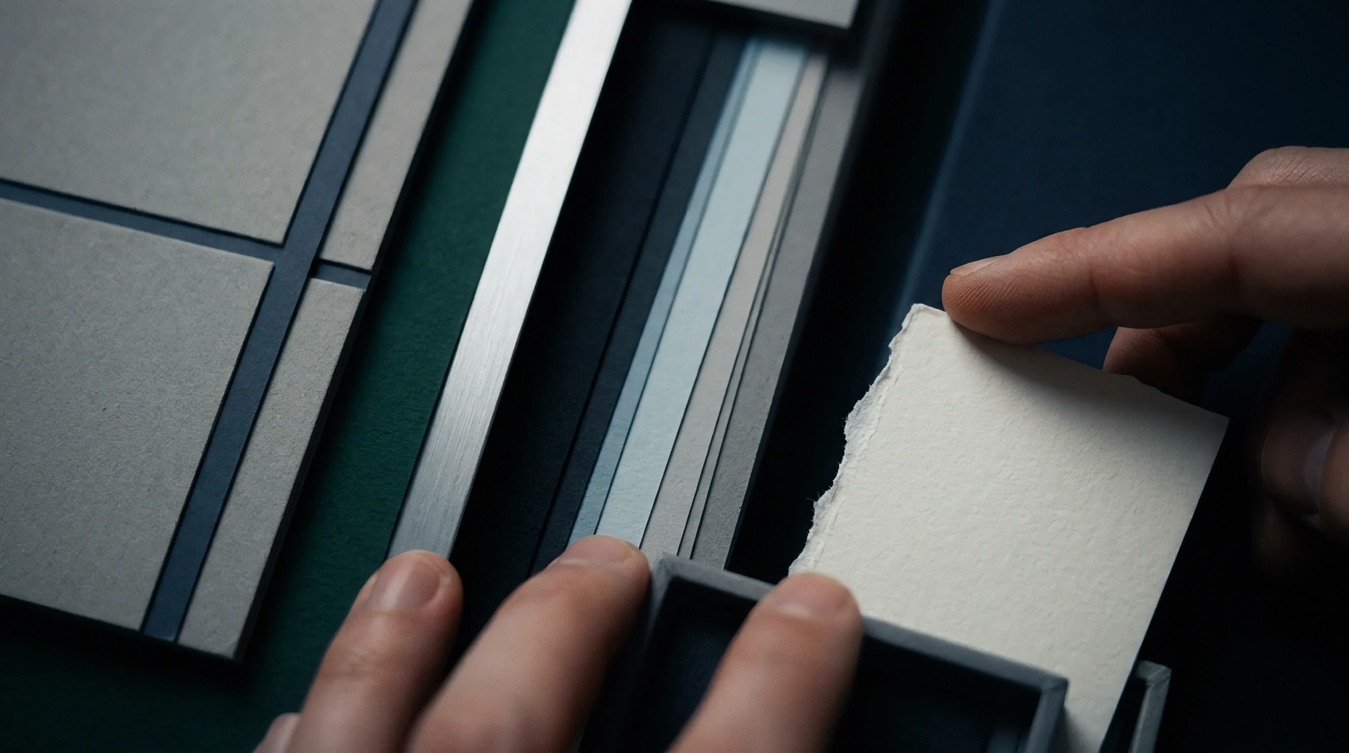
Matrix shoulder chamfer angles determine how smoothly paperboard enters the recess during impact. A vertical ninety-degree wall imposes sharp shear points on the bottom liner, raising the risk of tearing. A pre-chamfered shoulder angle of thirty to forty-five degrees guides the board gradually into the channel, moderating peak force spikes during penetration.
While platen dampening systems reduce dynamic micro-deflection, converting floors consistently observe channel shoulder compression and score drift after six hours of continuous high-velocity operation.

Bending
Quality control laboratories measure the residual torque of folded scores using standardized mechanical testing rigs. ISO 2493 and DIN 53121 standards establish protocols for evaluating crease stiffness by measuring the force needed to bend a creased paperboard sample through a ninety-degree angle at a fixed distance from the score line. The crease stiffness ratio compares the bending force of a creased sample directly against the bending force of an uncreased board sample from the same production batch.
An optimized crease yields a bending stiffness ratio between thirty and forty-five percent of the uncreased board strength. Ratios above fifty percent indicate inadequate internal delamination, which forces automatic packaging machine arms to exert excessive force during carton erection. High resistance causes carton blank misfeeds, panel bowing, and glue seam pop-offs on high-speed cartoning equipment.
Ratios below twenty-five percent signal severe fiber damage, leaving carton folds weak and unstable during stacking.

Which Matrix Profile Prevents Coated Board Cracking?
Polymer matrix constructions with rounded shoulder radii reduce stress concentration points along outer liner coatings during rapid sheet folding. Smooth shoulder transitions allow brittle clay coatings and soft-touch aqueous varnishes to stretch gradually over the crease bead without micro-fracturing along the outer fold apex.
Crease stiffness testing across varying matrix widths confirms the inverse relationship between channel clearance and bending torque. Narrow channels increase localized compression, lowering bending resistance at the expense of higher top liner cracking risks. Sizing toward the wider end of the calculated tolerance spectrum reduces cracking while slightly increasing bending resistance.
Consider a 450 micrometer (0.45 mm) solid bleached board creased with a 2 Pt (0.71 mm) steel rule. Applying the baseline formula yields a calculated channel width of 1.385 millimeters (0.71 mm + 1.5 x 0.45 mm). Operating at nine thousand sheets per hour, initial bench testing shows top liner clay cracking along cross-grain score lines.
Widening the matrix channel to 1.485 millimeters (using a 1.7 multiplier factor) drops top liner tension below the clay fracture limit. Bench analysis confirms the creased bending stiffness ratio shifts from 32 percent to 38 percent, remaining safely within the 45 percent maximum threshold allowed by high-speed cartoning line specifications.

Calibrated Drawdown Test Protocol
Establishing optimal channel geometry requires systematic trial pressings under controlled platen impression pressure. Bench-scale verification before commencing full production runs prevents costly rework and stock waste on high-volume orders.
- Mount the designated steel creasing rule in the platen die chase, confirming vertical height alignment with a dial indicator.
- Apply the target matrix channel strip to the cutting plate using calibrated locator bridges attached to the creasing rule.
- Cycle the platen press slowly to transfer and bond the self-adhesive matrix tape securely to the counter plate.
- Pass three test sheets of production paperboard through the press at low speed to establish baseline impression depth.
- Ramp press speed to eight thousand sheets per hour and collect five consecutive samples for crease stiffness measurement.
- Evaluate crease bending resistance on an ISO 2493 calibrated tester, adjusting channel width if bending torque exceeds forty percent of uncreased board torque.
Whether ultra-thin synthetic counter plates can maintain uniform crease stiffness ratios across temperature fluctuations during multi-million impression runs remains an open question among high-speed finishing operations.

Outlay
Inaccurate matrix channel dimensions generate immediate financial losses through ruined paperboard stock and line downtime. Scrap rates on high-speed flatbed die-cutters escalate within minutes when improper matrix sizing produces cracked scores or incomplete creasing beads. At production speeds exceeding ten thousand sheets per hour, a press running non-compliant carton blanks generates thousands of sheets of scrap before quality control operators complete visual inspections.
Tooling choices directly balance initial make-ready expenditure against operational efficiency over the run. Standard pressboard matrix channels carry low initial material costs, making them appealing for short-run jobs. However, their rapid mechanical wear rate requires frequent replacement during long production runs.
Every matrix replacement cycle requires press shutdown, channel stripping, plate cleaning, and re-alignment, adding significant downtime cost to the job ledger.

Commercial Economics of Sizing Errors
Miscalculated matrix channel widths increase make-ready delays while operators attempt manual chamfer adjustments or replace misaligned counter strips. Modern high-speed converted folding carton operations price press downtime at hundreds of dollars per hour, far exceeding the unit cost of premium phenolic counter plates or precision milled steel counter dies.
Downstream economic consequences emerge when non-compliant creased carton blanks reach automated filling facilities. Packing lines operating at six hundred cartons per minute require strict dimensional tolerance compliance on every crease line. Cartons with excessive crease stiffness fail to square up inside cartoner pockets, triggering automatic machine stops.
The cost of line stoppages at a customer packaging plant frequently results in formal quality rejections, full batch returns, and financial indemnity claims against the converter.
Compliance with DIN 53121 score bending stiffness mandates a maximum crease-to-uncrased bending ratio of 0.45 to prevent high-speed automatic gluing line jams.
Contractual Specification and Tolerance Standards
Formal purchasing agreements for high-speed folding cartons stipulate rigid limits on maximum allowed crease stiffness and visual liner cracking. Packaging buyers mandate compliance with recognized international test standards to ensure predictable performance across automated packaging systems.
Quality assurance addendums specify statistical sampling protocols based on ISO 2859-1 criteria. These agreements define acceptable quality limit thresholds for visual score defects, board delamination errors, and fold stiffness variations.
Standard delivery contracts referencing ISO 2493 bending resistance compliance require supplier compensation whenever mean crease stiffness exceeds forty-five percent of uncreased board stiffness, forcing carton converters to rework non-compliant die tooling at their own expense.