Anisotropic Fiber Bending Stiffness Tradeoffs in High Speed Packaging Die Layout Imposition Engineering
Imposition layouts that nest cartons across grain directions reduce parent sheet trim but induce bimodal stiffness variance and high-speed feeder jams.


Grain
As the paper web travels over the forming wire, wood fibers align mostly in the running direction. This gives folding boxboard (FBB), solid bleached sulfate (SBS), and coated recycled board (CRB) clear orthotropic behavior. Depending on headbox jet-to-wire speed ratios, furnish refining, and wet-end fiber dynamics, machine direction (MD) elastic modulus runs 1.6 to 3.2 times higher than cross direction (CD) modulus.
In structural carton design, that asymmetry dictates the bending stiffness measured under ISO 2493-1 (two-point method at 15 degrees) or TAPPI T 489 (Taber-type tester at 15 degrees). Bending stiffness ~ the product of elastic modulus and area moment of inertia per unit width ~ determines blank deflection under load, panel resistance to internal pressure, and crease behavior during high-speed erection.
Imposition layout trades sheet yield against crease orientation relative to the grain. Converters balance the scrap savings of interlocking dies against layouts where body creases run strictly parallel to the machine direction. Rotating carton blanks in alternating 90-degree nests can save 3.5 percent yield on a standard 1020 mm by 1420 mm parent sheet, but half the batch leaves the die with its body panels aligned along the weaker CD axis.
That produces two mechanically distinct carton populations in a single run, creating immediate instability on lines operating between 400 and 900 cartons per minute.
Under ISO 2493-1 conditioning at 23 degrees Celsius and 50 percent relative humidity, a 350 g/m² virgin fiber folding boxboard exhibits an MD bending resistance of 285 mN and a CD bending resistance of 125 mN.
That anisotropy forms right at the headbox slice. As dilute fiber slurry discharges onto the fourdrinier wire or twin-wire former at 0.5 to 1.2 percent consistency, hydrodynamic shear aligns suspended fibers with the machine direction. Wet pressing and unrestrained cross-web shrinkage during cylinder drying accentuate the gap: the sheet develops CD micro-creping while longitudinal web tension keeps the MD taut.
The finished board displays higher tensile stiffness, tensile strength, and flexural rigidity in the machine direction, set against lower dimensional stability and higher hygroexpansion across the web. For converters evaluating board lots, the MD to CD stiffness ratio acts as a direct signature of the paper machine’s forming geometry.

Mechanical Properties across Standard Packaging Grades
Furnish composition largely controls these stiffness profiles. Solid bleached sulfate, manufactured from virgin chemical hardwood and softwood pulps, maintains uniform density with MD to CD stiffness ratios between 1.8 and 2.2. Folding boxboard sandwiches a thermo-mechanical pulp (TMP) or groundwood center ply between chemical pulp outer layers, creating a high-bulk I-beam structure that maximizes stiffness per unit basis weight and pushes MD to CD ratios up to 2.2 to 2.8.
Coated recycled board uses shortened recycled fibers with high mineral filler content, yielding lower specific modulus and wider stiffness ratio variations between 1.5 and 2.0.
| Substrate Classification | Basis Weight (g/m²) | Caliper (µm) | MD Bending Stiffness (mN·m) | CD Bending Stiffness (mN·m) | Anisotropy Ratio (MD/CD) |
|---|---|---|---|---|---|
| Solid Bleached Sulfate (SBS) | 300 | 380 | 19.5 | 9.8 | 1.99 |
| Folding Boxboard (FBB) | 300 | 505 | 28.2 | 11.4 | 2.47 |
| Coated Recycled Board (CRB) | 350 | 460 | 16.8 | 9.6 | 1.75 |
| Unbleached Kraft Board (CUK) | 330 | 440 | 26.4 | 12.1 | 2.18 |
| Recycled White Lined Chipboard (WLC) | 400 | 520 | 21.0 | 11.1 | 1.89 |
Evaluating panel deflection requires classic plate bending theory adapted for orthotropic materials. Under a distributed out-of-plane load, flexural rigidity terms D11 and D22 govern curvature along the principal material axes. Flexural rigidity per unit width is defined as:
D = (E · h³) / (12 · (1 – ν_MD · ν_CD))
where E is the directional elastic modulus, h is caliper, and ν is Poisson’s ratio. Because stiffness scales with the cube of caliper, even subtle shifts in sheet density or calendering pressure significantly impact flexural performance across both web directions. When parent reel caliper drifts across the deckle, downstream converting lines see immediate variation in opening forces and panel rigidity.
Increasing basis weight is often proposed to compensate for cross-grain impositions, on the premise that a higher grammage grade bridges the structural deficit when carton panels run perpendicular to grain through high-speed erecting machines.

Forme
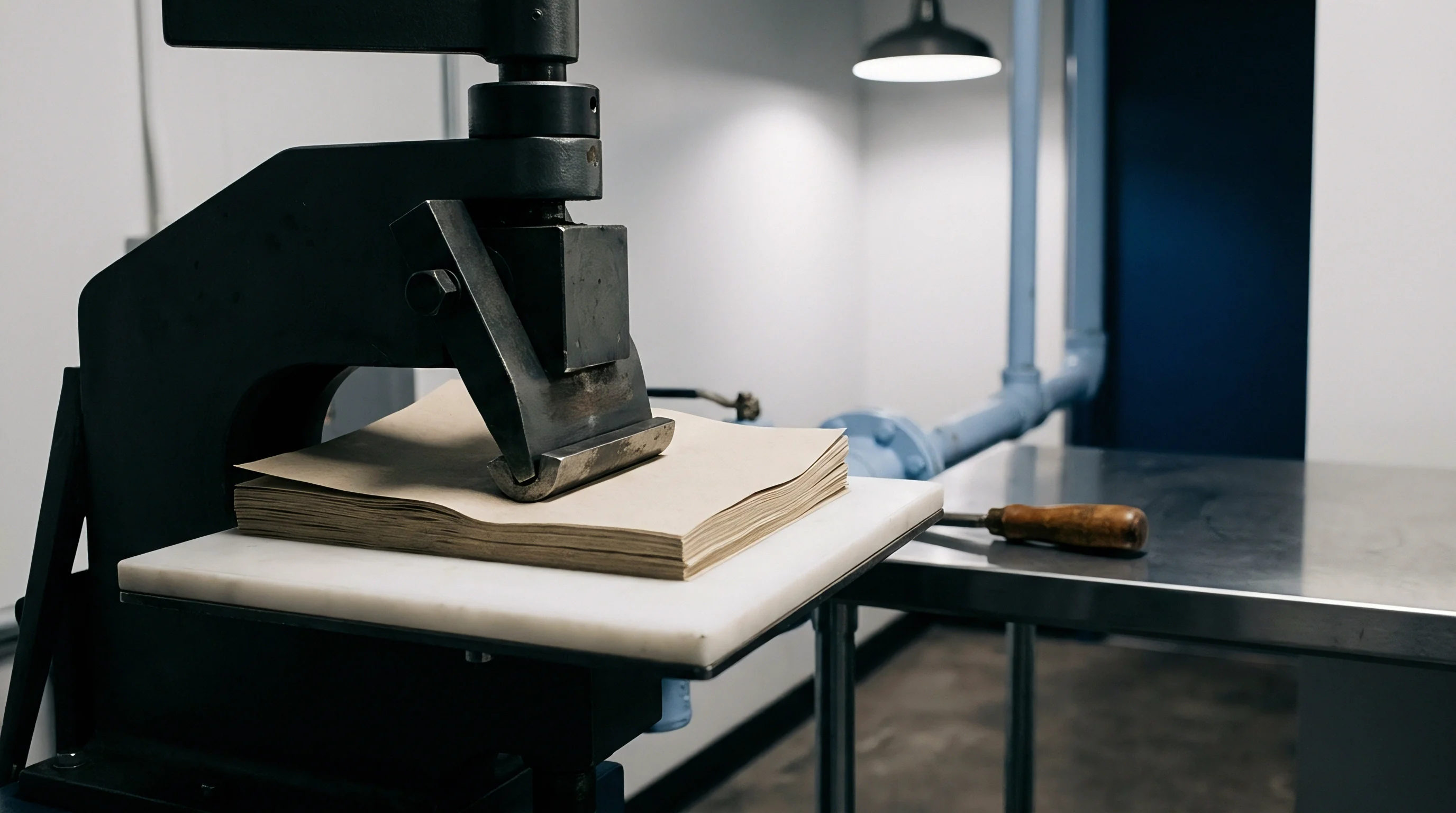
Flatbed and rotary cutting formes translate CAD layouts into physical tooling with steel cutting rules, creasing rules, stripping fingers, and ejection rubber. How blanks nest within the die chase fixes the orientation of every crease, cut, and score line relative to the sheet’s mill-cut grain. In straight impositions, all cartons share one orientation, running main longitudinal scores strictly parallel or perpendicular to the sheet edge.
Interlocking or combination layouts arrange blanks head-to-foot, interlock closure flaps, or rotate cartons in 90-degree patterns to trim skeleton waste, close knife-to-knife gaps, and reduce board tonnage per million cartons converted.
Material saved through interlocking layouts can create bottlenecks on packaging lines. In a standard reverse-tuck carton measuring 80 mm wide, 40 mm deep, and 150 mm high, aligning carton height with the MD keeps all four body creases parallel to the grain, yielding clean 90-degree folds under low resistance. Closure flaps fold across the grain, drawing on higher MD stiffness to resist tuck-in buckling.
Rotating half the blanks 90 degrees to save sheet waste flips those axes, leaving half the run with body creases running cross-grain and closure flaps parallel to it.
The structural impact appears clearly under the load of a cartoner’s feeding mechanism. Vacuum pickers pull the blank from the magazine, accelerate it along a circular or planetary path, and pull it against a stationary sword or reciprocating lug to erect the sleeve. If main face panels lack sufficient flexural stiffness across the span between suction cups and panel edges, the blank bows rather than breaking cleanly along score lines.
That bowing alters the leading edge trajectory, causing it to miss transport chain pockets and trip line stops.
Imposition Geometry and Mechanical Stress Vectors
Cutting rule orientation changes stress patterns during the stroke. Cutting across the grain pulls longitudinal fiber bundles in tension until they shear, leaving clean edges with minimal fiber tear. Cutting parallel to the grain wedges the rule between fibers along the middle lamella, inducing micro-delamination at the cut edge that lowers edge compression strength.
Creasing works in reverse: pressing a rounded steel rule into a counter-channel delaminates internal plies under controlled shear to create an internal hinge. This delamination works best when the rule aligns with fiber grain, allowing internal plies to slip into a reverse bead without rupturing surface liners.
| Imposition Parameter | Straight Grain Imposition | Alternating Nested Imposition (90°) | Interlocking Flap Imposition (0°/180°) |
|---|---|---|---|
| Sheet Area Utilization (%) | 84.2 – 88.5 | 91.0 – 95.8 | 89.0 – 93.4 |
| Carton Performance Variance | Uniform batch performance | Bimodal stiffness distribution | Uniform batch performance |
| Body Crease Grain Alignment | 100% Parallel to MD | 50% Parallel / 50% Perpendicular | 100% Parallel to MD |
| Cartoner Speed Capability | Maximum rated line speed | Derated by 15% to 35% | Maximum rated line speed |
| Die Tooling Complexity | Standard knife configuration | Complex shared-knife geometries | Moderate interlocking rules |
| Offcut Skeleton Stripping | Standard dynamic stripping | Narrow bridges, prone to jamming | Reliable pin stripping |
Shared-knife sections in nested dies demand tight tooling tolerances. When two blanks share a single cutting rule, impression forces support the rule evenly on both sides. In layouts with separate 3 mm to 5 mm waste strips, rules deflect asymmetrically if ejection rubber is unevenly distributed.
That deflection can introduce up to 2 degrees of bevel into the cut edge, throwing off carton squareness and skewing flap alignment during gluing.
Ejection rubber profiles are selected based on the local grain direction of surrounding panels. Closed-cell microcellular polyurethane rubbers rated at 45 to 65 Shore A hardness sit along cross-grain rules to counter the elastic recovery of longitudinal fibers. Along rules running parallel to grain, softer open-cell rubbers prevent surface marking and core crush that would degrade edge crush test (ECT) values on finished cartons.
Disregarding grain direction during imposition routinely leads to carton jams, erratic flap closing angles, and unrecoverable downtime across packaging lines.

Feeder
Automated packaging lines depend on precise feeder mechanisms to pull blanks from magazines and present opened sleeves to the loading station. Continuous rotary feeders use planetary vacuum cups to grip the face panel, strip the blank from the gate, and force it against mechanical guides to break pre-creased folds. On machines running above 500 cartons per minute, this complete extraction and opening sequence takes just 45 to 80 milliseconds.
Under such rapid acceleration, the flexural stiffness of the main carton panels determines whether the blank transfers cleanly into the flight lugs or deforms under inertia.
Sleeve opening relies on maintaining a high stiffness ratio between carton face panels and pre-broken creases. When panel stiffness easily exceeds crease resistance, feeder force transfers directly into the score line, swinging the hinge cleanly to 90 degrees. If panel stiffness drops ~ as with cross-grain layouts ~ the face bows into an arc under suction pressure.
That distortion swallows the stroke meant to square the sleeve, leaving the carton partially flat as it reaches transport lugs.
- Vacuum extraction phase applies negative pressure between 60 kPa and 85 kPa through elastomeric suction cups, exerting localized tensile and bending forces on the outer face panel.
- Stripping acceleration stroke pulls the blank through mechanical retaining fingers at the magazine mouth, requiring the leading carton edge to resist flexural buckling across its unsupported span.
- Erecting sword engagement impacts the trailing panel at velocities exceeding 3.5 m/s, converting kinetic energy into rotational torque along the four corner score lines.
- Over-breaking sequence rotates the sleeve past 90 degrees to approximately 120 degrees, neutralizing internal elastic recovery and setting the permanent carton squareness.
- Flight lug insertion deposits the fully squared sleeve into continuous motion lug chains, requiring rigid panel edges that resist buckling against chain guides.
Feeder geometry compounds these stiffness differences. If a carton sits in the magazine with its machine direction horizontal, its vertical span corresponds to the weaker cross direction. When lower vacuum cups pull downward to draw the bottom edge past the retention lugs, the sheet flexes readily along the CD, rippling across the face.
That distortion breaks the vacuum seal, leading to dropped blanks and misfeeds.
Dynamic Forces and Operating Thresholds
Carton opening force (COF) testers measure the peak force and total energy needed to square a folded sleeve. Standard tests under DIN 55437-1 or TAPPI T 577 compress opposing diagonal creases at a steady 15 mm/s. On a live cartoning line, however, opening speeds are roughly two orders of magnitude faster, introducing clear viscoelastic effects.
Under high strain rates, paperboard modulus climbs 15 to 30 percent, while crease folding resistance rises 20 to 45 percent. Board with high cross-direction fiber alignment shows even greater strain-rate sensitivity, driving up opening forces on cross-grain nested blanks.
Adjusting vacuum settings and sword positions to keep weaker cross-grain cartons moving often over-breaks and scuffs MD-aligned cartons in the same run. The outcome is intermittent jamming that resists standard mechanical troubleshooting.
This dynamic can be evaluated through the critical buckling load of the carton panel during opening. Modeling the panel as an orthotropic column under edgewise compression, the critical force P_cr before structural buckling is given by:
P_cr = (π² · E_eff · I) / (K · L)²
where E_eff is the effective directional modulus, I is the second moment of area, L is the unsupported panel length, and K is the column effective length factor based on edge constraints. When an imposition layout forces a panel to span the feeder lugs across its lower-modulus cross direction, E_eff drops by over 50 percent. This pushes P_cr below the force needed to fold the corner creases, causing the panel to buckle rather than hinge cleanly at the score.
Maintaining stiff panels alongside pliable creases is what keeps high-speed carton feeding reliable.

Matrix
Creasing matrix systems govern score line geometry and deformation during die cutting. A matrix assembly pairs a steel creasing rule of specific profile with a matching counter-channel formed in phenolic resin, pressboard, or milled steel. Under platen pressure, the rule drives paperboard into the channel, shearing the internal fiber matrix to form a delamination zone between outer plies.
This controlled split lets the board fold sharply without cracking its outer coating or tearing the back liner.
Matrix dimensions account for both board caliper and score line orientation relative to the machine direction. Standard baseline formulas determine counter-channel width (W) and depth (D):
W = (1.5 · h) + t_rule
D = h
where h is paperboard caliper and t_rule is rule thickness, usually 2-point (0.71 mm) or 3-point (1.05 mm). These formulas assume isotropic board. In practice, creases running with the grain require narrower channels and shallower rule penetration to avoid over-delamination, whereas cross-grain creases need wider channels and deeper penetration to stretch longitudinal fibers without tensile tearing.

Directional Creasing Matrix Optimization
When a single carton blank combines MD and CD scores, or when nested layouts mix orientations across a sheet, a single matrix channel geometry cannot serve both directions equally. Sizing channels for cross-grain creases leaves with-grain creases under-defined, causing spongy folds with heavy springback. Conversely, sizing for with-grain creases over-shears cross-grain scores, fracturing coatings, cracking liners, and causing premature delamination along the crease shoulder.
| Score Line Orientation | Creasing Rule Thickness (pt / mm) | Channel Depth (mm) | Channel Width (mm) | Crease Stiffness Target (mN) | Folding Ratio (%) |
|---|---|---|---|---|---|
| Parallel to Grain (With Grain) | 2 pt (0.71 mm) | 0.38 – 0.40 | 1.25 – 1.30 | 45 – 65 | 35 – 45 |
| Perpendicular to Grain (Cross Grain) | 2 pt (0.71 mm) | 0.40 – 0.43 | 1.40 – 1.45 | 70 – 95 | 45 – 55 |
| Diagonal Crease (45° Orientation) | 2 pt (0.71 mm) | 0.40 – 0.42 | 1.35 – 1.40 | 55 – 75 | 40 – 50 |
| Perforated Crease (Tear Strip) | 3 pt (1.05 mm) | 0.35 – 0.38 | 1.50 – 1.60 | 25 – 40 | 20 – 30 |
The folding ratio expresses crease bending stiffness as a percentage of uncreased board stiffness under identical test geometry. Packaging specifications typically target folding ratios between 30 and 50 percent for high-speed cartoning. Hitting that window across all panels requires targeted tooling adjustments on the die, such as counter-plates with channels milled specifically for each rule orientation.
The bending moment of a creased hinge reflects the elastoplastic behavior of the internal delamination bead. During a 90-degree fold, outer plies stretch in tension while inner plies compress inward, forming a compact bead along the score root. If incorrect matrix depth prevents inner plies from delaminating cleanly, compressive stresses spike, pulling the outer liner past the elongation limit of bleached chemical pulp (typically 2.0 to 3.5 percent at break).
The surface coating then splits along the score, exposing bare fiber and ruining printed graphics.
- Channel width under-sizing causes excessive pinching of the board, crushing the internal bulk and promoting surface liner rupture along cross-direction scores.
- Channel depth under-sizing prevents full penetration of the creasing bead, resulting in high crease folding resistance and carton sleeve skewing.
- Matrix mis-registration creates asymmetrical crease profiles where one folding panel retains double the stiffness of the opposing panel, causing cartons to erect out of square.
- Counter-plate channel wear widens the matrix channel during extended production runs, progressively increasing crease stiffness and causing intermittent erecting jams on high-speed lines.
ISO 12647-2 and associated packaging converting tolerances require score line center-to-center dimensional positioning within plus or minus 0.15 mm across the entire platen die forme.
Master packaging specifications commonly set hard contractual limits on crease resistance and surface cracking. A typical clause mandates: Carton score lines shall exhibit a crease-to-board stiffness ratio between 0.35 and 0.50 when tested in accordance with TAPPI T 577 at a 90-degree angle, with zero visible coating fracture under 10x optical magnification.

Recovery
Carton integrity in transit depends on balanced panel stiffness, square erection, and low elastic springback. When a blank is erected into a sleeve, folded corners act as viscoelastic hinges that retain memory of their flat state. This residual recovery exerts continuous outward pressure against closure flaps, end seals, and manufacturer glue joints.
If side panels lack sufficient MD bending stiffness, that springback bows the main panels outward, degrading carton appearance, narrowing internal clearance for rigid products, and reducing top-load compression resistance.
Top-load performance measured by the box compression test (BCT) links directly to vertical panel stiffness and the structural support of folded corners. McKee’s classic formula demonstrates that total compression capacity depends on both board edge crush strength and directional flexural rigidity:
BCT = k · ECT^b · (MD_stiffness · CD_stiffness)^(1-b) · Z^c
where ECT is edge crush test strength, MD_stiffness and CD_stiffness are directional bending stiffness values, Z is carton perimeter, and k, b, and c are empirical constants. When nested layouts invert blank grain direction, vertical panels align along the weaker cross direction. This drops effective flexural rigidity, cutting overall top-load compression by 18 to 28 percent.
Panel Bulging and Compression Resistance
In cartons holding dry flowable goods ~ cereals, powders, or detergents ~ contents exert continuous hydrostatic pressure against interior walls. The maximum outward deflection (w_max) at the center of a four-side supported rectangular panel of height a and width b is calculated as:
w_max = α · (q · b⁴) / D_eff
where q is internal pressure, α is an aspect ratio coefficient, and D_eff represents effective orthotropic flexural rigidity combining D11, D22, and torsional rigidity D66. Because flexural rigidity is largely dictated by stiffness perpendicular to vertical creases, cartons with their cross direction wrapped horizontally bulge far more than those with MD running horizontally. Excessive bulging causes stacks to lean, compromising pallet stability during shipment and risking warehouse collapses under humid conditions.
| Performance Metric | Aligned Grain (MD Vertical) | Aligned Grain (MD Horizontal) | Nested Imposition (Mixed Grain) |
|---|---|---|---|
| Top-Load BCT Compression (N) | 485 ± 22 | 375 ± 18 | 410 ± 65 (High Variance) |
| Maximum Panel Bulge (mm at 5 kPa) | 2.1 | 1.3 | 1.3 – 2.1 (Bimodal) |
| Closure Flap Springback Angle (°) | 4.2 | 8.7 | 4.2 – 8.7 (Bimodal) |
| Side-Seam Creep Delamination Rate (%) | 0.02 | 0.15 | 0.08 |
| Cartoner Speed Efficiency (%) | 98.5 | 94.2 | 81.4 |
Corner crease springback places constant peel stress on the side-seam glue joint. High-speed cartoning lines using cold-set PVAc emulsions or reactive EVA/polyolefin hot melts rely on rapid green strength development within 0.8 to 1.5 seconds of compression. When blanks are converted with main body creases running cross-grain, higher fiber springback pulls steadily on the setting adhesive.
If open times drift or nip pressure drops, this recovery force pulls the joint apart before full bonding occurs, causing popped seams in the magazine or downline in case packers.
Evaluating imposition yield means weighing board savings directly against downtime, scrap, and structural rejects. Gaining 4 percent in board yield via 90-degree nested impositions trims material costs by roughly $40 per metric ton. But if the resulting split-stiffness batch drops cartoning efficiency from 98 percent to 85 percent, added labor, lost line time, and quarantined inventory quickly erase those upfront material savings.
Structurally sound packaging relies on aligning carton mechanical axes with parent sheet grain vectors from the start.
Whether high-speed converting lines can ever fully decouple from fiber anisotropy remains an open engineering challenge as computational die positioning and real-time robotic erecting systems continue to evolve.