Paperboard Creasing Mechanics and Matrix Channel Sizing Fundamentals
Select matrix channel width equal to 1.5 times board caliper plus creasing rule thickness to achieve controlled internal ply delamination without liner cracking.
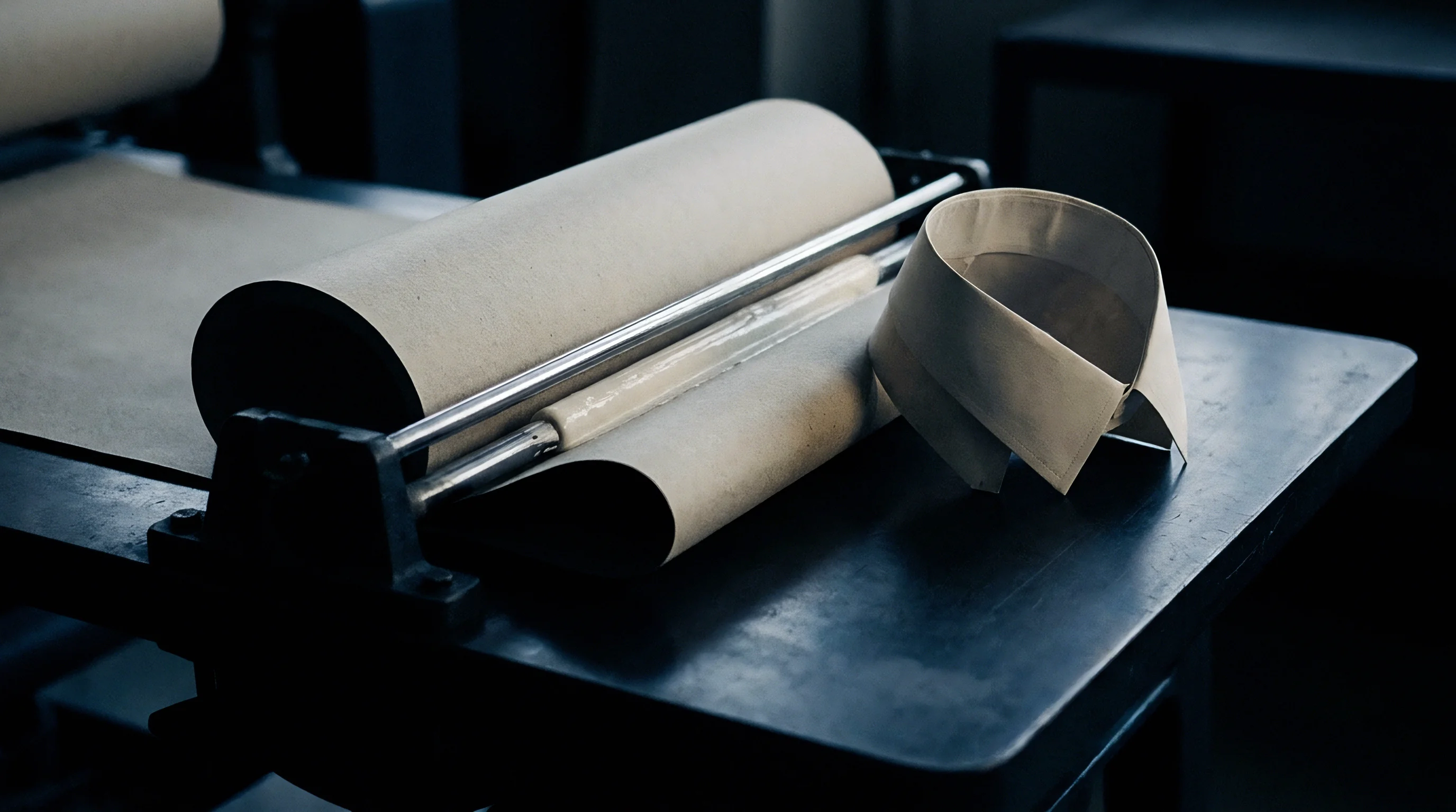

Substrate
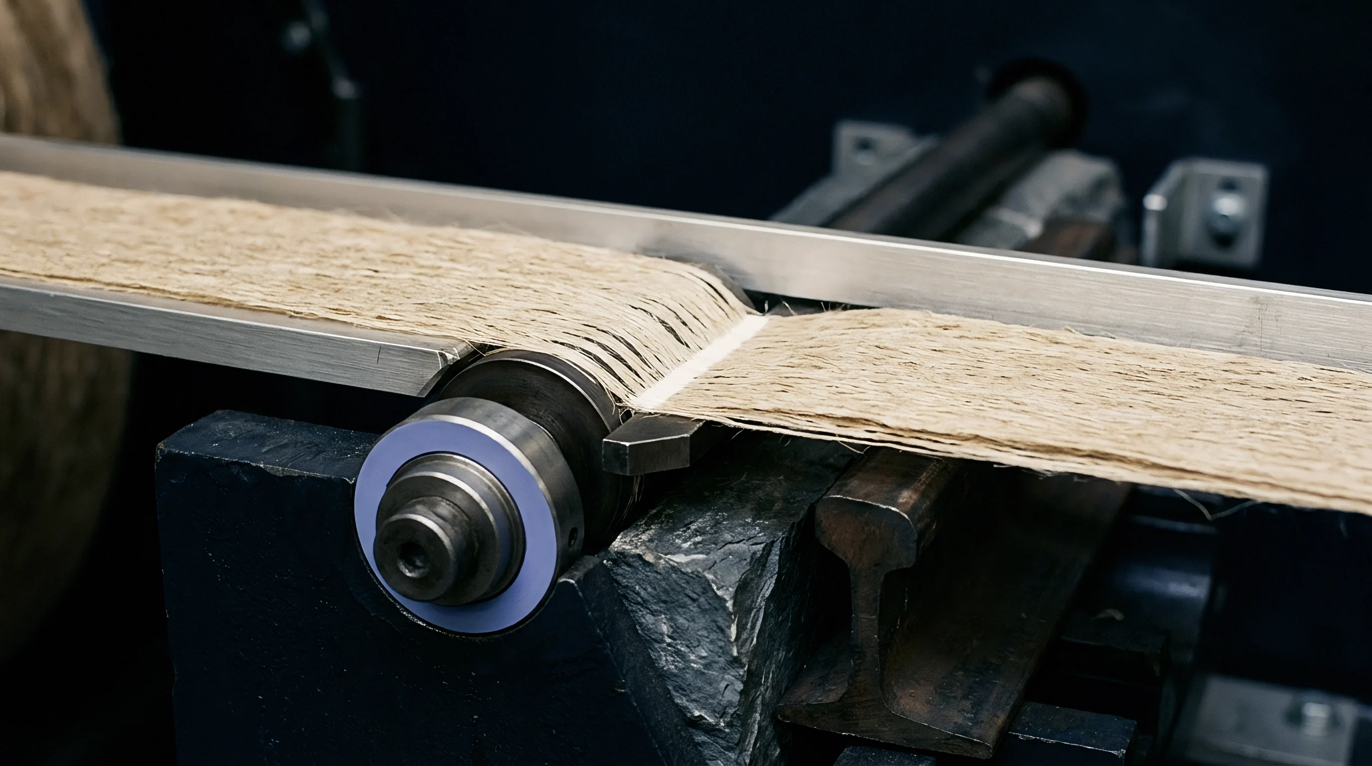
Fiber Composition and Ply Architecture
Folding cartonboard uses multi-ply construction to handle mechanical stresses during conversion and folding. Creasing performance depends directly on z-direction bond strength, fiber orientation ratio, and density variations between outer linerboard layers and inner bulk plies. Solid Bleached Sulfate consists of multiple layers of bleached chemical pulp, giving it uniform density and z-directional tensile strength ranging from 250 to 450 kilopascals under ISO 1924 testing.
Folding Boxboard places mechanical or thermomechanical pulp in middle layers sandwiched between outer layers of bleached chemical pulp. This layout concentrates bending stiffness in outer faces while maintaining high bulk in central layers, though lower z-direction bond strength inside the mechanical pulp layers alters structural deformation during score blade impact.
Recycled grades, including Coated Recycled Board and White Lined Chipboard, rely on short, repeatedly refined secondary fibers mixed with filler. Ash content above 12 percent by weight degrades fiber bonding, leading to erratic delamination when steel creasing blades strike the sheet. Moisture content governs polymer chain flexibility inside wood cellulose, controlling overall ply compliance.
Standard conditioning under ISO 187 at 23 degrees Celsius and 50 percent relative humidity stabilizes paperboard equilibrium moisture between 6.5 percent and 8.5 percent by weight. Dropping below 5.5 percent moisture hardens the lignin matrix, raising crack susceptibility on printed liners. Exceeding 9.0 percent moisture weakens shear resistance across internal plies, producing spongy creases that fail to form sharp 90-degree carton corners on high-speed folder-gluers.

Mechanical Properties and Standard Test Conditions
Evaluating board structural performance requires quantifying machine-direction and cross-machine-direction stiffness ratios. Fiber alignment on the wet end of the paper machine aligns cellulose strands along the machine direction, yielding stiffness ratios from 1.5-to-1 up to 3.0-to-1 against the cross direction. Creasing perpendicular to the machine direction bends fibers across structural axes, demanding higher scoring energy and wider matrix channels.
Creasing parallel to the machine direction compresses long fiber bundles laterally, which increases the risk of outer liner shear splitting if matrix channel depth is sized incorrectly.
| Grade Family | Caliper Range (mm) | Density (g/cm³) | Z-Tensile (kPa) | Taber Stiffness MD (mN·m) | Cobb 60 Outer (g/m²) |
|---|---|---|---|---|---|
| Solid Bleached Sulfate | 0.30 to 0.65 | 0.80 to 0.95 | 320 to 480 | 3.5 to 28.0 | 25 to 35 |
| Folding Boxboard | 0.35 to 0.80 | 0.55 to 0.75 | 180 to 290 | 4.0 to 35.0 | 28 to 40 |
| Coated Recycled Board | 0.40 to 0.75 | 0.70 to 0.85 | 140 to 240 | 2.8 to 22.0 | 35 to 55 |
| Solid Unbleached Board | 0.35 to 0.70 | 0.75 to 0.88 | 350 to 520 | 5.0 to 38.0 | 20 to 30 |
Taber 15-degree bending stiffness measurements under TAPPI T 489 or ISO 2493 establish initial board bending resistance. High bending stiffness in thick board grades demands deeper creasing rule penetration to force internal shear failure. Crease performance relates directly to residual bending moment after score formation.
An uncreased paperboard sample exhibits a specific bending stiffness curve; an optimally creased board displays a moment drop between 50 percent and 70 percent of initial uncreased bending resistance when folded through 90 degrees on a crease stiffness tester like the Marbach or L&W Crease Tester.
When relative humidity drops below 40 percent, pliable cellulose fibers turn brittle and surface liner cracking rates spike across high-speed automatic die cutters.
Surface coatings add structural resistance during scoring. Triple-coated mineral clay barriers bound by styrene-butadiene or acrylic latex binders increase surface modulus of elasticity. Scoring operations must force clay coatings to yield plastically without micro-cracking.
Coating weight distributions above 25 grams per square meter increase top-liner brittleness, forcing conversion lines to widen matrix channels by 0.05 to 0.10 millimeters relative to uncoated board stock of identical caliper.
Film laminations alter scoring mechanics entirely. Polyethylene terephthalate, oriented polypropylene, and cellulose acetate films applied over printed sheets act as continuous tensile membranes. While film layers inhibit outer surface fiber tearing, high film tensile strength prevents clean crease bead formation if matrix width is tight.
Thin plastic films stretched over wide matrix channels snap back post-stamping, causing panel bow and squareness failures in final pack assemblies. Matching film tensile properties to board ply shear capability avoids production scrap on high-speed automatic lines.
Running board stock with moisture content outside standard ranges creates conversion instability. Dry sheets split at the outer plies when passed beneath narrow creasing rules.


Rule
Steel Blade Profile and Tip Geometry
Creasing rule steel specifications dictate how force transfers into paperboard plies during die impact. Standard steel scoring rules feature a ground or drawn top profile in hardened carbon steel rated between 35 and 45 Rockwell C. Rule thickness uses point system nomenclature where 1 point equals 0.014 inches or 0.356 millimeters. Standard sizes include 1.5 point (0.53 mm), 2 point (0.71 mm), 3 point (1.05 mm), 4 point (1.42 mm), and 6 point (2.13 mm).
Edge geometries range from full round profiles to flat chamfered edges and trapezoidal crowns.
Full round rule profiles concentrate vertical penetration force along the center axis of the score line. They push paperboard down into counter-matrix channels, generating uniform tensile elongation across top liners while creating symmetrical shear bands inside middle plies. Flat-faced rules distribute penetration pressure across a wider area, reducing top liner compression while increasing corner shear stress at the shoulder radii.
Tip radius selection depends directly on board thickness and coating ductility.
Rule Height Mechanics and Impression Depth
Steel height selection inside platen dies relies on die-cutting steel rule height as the primary baseline. Standard cutting rule height measures 23.80 millimeters (0.937 inches) in European and Asian press configurations, or 23.88 millimeters (0.940 inches) in American configurations. Creasing rule height sits lower than cutting rule height to prevent cutting through board fibers.
The height differential between cutting rule and creasing rule equals board thickness plus matrix counterplate allowance, modified by desired crease depth.
Excessive rule height crushes paperboard fibers into a solid mass, destroying internal ply structures and tearing bottom liners. Insufficient rule height leaves shallow score beads that fail to lower folding resistance, causing carton panels to bulge during automatic assembly. Impression adjustments on automatic flatbed die cutters alter crease depth across entire sheet layouts.
Precision make-ready paper placed behind die-chase plates compensates for localized press bed deflection, holding creasing rule penetration depth within a tight tolerance band of plus or minus 0.015 millimeters across the working surface.
Improper matching of rule width to board caliper creates predictable conversion failures on finishing lines:
- Liner Splitting along Score Line occurs when the tip radius is too narrow, cutting top surface fibers instead of stretching them into matrix channels.
- Rolling Crease Bead Formation results from excessive clearance inside matrix channels, allowing score beads to shift laterally off-center.
- Shear Separation at Inner Corner emerges when creasing rule penetration depth exceeds internal ply shear capability, causing complete structural tearing.
- Asymmetric Fold Resistance develops when creasing rule positioning drifts off-center relative to matrix channel centerlines, distorting fold geometry.
Matrix counter channels receive creasing rule protrusions during press bottom-dead-center dwelling. High-speed flatbed die-cutters running at 9,000 sheets per hour produce contact dwell times under 15 milliseconds. Steel rules must deform paperboard plies plastically within this short window.
Carbon steel rules under continuous dynamic loading experience tip flattening over long production runs. A tip flat exceeding 0.08 millimeters widens effective scoring geometry, altering internal delamination patterns and increasing carton fold resistance.
Specialty rules solve specific substrate challenges. Crease-cut combination rules alternate cutting and scoring segments to handle heavy laminated micro-flute corrugated stock. Coated rules with low-friction titanium nitride surfaces prevent ink dragging and coating pick-off on heavy solid black printed sheets.
Standard rule configurations work predictably when maintained within manufacturer profile tolerances.
While wider creasing rules are intended to eliminate score cracking across recycled board grades regardless of matrix sizing, widening rule width without corresponding matrix channel adjustments distorts crease geometry, degrading fold performance across automated packaging lines.

Delamination

Internal Shear Stress Mechanics
Creasing forces trigger controlled internal shear failure within central board plies. When steel scoring rules press into sheet surfaces, top liners experience combined tensile and bending stress. Inner plies directly beneath rule tips undergo vertical compression and horizontal shear stress.
Bottom liners, pressed down into matrix channels, take on bending tension across channel shoulders. Controlled delamination separates internal fiber networks into multiple thin, flexible sub-layers. These unbonded sub-layers slide across one another during folding, keeping outer surface liners from snapping under tension.
Failing to achieve internal delamination leads to top liner cracking or back-liner splitting upon 90-degree or 180-degree folding. When internal plies remain solidly bonded, paperboard behaves as a single thick beam. Standard beam bending mechanics dictate that outer surface strain equals half the board thickness divided by neutral axis bending radius.
High surface strain exceeds cellulose failure limits, fracturing printed ink films and clay coatings. Internal delamination splits that single thick beam into multiple thin independent layers, reducing surface strain proportionately.
Z-direction shear stress reaches peak intensity at roughly 45-degree angles from creasing rule shoulders toward matrix channel bottom corners. Fiber bonds inside mechanical pulp middle layers split along these shear planes, creating internal voids visible under cross-sectional microscopic analysis. Mechanical shear failure absorbs applied press force, permanently altering paperboard internal structural memory.

Score Bead Formation and Microstructural Changes
Forming precise crease beads requires balanced force transfer into matrix channel voids. Downward movement of scoring rules forces paperboard down into channel cavities, forming rounded female score beads on reverse sides of sheets. Counter-channel depth determines score bead projection height.
Male rule profile and female channel width establish shoulder clearance parameters, governing double-shear deformation zones.
Cross-sectional analysis of properly formed creases reveals specific structural regions. Under rule tips, high compression densifies top fibers, creating smooth internal male indents. Across shoulder edges, fibers stretch without breaking.
Inside central cores, fiber plies display delaminated separation gaps extending horizontally past creasing zone boundaries. On reverse sides, intact bottom liners form defined convex score beads matching channel shapes.
Test trials verified that board samples exhibiting delamination zones extending 0.5 to 0.8 millimeters laterally beyond crease shoulders yield optimal fold resistance drops, lowering 90-degree folding force by 62 percent compared to uncreased controls.
Fiber shear behavior depends heavily on refine levels during pulp preparation. Over-refined chemical pulps yield dense, tightly bonded internal layers that resist delamination, requiring higher mechanical penetration force that risks cutting outer liners. Under-refined pulps delaminate easily but lack structural cohesion, causing loose crease beads that collapse under glue-flap compression forces on high-speed side-seam gluers.
Scoring printed surfaces requires balancing ink coating elasticity against paperboard delamination thresholds. Energy curing UV inks and overprint varnishes increase surface film brittleness. When scoring rules press into UV-printed top liners, outer ink coatings must stretch along tensile zones.
If internal delamination occurs too late during rule penetration, outer ink films shatter before paperboard plies shear apart internally. Coordinating matrix channel clearance with ink film cross-linking density prevents white line fracture defects along finished carton edges.
Selecting incorrect scoring geometry destroys internal delamination integrity, generating brittle fractures across folded carton edges that yield high scrap rates during final product filling.

Channel

Matrix Channel Sizing Formulas and Equations
Determining matrix channel width and depth relies on exact mathematical relationships incorporating board thickness, creasing rule thickness, and substrate material parameters. Standard channel sizing calculations utilize specific multiplier factors to establish ideal clearance for internal delamination without creating loose score beads.
Matrix channel depth calculation follows a fundamental direct relationship to sheet caliper:
Matrix Depth = Board Caliper
For solid paperboard grades (SBS, FBB, CRB) ranging from 0.30 to 0.75 millimeters, matrix depth equals board thickness directly. For heavy board grades above 0.75 millimeters or micro-flute corrugated stock (E-flute, F-flute), matrix depth equals 0.70 to 0.85 times sheet thickness to account for structural void collapse during compression.
Matrix channel width calculation requires incorporating rule thickness alongside sheet thickness parameters:
Matrix Width = (Factor × Board Caliper) + Creasing Rule Thickness
The multiplier factor varies based on fiber orientation, pulp type, and liner coating ductility. Standard conversion calculations set the multiplier factor to 1.5 for cross-machine direction creasing on standard SBS board. For machine-direction creasing on stiff or dry board, the multiplier factor increases to 1.7 or 1.8.
For soft or high-recycled content board (CRB, WLC), the multiplier factor reduces to 1.3 or 1.4 to maintain tight score bead control.
| Board Caliper (mm) | Board Caliper (pt) | Creasing Rule Width (mm) | Calculated Matrix Width (mm) | Selected Matrix Depth (mm) | Recommended Matrix Type |
|---|---|---|---|---|---|
| 0.30 | 12 | 0.71 (2 pt) | 1.16 to 1.22 | 0.30 | Phenolic / Film-Backed Base |
| 0.40 | 16 | 0.71 (2 pt) | 1.31 to 1.39 | 0.40 | Pressboard / Phenolic Channel |
| 0.50 | 20 | 0.71 (2 pt) | 1.46 to 1.56 | 0.50 | Pressboard / Cut Steel Counter |
| 0.60 | 24 | 1.05 (3 pt) | 1.95 to 2.07 | 0.60 | Milled Steel / Phenolic Counter |
| 0.70 | 28 | 1.05 (3 pt) | 2.10 to 2.24 | 0.70 | Milled Steel / Phenolic Counter |
| 0.80 | 32 | 1.42 (4 pt) | 2.62 to 2.78 | 0.80 | Milled Steel Counterplate |
What Sizing Ratio Prevents Liner Splitting?
Preventing liner splitting requires maintaining channel width ratios within narrow boundaries relative to total board caliper. Ratios under 1.3 times board caliper plus rule width create severe double-shear pinch points at channel shoulders that cut outer liner fibers before internal plies can delaminate. Ratios above 1.9 times board caliper plus rule width leave wide, unsupported spans where paperboard bows downward without generating internal shear stress, producing shallow, weak creases with high spring-back forces.
Calculating clearance parameters between creasing rule sides and matrix channel shoulders defines internal deformation volume:
Side Clearance = (Matrix Width – Creasing Rule Thickness) / 2
Ideal side clearance equals 0.65 to 0.85 times board thickness. Operating within this clearance envelope ensures board fibers fold smoothly around matrix shoulder edges, creating balanced, low-resistance crease joints.
Converting lines follow a systematic procedure to establish matrix channel sizing during die make-ready operations:
- Measure sheet thickness across ten points using a calibrated dead-weight micrometer per ISO 534 standards to establish average board caliper.
- Determine sheet grain orientation relative to die layout lines, identifying machine-direction and cross-machine-direction score locations.
- Calculate theoretical matrix channel widths for both sheet directions using standard multiplier equations based on pulp classification.
- Select matrix strips or milled steel counterplate plates matching calculated channel widths and depths within plus or minus 0.03 millimeter tolerances.
- Mount matrix strips onto cutting plates using locator keys attached to die creasing rules, pulling press pressure to transfer strips into register.
- Peel away carrier locator strips and clean matrix channels, removing residual adhesive or paper dust prior to production scoring.
- Run initial sample sheets under impression pressure, checking crease stiffness reduction and microscopic cross-sectional delamination.
Matrix sizing calculations must adapt when running film-laminated board. Plastic films added to outer board surfaces increase tensile strain capacity. When scoring film-laminated board, decreasing matrix channel width by 0.10 millimeters relative to standard paperboard formulas compresses score beads tightly, preventing film delamination along folded carton edges.
Standard ISO 2493 stiffness testing mandates that properly sized matrix channels achieve a minimum 50 percent drop in crease bending resistance relative to uncreased board stock.
Contractual specifications must define exact matrix channel sizing formulas and measurement protocols to resolve production quality disputes. Standard packaging supply agreements specify that matrix channels must hold dimensions within plus or minus 0.02 millimeters across total production run lengths. Incorporating explicit matrix sizing tolerances into purchase orders prevents delivery of cartons exhibiting variable fold stiffness and corner cracking defects.


Tolerance

Matrix Strip Materials and Wear Dynamics
Selecting matrix materials dictates structural channel dimensional stability across extended die-cutting production runs. Pressboard matrix strips consist of vulcanized micro-ply paper fibers coated with pressure-sensitive adhesive. Synthetic plastic matrix strips utilize extruded polyvinyl chloride or micro-composite polymers.
Phenolic resin matrix channels utilize paper-reinforced thermosetting resins milled into rigid channel strips. Milled steel counterplates utilize hardened sheet steel etched or CNC-milled to produce exact counter-channel networks across whole die sheets.
Material selection governs channel wall deflection under high-speed press impacting. Pressboard matrix strips provide economical setup costs for short production runs under 20,000 impressions. Under continuous press impact, pressboard channel shoulders round off, widening channel width by 0.05 to 0.12 millimeters after 30,000 sheets.
Synthetic plastic matrix strips withstand impact forces across mid-sized runs, holding channel geometry up to 100,000 sheets. Phenolic resin strips resist shoulder deformation across high-volume runs up to 500,000 sheets. Milled steel counterplates provide maximum channel permanence, maintaining dimensional tolerances across multi-million sheet production contracts.
| Matrix Material | Base Material Composition | Maximum Run Life (Sheets) | Width Drift at 50k Impressions (mm) | Thermal Expansion Coeff. (10⁻⁵/K) | Relative Tooling Cost Index |
|---|---|---|---|---|---|
| Pressboard | Vulcanized Paper Fiber | 25,000 | +0.08 | 1.2 | 1.0 |
| Extruded PVC | Polyvinyl Chloride Plastic | 100,000 | +0.04 | 7.5 | 1.8 |
| Phenolic Laminate | Paper-Reinforced Thermoset | 500,000 | +0.01 | 1.8 | 3.5 |
| Milled Steel | Hardened Carbon Steel Sheet | 2,000,000+ | 0.00 | 1.1 | 12.0 |
Thermal expansion during press operation alters channel positioning accuracy. Large-format flatbed die-cutters generate internal heat through friction and mechanical drive operation, raising press plate temperatures by 10 to 18 degrees Celsius over standard ambient baseline temperatures. Plastic matrix strips with high thermal expansion coefficients expand laterally, narrowing channel openings and distorting crease registration across outer sheet layouts.
Phenolic and steel counterplates match steel chase thermal coefficients, holding registration across long shifts.
Die Alignment and Register Precision
Register alignment between creasing rules and matrix channels governs score line symmetry. Centerline mismatch between male rule tips and female matrix channels causes asymmetric crease formation. When creasing rules land off-center by more than 0.05 millimeters relative to matrix channels, internal shear forces concentrate entirely on one channel shoulder.
The high single-sided shear force tears outer liners on narrow clearance sides while producing loose, un-delaminated board on wide clearance sides.
Die-cutting press positional accuracy relies on precise mechanical tolerances across multiple components:
- Die Chase Locking Tolerance governs positional repeatability of cutting dies inside press upper platens.
- Cutting Plate Register Pins locate lower matrix plates relative to upper die chases.
- Matrix Strip Locator Wings align individual matrix channels over steel scoring rules during mounting.
- Sheet Gripper Bar Precision controls paperboard sheet positioning between upper die rules and lower counterplates.
Accumulating mechanical tolerances across these components creates total registration variance. High-speed automatic die-cutters hold total registration variance within plus or minus 0.10 millimeters when running optimal make-ready procedures. Exceeding 0.15 millimeters total register drift induces visible score bead distortion, causing finished packaging cartons to twist during automatic folder-gluer operations.
Evaluating score quality during production runs requires systematic sampling protocols. Quality inspectors pull full sheets every 5,000 impressions, testing crease stiffness using automated instruments and inspecting score cross-sections under optical magnifiers. Quantifying crease depth, score bead height, and internal delamination width confirms score line integrity throughout long production runs.
Omitting matrix channel wear limits from purchase orders on long jobs frequently leads to carton squareness failures. On a 500,000-sheet run, progressive wear on pressboard channels can alter crease stiffness by 40 percent, triggering automatic gluer jams and costly downtime.
How do thermal growth variations across large-format platen plates alter dynamic scoring clearance when running synthetic matrix strips on three-shift packaging production runs?


Interface
Automatic Packaging Line Performance
Transferring creased carton blanks to automated high-speed packaging equipment puts conversion mechanics to the test. Modern packaging machinery demands precise carton squareness, consistent opening force, and low side-seam fold resistance. High-speed side-seam folder-gluers run at belt speeds exceeding 400 meters per minute, folding and gluing up to 100,000 cartons per hour.
Automatic end-load cartoning lines erect flat-folded cartons, load products, and tuck closing flaps at speeds up to 500 cartons per minute. Inconsistent crease stiffness across carton score lines causes machine misfeeds, panel bowing, and high line shutdown rates.
Carton opening force correlates directly with score line delamination quality. When flat-folded cartons enter erection stations on automatic cartoning lines, vacuum suctions pull main panels apart to form 90-degree rectangular structures. Opening force instruments measure peak mechanical resistance encountered during this erecting stroke.
Properly creased cartons exhibit low, consistent opening forces between 0.5 and 1.5 Newtons. Improperly creased cartons with incomplete internal delamination require opening forces exceeding 3.0 Newtons. High opening force causes carton blanks to slip past vacuum cups, causing line stoppages and crushed carton blanks.
Score line memory creates spring-back forces that fight carton squareness. After folding, paperboard cellulose fibers act as internal micro-springs, attempting to push folded panels back toward flat sheet states. Effective matrix channel sizing and rule penetration maximize permanent plastic deformation, lowering elasticity inside crease joints.
Holding post-folding spring-back forces below 0.3 Newtons per meter of crease length maintains true 90-degree corner geometry, ensuring filled cartons stack cleanly on pallets without bulging or leaning.

Commercial Mechanics and Cost Trade-Offs
Optimizing creasing tooling involves balance between make-ready expense, material durability, and operational running efficiency. Selecting matrix tooling systems impacts total job production costs through initial setup time, tooling material unit costs, press running speeds, and waste rates.
Individual matrix strips offer low upfront material expenses for small packaging runs. Installing individual strips across a complex 50-up folding carton layout requires skilled hand labor, taking press operators up to 90 minutes to align locator keys, bond channels, and trim corners. Manual setup labor costs accumulate rapidly on short-run digital and offset packaging jobs.
Integrated phenolic or steel counterplates require higher initial tooling investment but reduce press make-ready setup times to under 15 minutes. Slide-in counterplates index directly onto press locator pins, eliminating hand key alignment entirely.
Production run economics dictate tool selection boundaries. Jobs under 10,000 sheets justify individual pressboard matrix strips. Mid-sized production runs between 10,000 and 100,000 sheets warrant synthetic plastic or phenolic matrix strips.
High-volume repeat packaging contracts running above 250,000 sheets demand dedicated CNC-milled steel counterplates. Steel counterplates ensure identical crease geometry across initial runs and subsequent reprints, eliminating variable carton erection issues on buyer packaging lines.
Spoilage rates on high-speed folder-gluers drop significantly when utilizing precision counterplate tooling. Poor score line formation causes mis-folding along glue flaps, producing out-of-square cartons that fail quality checks. A 1.5 percent increase in carton spoilage on a 500,000-sheet production run of high-end coated paperboard wastes thousands of dollars in raw substrate, printed ink, and laminating film costs.
Spending extra upfront tooling capital on milled steel counterplates pays back through higher press running speeds, lower scrap rates, and consistent conversion quality across full production lifecycles.
Calculating the true cost of creasing choices requires evaluating total process expenses across pre-press tooling, die make-ready labor, press running speed, waste factors, and downstream packaging line efficiency. Skimping on matrix channel sizing or tooling quality increases total pack unit cost through accumulated scrap and lost machine productivity.