Optimizing Die Cutting Matrix Dimensions for Heavyweight Folding Boxboard Grades
Heavyweight folding boxboard requires matrix depth matching board caliper and channel width calculated at one point seven times caliper plus rule thickness.
Groove
Die cutting multi-ply paperboard grades requires severe localized deformation along defined fold lines. Heavyweight folding boxboard grades ranging from four hundred to eight hundred micrometers in caliper feature a layered construction. Bleached chemical pulp outer layers enclose a bulky, stiff mechanical pulp center.
Creating a clean score line without rupturing outer surface coatings demands controlled internal structure collapse. Multi-ply boards demand precise crease mechanics. Creasing rules push board fibers downward into an open matrix channel, forcing the mechanical middle layer to delaminate internally while outer chemical plies stretch smoothly over channel edges.

Mechanical Deformation Dynamics
In heavy boxboard substrates, high thickness accentuates outer ply tension during bending. When matrix channel widths run too narrow, female channel shoulders pinch outer chemical liners, causing surface blade cracks or total liner rupture. Thick boards resist tight bending.
Conversely, channels that run too wide fail to isolate internal shear stresses, producing wide, sloppy fold lines and double-crease ridges that destabilize automated carton folding machinery.
Board moisture content above seven percent softens the mechanical core and permits narrower channel widths without surface fracturing.
Matrix channel depth directly influences compression force along the crease root. If depth falls short of sheet thickness, score rules crush the mechanical core excessively, weakening the board structure and lowering carton stacking strength. Proper matrix geometry balances channel depth against sheet caliper while widening channel shoulders to accommodate displaced bulk.
| Board Caliper (µm) | Basis Weight (gsm) | Crease Rule Pt | Matrix Depth (mm) | Matrix Width (mm) |
|---|---|---|---|---|
| 450 | 320 | 2 Pt (0.71 mm) | 0.45 | 1.50 |
| 550 | 380 | 3 Pt (1.05 mm) | 0.55 | 2.00 |
| 650 | 440 | 3 Pt (1.05 mm) | 0.65 | 2.20 |
| 750 | 510 | 4 Pt (1.42 mm) | 0.75 | 2.70 |
Selecting appropriate channel dimensions ensures clean board delamination across varying mechanical pulp densities. Incorrect channel selection splits outer liners, generates ragged crease contours, and forces premature job stops across automated packaging lines.


Platen
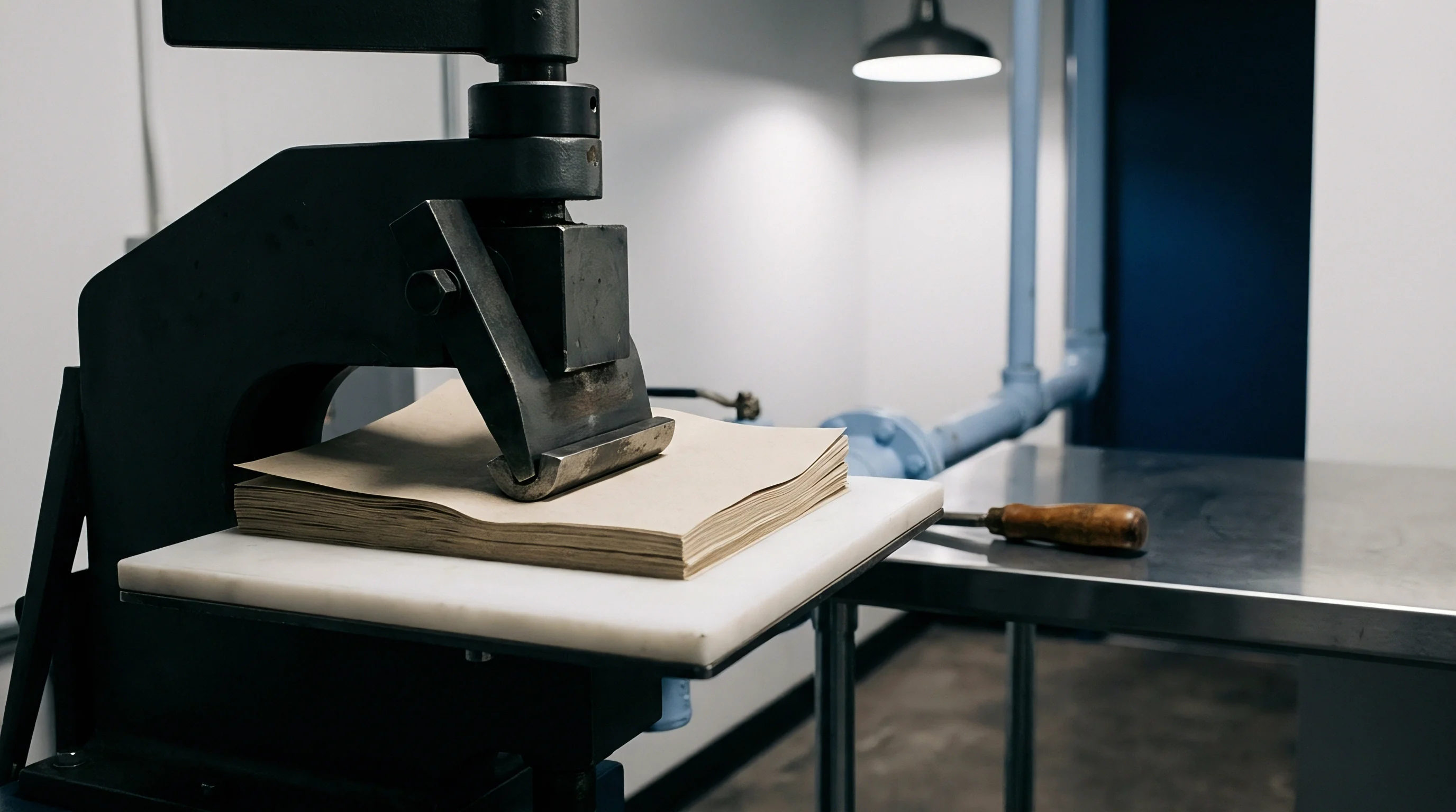
Flatbed converting presses generate high compressive forces to drive steel rule knives and scoring tools into board stock. Die pressure distribution must remain completely flat across the bed to maintain consistent matrix depth penetration. Scoring depth governs line precision.
Minor bed deviations alter impression forces, causing inconsistent scoring performance across large sheet layouts.

Impression Depth Calibration
Rule penetration depth dictates how cleanly scoring edges form. Excessive tool penetration crushes matrix shoulder walls, displacing sticky adhesive carrier strips and causing sheet feeder jams. Insufficient tool pressure fails to form a deep crease root, forcing downstream folder-gluer stations to crack stiff boxboard edges.
Make-ready patch paper placed beneath steel bed plates corrects minor pressure variations across press zones.
- Clean impression plate with isopropyl alcohol to clear oil residue.
- Apply phenolic matrix strips along steel die scoring channels.
- Run single press stroke at minimum tonnage to locate matrix position.
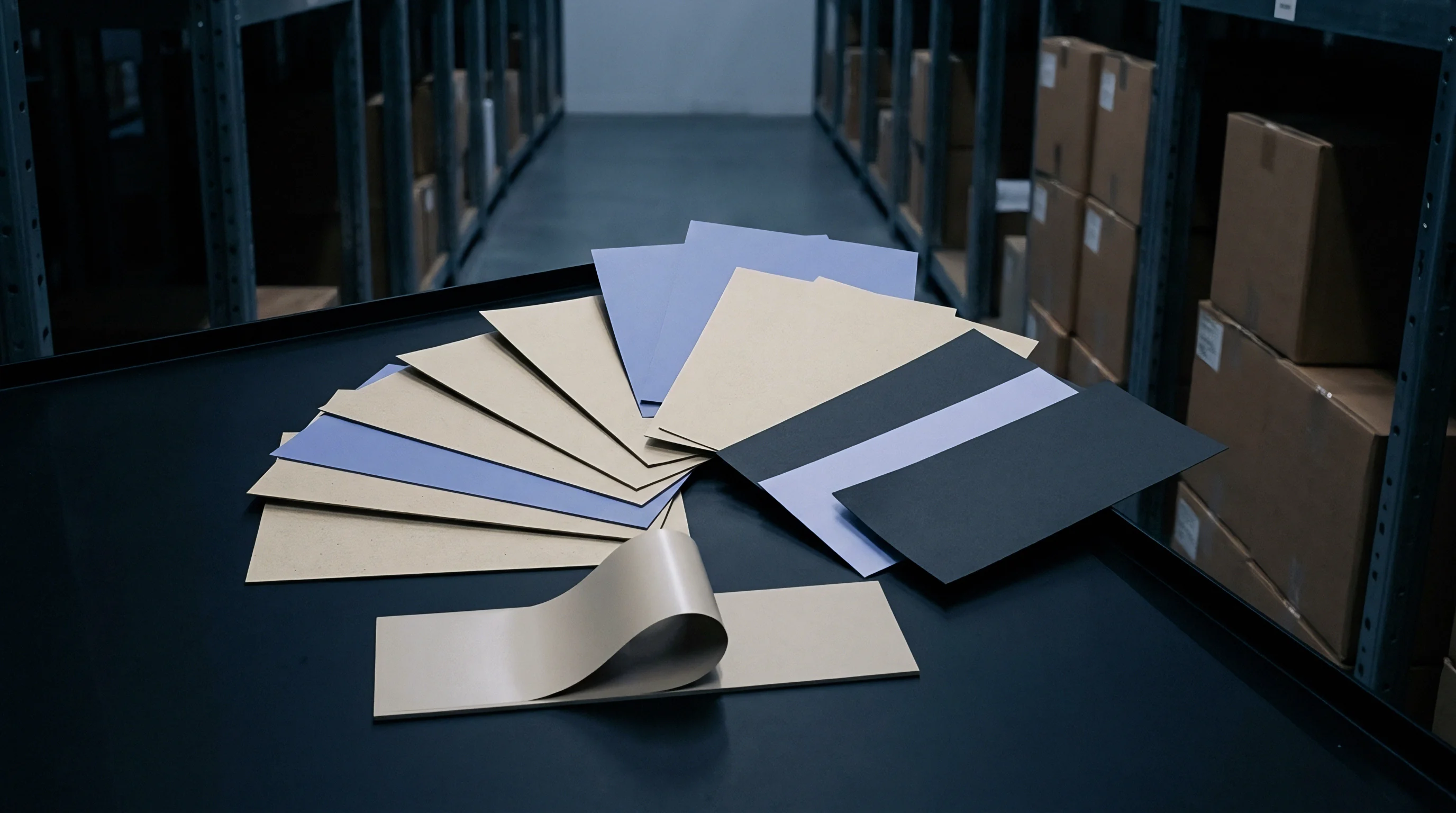
- Peel backing tape film from matrix shoulders.
- Increase cutting pressure in steps of five hundredths of a millimeter until cut rules penetrate cleanly through rear liner.
- Level scoring depth across sheet quadrants using targeted paper patch layers under cutting plate.
Rule edge geometry alters penetration behavior under pressure. Standard sharp center-bevel rules cut easily but concentrate shear forces on top liners. Heavy gauges multiply press tonnage.
Crowned round-top scoring rules distribute force over a broader radius, reducing surface fracture risks on heavy coated virgin fibre boards. Ruptured coatings destroy pack appearance.
Mill technical teams frequently attribute score cracking to ambient humidity fluctuations rather than press impression depth errors.
Caliper
Paperboard thickness dictates the physical volume of material displaced into scoring channels. Heavyweight boxboard grades exhibit pronounced directional stiffness due to cellulose fiber alignment along the paper machine running direction. Cross-grain folds demand wider channels.
Scoring across the grain forces stiff longitudinal fibers to bend abruptly, requiring larger channel clearances to prevent surface tearing. Folds running parallel to machine grain flex easily, allowing narrower channels.

Which Creasing Rule Thickness Prevents Liner Bursting?
Selecting rule width depends on outer liner elongation properties. Thin two-point rules concentrate scoring force along a narrow point, exceeding elongation limits on thick boards above five hundred micrometers. Three-point and four-point rules broaden contact surfaces, bending outer liners across a gentler curve.
Round rules reduce peak stress.
Standard DIN 53121 laboratory testing establishes that crease stiffness decreases proportionally as matrix channel width expands beyond one point eight times sheet caliper.
Substrate moisture content alters fiber elasticity during impact. Low ambient pressroom humidity dries board outer liners, making top clay coatings brittle and prone to micro-cracking under score rules. Dry boards fracture more easily.
Maintaining pressroom air at fifty percent relative humidity preserves natural fiber flexibility, expanding working tolerances for matrix dimensions.
| Board Caliper (µm) | Channel Factor | Channel Width (mm) | Uncreased Resistance (mN) | Crease Stiffness (mN) |
|---|---|---|---|---|
| 500 | 1.4x | 1.75 | 420 | 185 |
| 500 | 1.7x | 1.90 | 420 | 130 |
| 700 | 1.4x | 2.40 | 890 | 390 |
| 700 | 1.7x | 2.60 | 890 | 270 |
| Testing conditions: ISO 187 conditioning at 23°C and 50% RH using 15-degree bending resistance test per DIN 53121. | ||||
Improper channel sizing manifests in distinct board converting failure profiles that compromise packaging line efficiency.
- Liner Fracturing occurs when tensile extension on outer bleached chemical ply exceeds ultimate elongation limits during matrix entry.
- Crease Rolling manifests as secondary crease ridges alongside main score line when matrix channel width provides excessive lateral clearance.
- Delamination Shear Failure results from insufficient compression depth failing to break internal bonds within mechanical pulp core.
- Matrix Adhesive Displacement develops when lateral shoulder forces detach matrix strips from press plate during high-speed production runs.
Wider scoring channels preserve outer liner integrity at the expense of precise carton fold squareness.
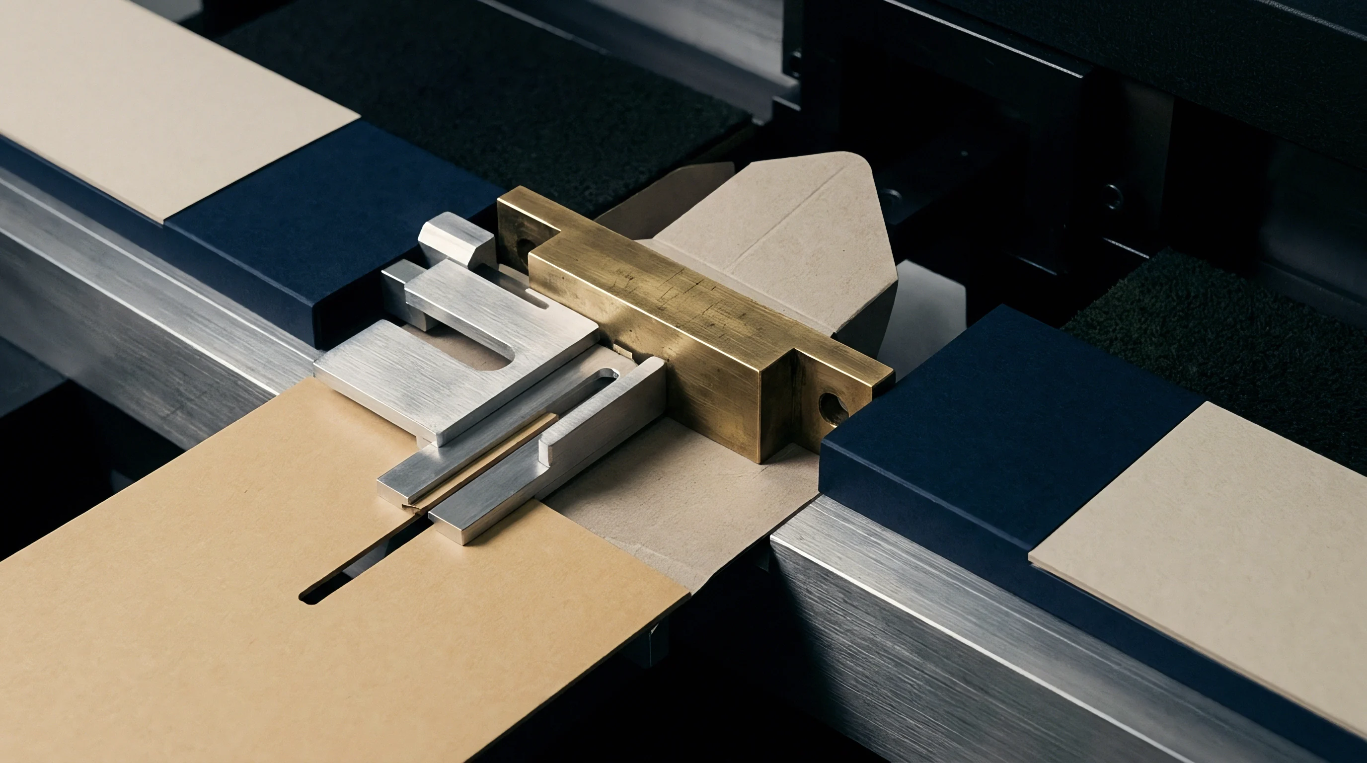

Geometry
Mathematical formulas provide exact matrix dimensions from substrate thickness measurements. Calculating channel width uses sheet caliper, creasing rule thickness, and an empirical multiplier reflecting board fiber flexibility. Channel depth matches nominal board caliper or stays slightly below to compensate for initial mechanical pulp compression.

Channel Width Mathematical Calculation
Determining scoring channel width relies on multiplying sheet caliper by an empirical factor, then adding the steel rule thickness. Cross-grain folds require a factor between one point six and one point eight for heavyweight folding boxboard. Folds running parallel to machine direction use a reduced factor between one point four and one point six.
Calculating channel width for a six hundred fifty micrometer board folded cross-grain with a three-point creasing rule demonstrates this relationship. Applying the cross-grain factor of one point seven to the zero point six five millimeter caliper yields one point one zero five millimeters. Adding the three-point rule width of one point zero five millimeters produces a required channel width of two point one five millimeters.
Matrix depth matches board thickness at zero point six five millimeters, selecting a commercial matrix sized at zero point six five by two point two zero millimeters.
Calculated channel width expands by zero point two millimeters when board moisture drops below five point five percent.
Calculating along-grain channels on the same board utilizes the lower factor of one point five. Multiplying zero point six five millimeters by one point five produces zero point nine seven five millimeters. Adding rule thickness yields two point zero two millimeters channel width.
The resulting matrix specification shifts to zero point six zero by two point zero zero millimeters.
- Substrate Thickness Measurement requires mechanical micrometer readings across five board locations under standard atmospheric conditioning.
- Grain Direction Verification demands tensile stiffness testing along both sheet axes before committing tooling specifications.
- Rule Profile Selection involves matching crown radius to board liner coating elasticity limits.
- Channel Width Allocation combines caliper multipliers with exact steel rule point sizing for cross-grain lines.
Hard matrix walls preserve channel edges. Press speed alters creasing forces. Whether dynamic press speed adjustments can offset tight channel tolerances on low-moisture boards remains an open question across high-volume converting facilities.

Ledger
Tooling economics balance initial make-ready expense against total production output. Phenolic resin matrix strips offer quick setup times for short-to-medium runs. High-speed long runs justify laser-milled steel counterplates that maintain fixed channel width geometry across hundreds of thousands of impressions.

Tooling Material Selection Economics
Matrix channel durability varies significantly across underlying substrate materials. Standard plastic matrices deform under prolonged platen pressure, broadening channel widths and causing score drift over extended runs. Phenolic matrix options retain crisp shoulder profile geometry longer, preventing score cracking during long production shifts.
Premium counterplates reduce job setup waste while increasing fixed upfront die tooling investment.
| Matrix Material | Tooling Unit Cost | Make-Ready Time (min) | Life Expectancy (sheets) | Score Width Drift (mm) |
|---|---|---|---|---|
| Standard PVC Matrix | Low | 25 | 20,000 | 0.15 |
| Phenolic Resin Matrix | Moderate | 20 | 50,000 | 0.05 |
| Milled Steel Counterplate | High | 5 | 500,000 | 0.00 |
Verification documentation secures predictable converting performance before tooling approval.
- CAD Tooling Layout specifies creasing rule heights and points across every panel junction.
- Substrate Certificate Dossier records exact caliper tolerances and moisture percentage ranges per mill batch.
- Matrix Channel Schedule identifies width and depth combinations matching cross-grain and long-grain score lines.
- Press Setup Record logs platen impression depth adjustment values and make-ready tissue layer counts.
Tooling costs reflect channel precision. Selecting milled counterplates eliminates manual matrix alignment errors, saving press make-ready time while securing tight score tolerances. Calculating unit tooling costs across planned order volumes ensures proper counterplate specification before committing tooling funds.