Sizing Female Matrix Channels for Uncoated Folding Boxboard Grades
Uncoated folding boxboard requires matrix channel width equal to creasing rule thickness plus 1.8 times caliper to prevent top liner cracking during folding.
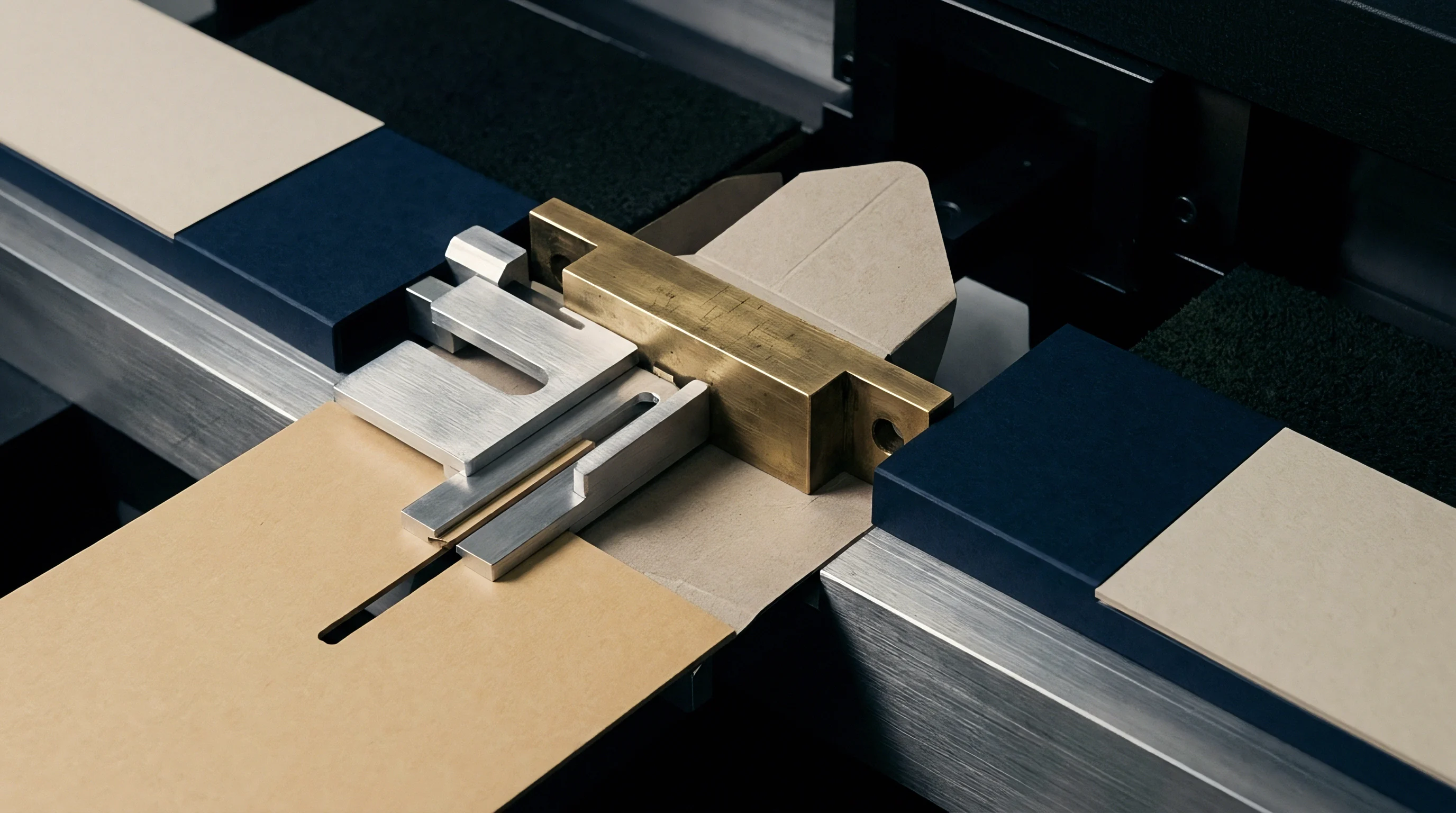

Die
Substrate performance during scoring depends heavily on internal ply bonding and surface sizing. Uncoated folding boxboard grades ~ designated under European norm DIN 19303 as UC1, UC2, or UC3 ~ present distinct mechanical challenges during die-cutting and creasing. Unlike clay-coated boards, where mineral coatings absorb and distribute localized shear forces, uncoated stocks rely entirely on raw fiber orientation, mechanical refining levels, and starch application to maintain structural integrity when shear stress initiates delamination under tool impact.

Delamination Mechanics under Rule Impact
Penetration of the steel rule forces the top liner and internal plies into Z-directional shear. In multi-ply uncoated folding boxboard, the furnish typically consists of bleached chemical pulp on the outer layers and mechanical or thermo-mechanical pulp in the middle plies. As the male creasing rule enters the sheet, material beneath the tip compresses while lower layers stretch into the female channel.
Lacking mineral protection, the stock relies on controlled delamination along inter-ply boundaries to form a clean, flexible bead. If internal ply bond strength measured via ISO 16260 exceeds mechanical thresholds, the inner layers resist shearing and transfer tensile load directly onto the outer fibers, causing visible top liner cracking along the fold axis.
Scott bond values for uncoated folding boxboard falling below 150 Joules per square metre under ISO 16260 testing indicate high risk of inner ply shear failure during scoring.

Fiber Network Response in Uncoated Grades
Sheets produced without kaolin or calcium carbonate surface coatings present higher frictional resistance against steel tooling. Uncoated fibers make direct contact with the side faces of the male rule and the entrance shoulders of the channel. Fiber length distribution across machine and cross directions dictates how the sheet yields into the tool void, while cross-direction stiffness governs crease bead form.
Uncoated virgin kraft liners offer high tensile stretch capabilities, whereas secondary fiber blends in recycled grades exhibit shorter mean fiber lengths and lower elongation limits. Sizing female channels for these substrates requires careful calibration of groove width to accommodate fiber spring-back without straining the unprinted surface sheet.
Selecting undersized female channels for uncoated boxboard leads to ruptured top liners, excessive dust generation on the blanking station, and unacceptably high folding resistance on high-speed cartoning lines.

Channel
Establishing correct groove geometry prevents top liner fracture while maintaining defined fold lines. Female creasing channels ~ whether pressboard counter strips, phenolic matrix, or steel counter plates ~ act as the receiving die for the substrate, where caliper dictates depth and rule thickness sets the baseline. For uncoated folding boxboard, calculating channel dimensions requires modified board factors compared to standard clay-coated boards to compensate for higher sheet bulk and surface roughness.
Dimensional Calculations and Board Multipliers
Mathematical formulas for matrix sizing rely on board thickness and rule width. Standard channel width calculation follows the formula where matrix width equals creasing rule thickness plus the product of substrate caliper and a board factor multiplier. For coated folding boxboard, this factor typically ranges between 1.5 and 1.7.
Uncoated folding boxboard grades demand a higher multiplier, generally between 1.7 and 1.9, owing to greater fiber friction, higher bulk ranging from 1.3 to 1.6 cubic centimetres per gram, and different elastic recovery profiles. Matrix channel depth matches or slightly exceeds board caliper, ensuring complete bead formation without crushing surrounding stock areas.
The primary variables governing female matrix dimensioning include:
- Substrate Caliper measured in micrometres according to ISO 534 testing standards under five kilopascal pressure loads.
- Creasing Rule Thickness expressed in point size or millimetres, where two-point rules equal 0.71 millimetres and three-point rules equal 1.05 millimetres.
- Board Factor Multiplier adjusted specifically for uncoated furnish compressible volume and cross-direction bending stiffness values.
- Matrix Channel Depth chosen to accommodate displaced bulk volume without creating severe shoulder impression marks on the reverse sheet side.
Higher fiber surface friction on unprinted top layers demands wider groove walls to prevent surface scuffing during penetration.

Worked Dimensioning for Four Hundred Micron Stock
Consider a converter processing a four hundred micrometre sheet on a high-speed flatbed machine. The substrate is an uncoated solid unbleached board with a bulk profile of 1.45 cubic centimetres per gram and a caliper of 0.40 millimetres. The die tooling utilizes a two-point creasing rule measuring 0.71 millimetres in width.
Applying the uncoated board factor of 1.8 to the channel width calculation yields a required channel width of 0.71 plus the product of 1.8 and 0.40, resulting in a target female channel width of 1.43 millimetres, as thicker board requires wider channels.
Matrix depth for this four hundred micrometre board defaults to 0.40 millimetres. Standard commercial matrix manufacturing supplies channels in discrete step increments. The operator selects a matrix profile measuring 0.40 millimetres in depth and 1.40 or 1.50 millimetres in width.
Selecting the 1.50 millimetre channel provides necessary safety margin against batch caliper variations across the mill run.
| Substrate Caliper (µm) | Rule Thickness (pt / mm) | Board Factor | Calculated Width (mm) | Recommended Matrix SKU (Width x Depth mm) |
|---|---|---|---|---|
| 350 | 2 pt / 0.71 mm | 1.8 | 1.34 | 1.40 x 0.35 |
| 400 | 2 pt / 0.71 mm | 1.8 | 1.43 | 1.50 x 0.40 |
| 450 | 2 pt / 0.71 mm | 1.8 | 1.52 | 1.50 x 0.45 |
| 500 | 3 pt / 1.05 mm | 1.8 | 1.95 | 2.00 x 0.50 |
| 600 | 3 pt / 1.05 mm | 1.8 | 2.13 | 2.20 x 0.60 |
| Dimensions calculated under ISO 187 standard conditioning at 23 degrees Celsius and 50 percent relative humidity using TAPPI T 411 caliper protocols. | ||||
Standard coated board matrices can perform adequately on uncoated stock if platen pressure is increased to force the crease bead into shape.
Press
Converting equipment demands accurate setup parameters to ensure uniform crease formation across the full sheet. Platen alignment governs crease symmetry. Platen pressure adjustments must remain minimal once channel profiles are installed, as excessive pressure crushes the porous structure of uncoated virgin fibers, reducing overall box compression strength.
Temperature and relative humidity within the press room alter paperboard moisture content rapidly, shifting material flexural rigidity during long manufacturing runs.

Is Phenolic Matrix Superior to PVC for Uncoated Board?
Synthetic base materials vary in deformation behavior when subjected to repeated platen impacts. Phenolic matrix channels feature high dimensional stability and hard, rigid shoulders that maintain sharp channel edges across millions of impressions. Uncoated board fibers, possessing higher abrasive surface characteristics than clay-coated sheets, wear down softer poly-vinyl chloride channel walls rapidly.
Phenolic base materials resist channel spreading. This shoulder erosion widens effective channel geometry over time, resulting in loose, poorly defined fold lines and erratic folding torque on packaging machinery.
DIN 19303 grade definitions for unbleached uncoated folding boxboard enforce a caliper tolerance of plus or minus five percent across the production reel.
Failure Modes from Incorrect Geometry
Inaccurate groove dimensioning manifests quickly on the packaging line through structural defects, as creasing parameters shift with fiber origin.
Defects observed on converting lines include:
- Top Liner Cracking resulting from narrow channel width forcing extreme tension across unprinted surface fibers during rule entrance.
- Double Crease Formation caused by excessive channel width allowing the substrate to flex in two distinct parallel lines around the rule tip.
- Reverse Side Shearing originating from over-deep matrix selection that breaks the bottom plies against channel base surfaces.
- Fluff and Dust Accumulation generated when sharp channel shoulders shear rough fiber surfaces during dynamic mechanical insertion.
Purchase specifications citing ISO 187 conditioning guidelines assign financial liability for creasing splits to the packaging buyer if pressroom relative humidity drops below forty percent during converting.


Trench
Milled steel counter plates offer an alternative to adhesive-backed resin strips for long runs. Machine-cut female grooves eliminate alignment errors inherent in individual matrix placement across multi-up die layouts. When cutting uncoated board, steel trench geometry requires precise chamfering along top entrance edges to ease fiber entry without scraping uncoated surface layers.
Counter Plate Milling and Chamfer Profiling
Machining female grooves directly into steel plates allows precise control over side-wall angles. Rectangular grooves with ninety-degree vertical walls induce sharp stress points along the crease shoulder. Tapered or trapezoidal trenches featuring an entrance chamfer angle between fifteen and thirty degrees allow smooth substrate displacement, where crease width directly affects folding torque.
Smooth transitions along the trench wall prevent fiber picking and surface abrasion, preserving the pristine raw texture characteristic of uncoated folding boxboard grades.

Standard Calibration Sequence for Production Setup
Tooling adjustment requires systematic steps on the converting floor before running high-volume jobs.
- Verify delivered substrate caliper across five test points per sheet using an ISO 534 compliant micrometer.
- Inspect steel creasing rule height and tip radius to confirm conformity with die tooling specifications.
- Clean press bed thoroughly using solvent degreasers to ensure perfect bonding for matrix locator strips or steel plates.
- Transfer matrix channels onto the counter plate under slow impression jogging cycle at minimum operating pressure.
- Peel locator carrier tape cleanly at a forty-five degree angle to avoid disturbing channel positioning.
- Execute test impressions on standard job stock and measure crease bead height using specialized optical depth gauges.
- Inspect internal ply delamination by cutting transverse cross-sections of folded creases under low-power optical magnification.
It remains uncertain whether laser-ablated counter channels can maintain consistent wall angles across high-density fiberboard backing plates during ten-million-impression production runs.


Ledger
Tooling economics depend on scrap reduction and matrix longevity during extended converting operations. Uncoated stock purchases carry lower raw material costs per tonne than multi-coated bleached boards, but converting scrap rates can eliminate these initial savings if crease parameters are sized incorrectly ~ since tooling selection drives scrap and moisture loss reduces fiber flex. Managing channel inventory based on strict technical board properties establishes predictable production yields.

Financial Consequences of Crease Defect Rates
Excessive folding torque or split top liners generate high waste volumes during automatic cartoning. Packaging lines running at speeds above five hundred cartons per minute require precise crease stiffness, as excessive depth causes liner rupture. A split crease reduces side-wall compression integrity, causing jam-ups in glue tracks and automatic cartoning feeders where die geometry governs carton squareness.
Quantifying matrix performance across long runs reveals that higher initial outlay for rigid phenolic matrix or milled steel counters pays back rapidly through reduced line downtime and eliminated customer rejects.
| Counter Matrix Technology | Expected Life (Impressions) | Channel Width Drift (µm) | Tooling Cost Ratio | Scrap Generation Rate (%) |
|---|---|---|---|---|
| Standard PVC Matrix | 50,000 | +80 | 1.0 | 2.8 |
| Premium Phenolic Matrix | 250,000 | +20 | 1.8 | 0.6 |
| Milled Steel Counter Plate | 2,000,000+ | < 5 | 8.5 | 0.2 |
Uncoated virgin fibers absorb platen compression energy differently than clay-coated mineral networks.
While narrow channels fracture top liners, a matrix channel chosen to accommodate the thickest tolerance boundary of an uncoated board lot prevents line stoppages without sacrificing crease definition.