Piezoelectric Sensor Frequency Response Calibration for Folding Boxboard Converting
Piezoelectric sensor frequency response calibration prevents amplitude distortion during high speed creasing by matching amplifier cutoff to rule strike transients.

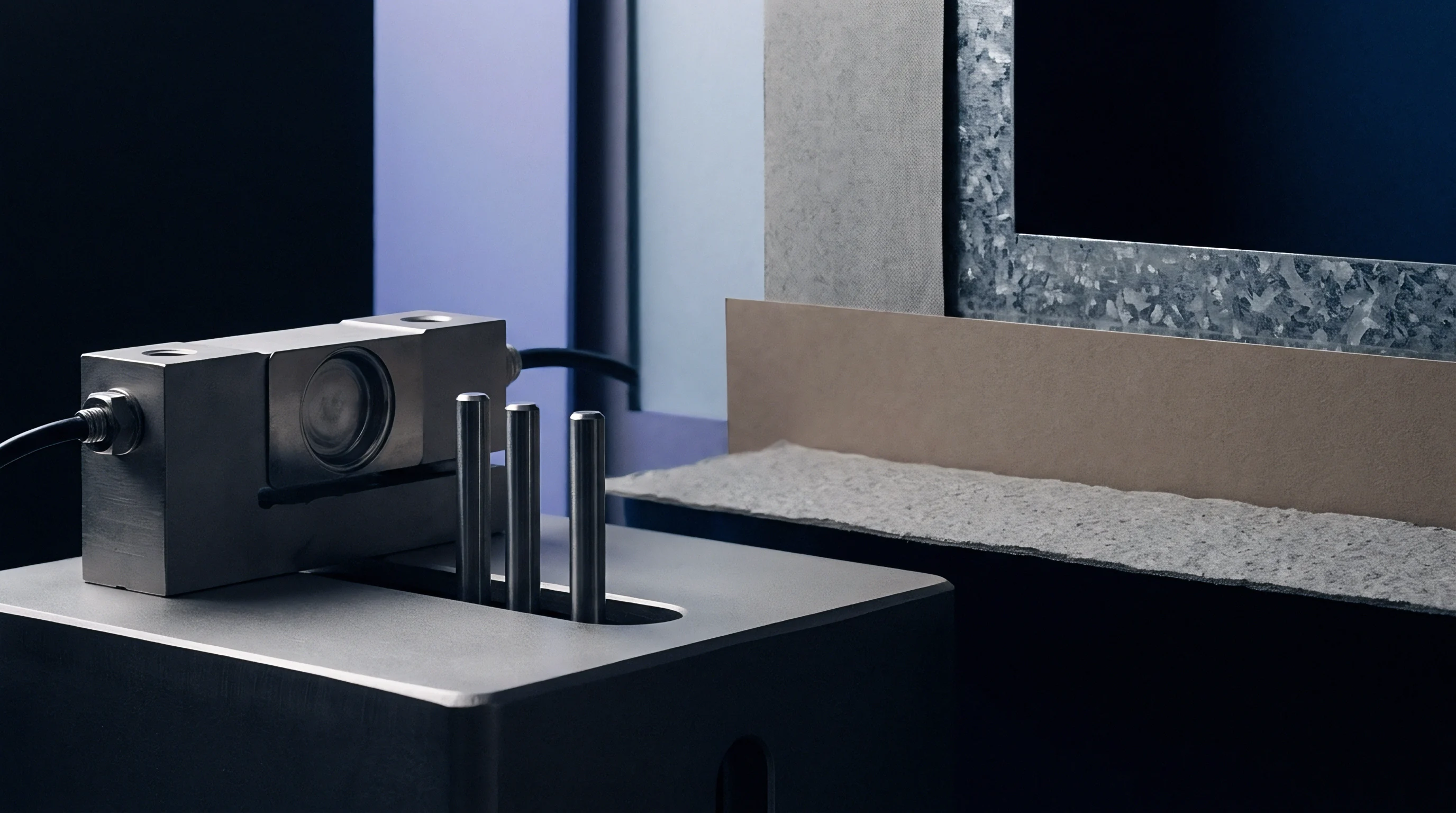
Spike
In folding boxboard packaging, high-speed flatbed die-cutting and creasing operations create sharp mechanical force pulses during impression. Converting lines running at 8,000 to 12,000 sheets per hour drive steel creasing rules into multilayered paperboard within milliseconds, with contact times dropping below two milliseconds. This rapid interaction between the steel rule, the board top liner, and the counter-crease matrix drives up contact stress at extremely high rise velocities.

Transient Force Dynamics in High Speed Converting
Rule contact with multilayered boxboard happens in tight time frames. For standard 450 g/m² folding boxboard with a caliper of 610 micrometers passing through a flatbed die at 300 impression strokes per minute, the indentation phase takes just 250 microseconds. Over this window, force climbs from zero to a peak indentation threshold of 12.5 kN per meter of crease length.
Fourier spectrum decomposition shows that this transient impulse carries critical frequency harmonics up to 12 kHz, while structural ringing in the die tool frame adds secondary acoustic spectral lines between 15 kHz and 35 kHz.
When measuring these transient events with load transducers embedded in the die backing platen, uncalibrated mechanical resonance distorts the force profile. If a sensor has a natural fundamental frequency near 20 kHz with a mechanical quality factor of 20, high-frequency harmonics from the impact trigger resonant ringing inside the crystal assembly. This produces artificial voltage overshoot, leading data acquisition systems to record peak forces up to 38 percent higher than the actual contact force.
Mechanical overshoot distorts press feedback, prompting operators to back off impression pressure, which causes incomplete crease folding and board cracking on automatic carton gluers.
ISO 16063-21 dynamic calibration standardizes secondary shock sensitivity measurements up to 10 kilohertz to prevent peak force measurement errors on high-speed impression platens.
Consider a practical converting example involving a triple-wall folding boxboard run where impression forces are monitored to control creasing matrix depth. Assume an uncalibrated load washer with a nominal static sensitivity of 4.12 pC/N sits beneath a rotary creasing anvil. During a production run at 250 meters per minute, rule impact yields a rise time of 180 microseconds, and actual peak contact force reaches 8.2 kN.
Due to undamped high-frequency resonance at 22 kHz inside the sensor housing, the output charge signal spikes to a peak corresponding to 11.3 kN. Relying on this inflated reading, the operator backs off the creasing gap by 0.08 mm. The actual force drops below the yield point of the middle mechanical pulp layer, resulting in stiff creases, flap spring-back, and automated line stoppages at the cartoning plant.
Uncorrected resonant amplification skews peak load measurements, leading to premature tooling rejection or undetected score cracking across full production runs.

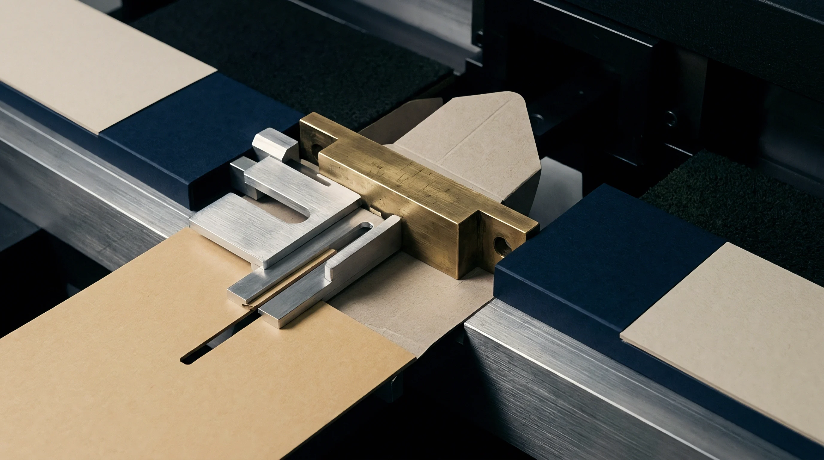
Piezo
Quartz sensors and ceramic crystalline elements supply the stiffness required to track force changes occurring on microsecond scales. Natural quartz exhibits a high stiffness modulus along its longitudinal axis, pushing fundamental resonant frequencies above 70 kHz for bare sensing disks. Crystalline quartz also maintains charge linearity over wide dynamic ranges, making it suited for impression platens subjected to cyclic impact loads up to 100 kN.

Mechanical Transducer Selection for Flatbed Dies
Solid-state sensing elements built into impression platens convert applied stress directly into electric charge. High-impedance charge mode transducers output picocoulombs per Newton straight from the synthetic crystal lattice. These signals pass through low-noise coaxial cables to an external charge amplifier, which converts charge to proportional voltage.
Low-impedance voltage mode designs place a miniature circuit inside the housing, converting charge to a low-impedance voltage signal before it leaves the sensor body. However, integrated microelectronics limit maximum operating temperatures and restrict dynamic response limits compared to pure charge-mode quartz units.
While quartz crystals offer high fundamental stiffness, lead zirconate titanate ceramics yield significantly higher charge output per unit force. This improves signal-to-noise ratios during light-impact tasks like micro-flute creasing or light embossing. On the downside, ceramic elements have lower natural resonant frequencies and suffer from higher thermal sensitivity drift as press temperatures rise over long production runs.
| Sensor Technology | Fundamental Resonance (kHz) | Dynamic Range (kN) | Charge Sensitivity (pC/N) | Thermal Drift Rate (%/10°C) |
|---|---|---|---|---|
| Quartz High-Impedance Charge Washer | 75 to 100 | 0.1 to 120 | -4.3 | 0.02 |
| PZT Ceramic Low-Impedance Voltage Mode | 35 to 50 | 0.05 to 50 | -110.0 | 0.18 |
| Piezoresistive Thick Film Element | 12 to 20 | 0.01 to 10 | N/A (mV/V) | 0.45 |
| Polyvinylidene Fluoride (PVDF) Film | 15 to 30 | 0.001 to 2 | 25.0 | 0.85 |
| Data derived from standardized impulse calibration tests at 23°C and 50% relative humidity per ISO 16063-22 protocols. | ||||
Selecting appropriate transducer configurations requires evaluating environmental and physical degradation factors on the converting floor. Dynamic measurement accuracy degrades rapidly when electrical insulation or mechanical mounting conditions deviate from standard tolerances.
- Insulation degradation across high-impedance coaxial cables permits charge leakage to ground, inducing severe low-frequency signal drift during steady press impression cycles.
- Pre-load relaxation of the mounting bolt assembly alters the mechanical transfer function, shifting the transducer fundamental resonant peak down into the measurement passband.
- Housing acoustic coupling allows structural frame vibrations from adjacent die-cutting units to contaminate primary rule contact force signals.
- Thermal shock transients generated by friction heating at high press speeds create false low-frequency baseline offsets in ceramic sensing elements.
Pre-calibrated factory sensitivity ratings rarely remain valid across die platen retrofits, as local mounting stiffness introduces unrecorded mechanical resonance shifts.

Excitation
Mapping sensor response characteristics requires precise mechanical impulse inputs applied across a broad spectrum. Calibration determines the complex transfer function linking input mechanical force to output electrical charge across magnitude and phase domains. Testing relies on controlled impact methods or continuous electrodynamic shaker excitation to evaluate sensor behavior from near static states up to 50 kHz.

Bench Setup and Impulse Testing Procedures
Laboratory verification relies on dropping hardened steel spheres onto the active face of mounted sensors. Ball-drop testing generates predictable microsecond contact pulses based on sphere mass and impact velocity. Hopkinson pressure bar testing provides pure uniaxial mechanical shock waves with rise times under 10 microseconds, allowing precise evaluation of high-frequency sensor resonance and mechanical damping factors.
A insulation resistance dropping below 10 teraohms in high-impedance charge lines causes low-frequency signal drift during continuous platen dwell cycles.

Implementation of Swept Sine Calibration Methods
Electrodynamic shakers deliver continuous harmonic acceleration across target operational frequencies. Back-to-back calibration mounts the target transducer directly onto a reference accelerometer certified to ISO 16063-21 standard specifications. Swept sine testing measures magnitude deviations and phase lag across discrete frequency steps, outputting a complete frequency response Bode plot.
- Mount the piezoelectric force sensor onto the electrodynamic shaker anvil using a calibrated torque wrench set to 2.5 Nm.
- Attach the charge amplifier input cable, verifying that total cable insulation resistance exceeds 100 teraohms using a high-voltage megohmmeter.
- Configure the signal generator to deliver a logarithmic sine sweep from 10 Hz to 50 kHz at a constant acceleration level of 50 m/s².
- Record simultaneous voltage output channels from the reference accelerometer and the target force transducer using a 24-bit high-speed digitizer sampling at 500 kHz.
- Calculate the complex transfer function by dividing output magnitude by reference input acceleration across every 10 Hz frequency bin.
Phase shift skews time domain peak alignment. ISO 16063-21 Clause 6.3 mandates continuous phase shift tracking alongside voltage magnitude measurements, altering how charge amplifier low-pass filters are tuned prior to press mounting.

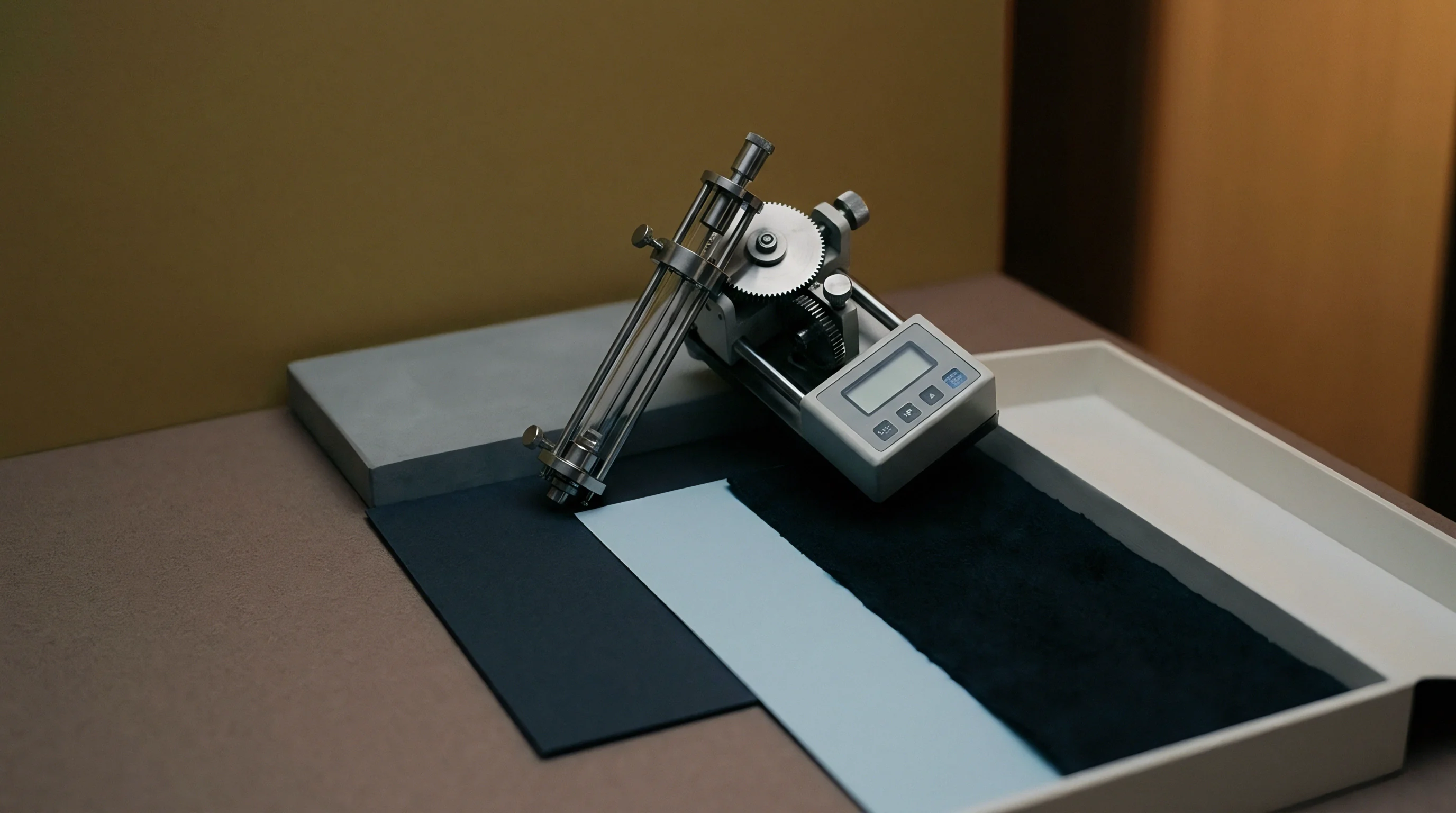
Bandwidth
Frequency measurement bounds dictate how accurately high-speed impression peaks are recorded by data acquisition hardware. Insufficient upper bandwidth attenuates sharp transient peaks, rounding off force spikes that correspond to rule penetration into boxboard liners. Excessive bandwidth captures unwanted mechanical structural noise, obscuring true board deformation mechanics with high-frequency frame ringing.

How Does Charge Amplifier Gain Affect Resonant Peaks?
Setting signal amplification ratios shifts the noise floor while influencing the high-frequency upper cutoff limit. High charge amplifier feedback capacitance lowers closed-loop system bandwidth, acting as a physical analog low-pass filter. When measuring high-speed die impression pulses with rise times under 200 microseconds, charge amplifier bandwidth must exceed 25 kHz to maintain magnitude accuracy within a 1 percent error boundary.
Bessel analog filters provide uniform group delay across their passband, preserving time-domain pulse shapes without introducing ringing artifacts. Butterworth filters maximize flat magnitude response but introduce non-linear phase shifts near the cutoff frequency, distorting peak alignment. Chebyshev filters yield sharp roll-off rates at the cost of passband ripple, making them unsuitable for precision impulse load analysis during boxboard converting.
| Filter Topology | Cutoff Frequency (kHz) | Attributed Peak Force Error (%) | Phase Delay at Peak (µs) | Ringing Artifact Amplitude (%) |
|---|---|---|---|---|
| 4-Pole Bessel | 10 | -4.2 | 32.5 | 0.0 |
| 4-Pole Bessel | 25 | -0.3 | 13.0 | 0.0 |
| 4-Pole Butterworth | 10 | +1.8 | 45.2 | 4.5 |
| 4-Pole Butterworth | 25 | +0.1 | 18.1 | 1.2 |
| 8-Pole Chebyshev | 10 | +8.5 | 82.0 | 14.2 |
| 8-Pole Chebyshev | 25 | +1.2 | 33.0 | 3.8 |
Because filter selection directly alters peak pressure values, high sampling rates are required to prevent aliasing errors. Ultimately, overall frequency response defines force reading precision, while targeted calibration curves work to eliminate mechanical ringing artifacts.
Bessel filter topologies with a four-pole response maintain uniform group delay across impression frequencies, preventing artificial peak shape distortion during crease scoring.
Implementing reliable signal conditioning circuits requires balancing amplifier gains against digitizer sampling thresholds. Operators configure hardware settings to maintain signal integrity throughout impression cycles.
- Amplifier range selection must match peak expected charge outputs without exceeding the maximum input voltage threshold of the analog-to-digital converter.
- Analog low-pass filtering must be placed prior to digital conversion to remove frequency components above half the Nyquist sampling rate.
- Group delay consistency must be verified across the working spectrum to prevent time distortion of multi-rule contact sequence signatures.
- Sampling frequency allocation must run at a minimum of ten times the highest target signal harmonic to support faithful wave reconstruction.
It remains unclear how emerging machine-learning edge processors will handle dynamic deconvolution of high-frequency die structural noise without introducing unacceptable digital processing latency into real-time press stoppage controls.

Discrepancy
Discrepancies between recorded force peaks and actual board matrix compression lead directly to score cracking. Folding boxboard structures feature mechanical pulp cores sandwiched between chemical pulp outer plies, and sound score formation relies on controlled delamination within that mechanical core under precise shear and bending forces. Board moisture also softens matrix compression resistance.
If dynamic force instruments deliver inaccurate load readings, platen settings will either split the top liner or fail to break internal bonds, yielding defective cartons.
Score line fracturing occurs when uncalibrated force monitoring fails to detect die penetration shifts exceeding fifteen micrometers in heavy board grades.

Commercial Consequences of Imperfect Force Sensing
Inaccurate load readings throw off make-ready patching decisions on the converting floor. When uncalibrated transducer resonance creates false force spikes, technicians apply paper patching tape to die backing plates to ease perceived over-impression. This adjustment reduces local penetration below tolerance, producing boxes that burst open on high-speed packing lines.
Rejecting a 50-tonne run of 350 g/m² coated boxboard at $1,350 per tonne results in $67,500 in direct material losses, while unscheduled press downtime adds cost penalties averaging $480 per hour.

Verification Steps for Converting Floor Compliance
Audit procedures require scheduled drop-ball shock tests to check for sensor calibration drift. Plants verify force measurement loops every six months by mounting portable shock reference units directly to die impression platens. Comparing peak charge outputs against standard calibration dossiers ensures signal conditioning channels keep magnitude errors below 1.5 percent.
A calibrated sensor channel pays for itself during the initial make-ready shift by preventing unnecessary rule height grinding.