Creasing Rule Selection for Coated Folding Boxboard Conversion
Selecting steel creasing rules and matrix channels for coated FBB requires matching board caliper and CTMP core shear limits to prevent surface cracking.

Ply
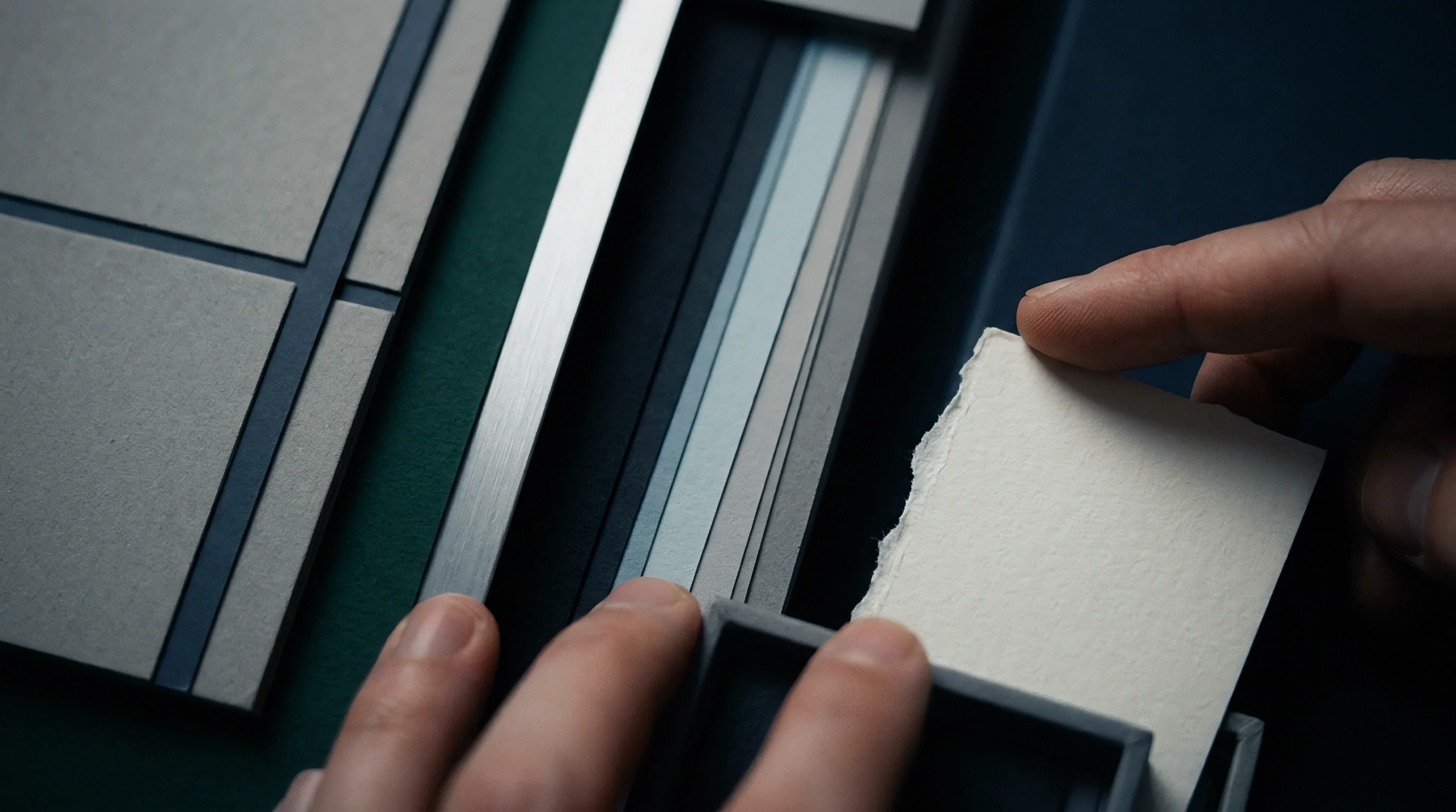
Multi-layered paperboard substrates combine distinct pulp formulations across their cross-section to balance flexural rigidity against surface printability. Coated Folding Boxboard ~ classified commercially as GC1 or GC2 ~ depends directly on this structured arrangement. Its top layer consists of fully bleached chemical pulp finished with 15 to 30 grams per square meter of mineral coating containing calcium carbonate, kaolin clay, and synthetic latex binders.
Beneath that printable surface sits a thick middle core composed mainly of mechanical pulp like Chem-Thermo-Mechanical Pulp or Groundwood. The reverse liner uses either a thin bleached chemical sheet on GC1 grades or an unbleached or semi-bleached chemical sheet on GC2 variants. Because of this internal layout, boxboard responds to creasing forces quite differently than solid bleached sulfate or recycled containerboard grades.
Layered Furnish Dynamics under Localized Load
Structural boxboard grades sandwich a mechanical fiber core between chemical pulp liners to maximize sheet caliper at low grammage, yielding a high moment of inertia. When a creasing rule depresses the sheet into a female die channel, the dynamic goes beyond basic embossing or geometric bending. Effective creasing relies on controlled internal ply separation.
Because the mechanical pulp core offers far lower interlaminar shear strength than the tough chemical outer plies, vertical indentation concentrates shear stress directly across the middle of the sheet. Short, stiff mechanical fibers then slip and delaminate along horizontal micro-planes, forming a flexible internal hinge.
When the score blade strikes, fibers ought to slip apart cleanly. If internal delamination fails during rule penetration, the outer chemical plies and mineral coating absorb the entire bending strain when the board folds to 90 or 180 degrees. Over-strained mineral coatings fracture, exposing raw fiber and leaving visible cracking along package edges.
Conversely, an overly weak middle core collapses completely, sacrificing structural spring-back and causing bulging crease lines that jam high-speed erecting machinery. How GC1 and GC2 board behaves under creasing rules depends heavily on core moisture content and fiber bonding density in the CTMP core, evaluated under ISO 187 conditioning standards at 23 degrees Celsius and 50 percent relative humidity.
Mechanical pulp middle plies conditioned at 23 C and 50 percent relative humidity achieve shear delamination at a score bending moment reduction exceeding 55 percent compared to uncreased FBB board.
Outer coating layers bring their own mechanical limits to the scoring process. The mineral coating matrix has low elongation at break, typically failing once local tensile strain exceeds 1.2 to 1.8 percent. Creasing rule profile design must limit surface tensile strain while delivering enough vertical force to shear the core.
Increasing top-ply coat weight without bumping binder levels reduces this allowable elongation threshold, accelerating surface rupture along cross-direction crease lines.
Mechanics of Shear Delamination in CTMP Cores
Downward force from a steel creasing blade makes internal fibers yield along horizontal planes. This yield mechanism absorbs energy and forms an internal crease bead ~ often called the male crease bulge ~ on the reverse side of the board. The width and height of this bead dictate how much bending stiffness the crease line loses.
According to DIN 55437 crease testing procedures, optimal converting requires a 40 percent to 60 percent reduction in bending moment relative to uncreased paperboard. Hitting that target without cracking the top coating requires precise coordination between rule thickness, penetration depth, and female counter-die channel geometry.
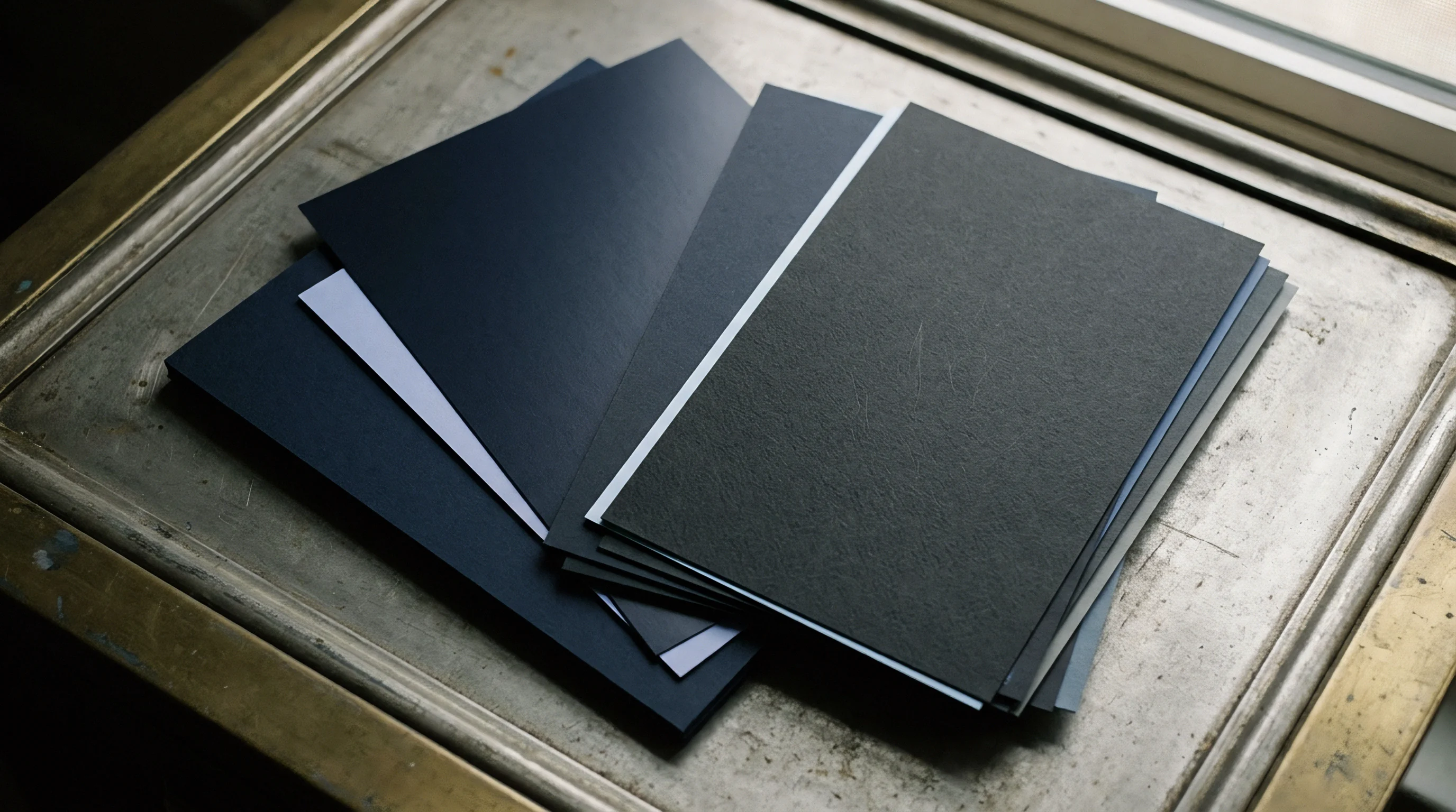
The core yields in shear first. How much the mechanical core resists interlaminar shearing determines the force needed to form the bead. Chemical pulp plies have high internal bond strength ~ measured by Z-direction tensile testing under ISO 15754, often exceeding 300 kilopascals.
CTMP cores show Z-tensile values between 120 and 180 kilopascals. This lower bonding energy allows micro-delamination under localized shear stress without destroying the continuous tensile capacity of the outer liners. Running stock with elevated moisture levels softens the mechanical core too much, muddying crease definition and throwing off carton squareness during gluing.
Fiber alignment relative to machine direction alters delamination geometry. Machine Direction fibers line up parallel to web flow, offering high tensile strength but lower cross-web shear resistance. Cross Direction fibers lie transverse to web travel and present higher flexural resistance during scoring.
Choosing creasing rules for Cross Direction scores requires extra care regarding top-coat cracking risks, since the rule has to bend stiffer fiber bundles across their longitudinal axis. Proper rule selection balances these anisotropic properties against the specific grammage and caliper of the GC1 or GC2 grade.
Uncoated reverse sides on GC2 boards add another friction dynamic during matrix engagement. Rougher surfaces on mechanical or unbleached liners change how the sheet slides into the female matrix channel on initial blade impact. Lower surface slip pulls the material into pure tension earlier in the stroke.
If matrix chamfers lack adequate radius polishing, the failure mode shifts from internal core shear straight to top-coat tensile fracture.
Delamination depth needs to extend across at least three distinct internal planes in the CTMP core to form a true mechanical hinge. Partial delamination along a single plane leaves residual bending stiffness too high, making folder-gluer belts skew blanks during fast production runs. On the other extreme, completely crushing the core destroys structural integrity, producing soft, floppy edges that fail stack-loading compression tests in storage.
Board thickness governs how the core fails. Heavy-caliper FBB grades, from 450 to 650 micrometers, contain dense CTMP layers that need a wider stress distribution to initiate clean shear. Thinner boards, between 280 and 380 micrometers, have narrow mechanical cores where over-penetration can easily cut straight through to the reverse liner.
Matching steel rule geometry to specific furnish callouts protects outer plies while driving controlled shear through the middle of the core.
Correct rule selection is the primary defense against convertibility failures on coated boxboard lines. Matching rule profile to furnish elasticity lets plants run at maximum die-cutter speeds without sacrificing carton strength.

Bevel
Steel strip dimensions and apex tip profiles control how localized compression transfers into the top coating during die-cutting. Creasing rules are made from cold-rolled hardened steel strips in standard point thicknesses: 1.5 Point, 2 Point, 3 Point, 4 Point, and 6 Point (where 1 Point equals 0.356 millimeters or 0.014 inches). For converting coated folding boxboard, 2 Point rules at 0.71 millimeters thick and 3 Point rules at 1.05 millimeters form the main shop standard.
Tip geometries range from full round and flat top profiles to center bevel and side bevel designs built for tight clearance setups.

Creasing Strip Geometry and Radius Profile Options
Choosing rule width means balancing board caliper against the blank’s required folding resistance. For FBB calipers under 400 micrometers, a 2 Point rule provides enough displacement to start internal delamination without over-stretching the coating. Calipers over 400 micrometers call for 3 Point or 4 Point rules to spread vertical force across a wider contact patch, keeping the rule tip from acting like a cutting edge.
Tip radius geometry changes stress distribution directly: a full round tip has a radius equal to half the rule thickness, so on a 2 Point rule, a 0.35 millimeter radius creates a smooth pressure gradient that shields brittle kaolin clay coatings from early shear failure.
Flat top rules put dual sharp shoulders along the blade edges. These shoulders concentrate vertical force down two parallel lines, starting dual shear planes inside the mechanical core. While flat top rules lower folding resistance on heavy grades, they sharply increase top-coat cracking risks on coated GC1 substrates if die registration strays by even 0.05 millimeters.
Center bevel rules use symmetric side angles leading to a crowned apex, driving force straight down the vertical axis. Side bevel rules push the apex to one side, which helps when scoring right next to cutting knives with limited die board clearance.
Setting rule height is the foundation of press make-ready. Standard European flatbed steel cutting rules operate at a nominal height of 23.80 millimeters or 0.937 inches. Creasing rule height has to sit below cutting rule height by an amount equal to or slightly greater than compressed board caliper.
The height differential is calculated as cutting rule height minus board caliper plus a compression factor. If the creasing rule is too tall, it cuts board along the score line; if it’s too short, it fails to trigger core delamination.
Rule bevel selection also depends on steel hardness. Standard creasing rules rate between 35 and 42 Rockwell C. Hardened-top rules reach over 50 Rockwell C to resist wear from abrasive recycled fibers or heavily filled coatings. The tradeoff is that harder steel tips deform less under impact, sending higher peak shock loads into the board surface during high-speed platen contact.
Dimensional Specifications across Machine Orientation
Because fiber alignment during web forming is anisotropic, running-direction fiber alignment exhibits double the bending stiffness of the transverse axis. Scores parallel to the Machine Direction bend fibers along their natural orientation, requiring less shear displacement to reach a ninety-degree fold. Cross Direction scores force fibers to bend across their length, creating higher mechanical resistance.
Converting engineers often specify slightly wider rule profiles or greater crease depth allowances on Cross Direction scores so all carton panels yield equal folding torque.
Clearance around adjacent features dictates score quality. When creasing rules run close and parallel to cut edges or structural slits, standard symmetrical rules displace material sideways into the open cut zone, distorting the blank. Off-center bevel rules redirect internal material displacement back toward the solid panel interior, preserving panel dimensions and stopping edge flare on folder-gluer transfer belts.
Standard creasing rule specifications, tip geometries, and recommended application limits for coated folding boxboard substrates balance these mechanical factors across common board calipers:
| Rule Thickness (Pt / mm) | Tip Profile Type | Tip Radius (mm) | Target Caliper Range (µm) | Primary Orientation Application |
|---|---|---|---|---|
| 1.5 Pt / 0.53 mm | Full Round | 0.26 mm | 200 ~ 300 µm | Machine Direction / Narrow Flap |
| 2.0 Pt / 0.71 mm | Full Round | 0.35 mm | 300 ~ 450 µm | General GC1 & GC2 Standard Lines |
| 2.0 Pt / 0.71 mm | Double Bevel / Flat | 0.18 mm shoulder | 350 ~ 500 µm | Cross Direction Heavy Crease |
| 3.0 Pt / 1.05 mm | Full Round | 0.52 mm | 450 ~ 600 µm | Heavyweight GC2 Packaging |
| 4.0 Pt / 1.42 mm | Crown / Special Radius | 0.71 mm | 600 ~ 800 µm | Large Format Outer Cases & Displays |
Setting up creasing rules without evaluating board properties causes predictable converting defects. Common physical failure mechanisms triggered by poor rule thickness or profile choices include:
- Top Coating Fracturing occurs when sharp rule radii or narrow rule thicknesses exceed the maximum allowable tensile strain of the mineral coat layer along the crease crown.
- Liner Splitting develops when high vertical force combined with excessive rule height cuts through the reverse chemical pulp liner instead of generating internal core shear.
- Crease Roll-Over appears when asymmetrical rule bevels or loose die channels allow the scoring blade to deflect laterally during platen impact, producing an offset, curved score line.
- Inadequate Stiffness Reduction results from undersized rule thickness failing to displace enough CTMP core volume, leaving high residual bending torque that distorts erected carton walls.
- Board Delamination Shear Flash occurs when overly wide rule profiles crush the board matrix flat, forcing internal plies to separate beyond the score shoulder into the main panel.
Compliance with DIN 55437 crease testing prevents creasing rule depth drift from triggering score cracking penalties during high-speed carton erecting.
Rule bevel angles also drive press tonnage requirements. Broader bevel profiles spread press impact force across more surface area, raising the overall platen tonnage needed to reach target penetration across a full die layout. On high-cavity dies with over 100 lineal meters of scoring rule, picking 3 Point rules instead of 2 Point rules can raise impression tonnage by 25 to 35 percent, accelerating platen wear and flexing the die board.
Converter setup sheets should specify exact rule part numbers, steel hardness ratings, and apex radii instead of generic point sizes. Leaving profile selection to die-room discretion invites lot-to-lot variance on standard packaging runs.
Mismatched rule profiles degrade carton squareness, boost folder-gluer reject rates, and lead to direct financial claims over damaged packaging lots.


Channel
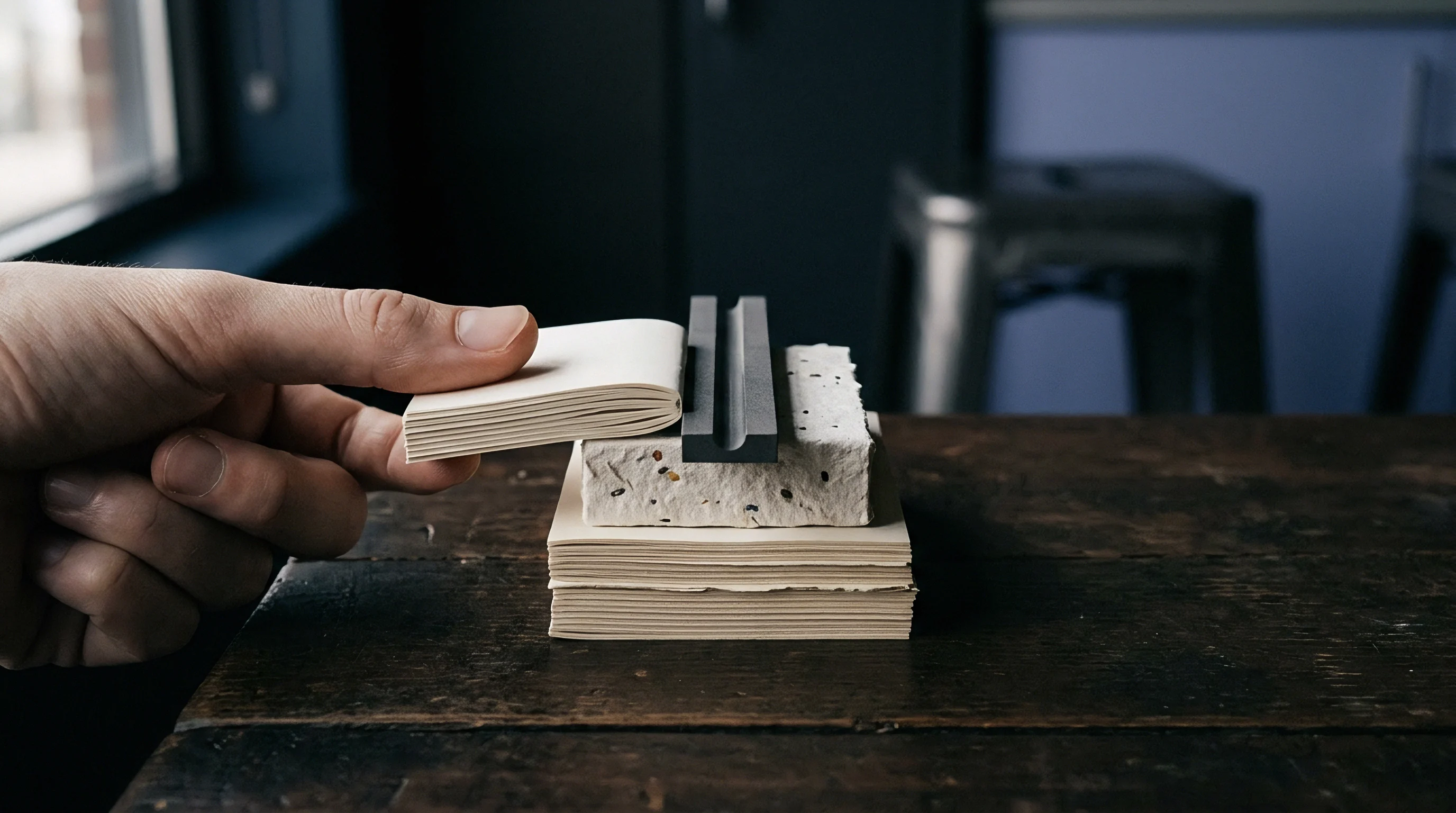
Female counter-die grooves establish the boundary into which displaced paperboard fibers expand under scoring force. The matrix channel dictates both width and depth of the reverse male bead. Modern converting uses self-adhesive channel matrix strips mounted to steel platen plates or custom CNC-milled steel counter-plates.
Channel geometry has to provide enough volume for the displaced board bulk without pinching and crushing the shoulders of the crease line.
Counter Die Dimensioning Mechanics for Coated Boxboard
Sizing female grooves requires accurate board thickness measurements alongside known paperboard density factors. Matrix channel width calculations for coated folding boxboard differ considerably from those for solid bleached sulfate or corrugated medium. The standard formula for FBB channel width is rule thickness plus 1.5 to 1.7 times board caliper.
For GC1 and GC2 grades with bulk-dense CTMP cores, a factor of 1.5 applies to calipers under 400 micrometers, increasing to 1.7 for calipers between 400 and 650 micrometers.
For example, with a 400 micrometer (0.40 millimeter) caliper FBB and a 2 Point (0.71 millimeter) creasing rule, channel width equals 0.71 millimeters plus 1.5 times 0.40 millimeters, giving a target width of 1.31 millimeters. Channel depth matches nominal board caliper ~ so a 0.40 millimeter board calls for a 0.40 millimeter depth. A shallower channel restricts bead formation, squeezing material sideways and increasing coating strain.
An oversized channel depth stops the rule tip from properly compressing the core against the bottom of the groove, leaving soft, poorly defined score lines.
Matrix channel walls need chamfered entry angles. Smooth shoulder radii on channel edges stop the reverse liner from shearing sharply as it’s pulled down into the groove. Polymeric channels come molded with smooth entry curves; pressboard channels require manual bevel sanding or milled chamfers to avoid tearing unbleached reverse fibers during continuous high-speed runs.
Engineered matrix dimensioning guidelines cover standard coated folding boxboard caliper ranges when using 2 Point and 3 Point steel creasing rules:
| Board Caliper (µm) | Grammage Basis (g/m²) | Rule Thickness (Pt / mm) | Calculated Channel Width (mm) | Specified Channel Depth (mm) |
|---|---|---|---|---|
| 300 µm | 215 g/m² | 2.0 Pt / 0.71 mm | 1.16 mm | 0.30 mm |
| 350 µm | 245 g/m² | 2.0 Pt / 0.71 mm | 1.235 mm | 0.35 mm |
| 400 µm | 275 g/m² | 2.0 Pt / 0.71 mm | 1.31 mm | 0.40 mm |
| 450 µm | 310 g/m² | 2.0 Pt / 0.71 mm | 1.43 mm | 0.45 mm |
| 500 µm | 345 g/m² | 3.0 Pt / 1.05 mm | 1.80 mm | 0.50 mm |
| 600 µm | 415 g/m² | 3.0 Pt / 1.05 mm | 2.07 mm | 0.60 mm |
Which Counter-Die Material Holds Dimensional Stability under Ambient Humidity Variations?
Polymer-based matrix strips swell and shift when pressroom temperature and humidity fluctuate. Phenolic resin compounds reinforced with vulcanized synthetic bases hold tight dimensional stability, maintaining channel width within 0.01 millimeters across temperature swings from 18 to 35 degrees Celsius. In contrast, pressboard matrix strips made from compressed paper layers absorb moisture in non-conditioned plants, swelling in thickness and narrowing channel width during humid shifts.
Milled steel counter-plates offer complete dimensional rigidity for runs exceeding 100,000 sheets. CNC engraving grooves directly into a hardened steel plate eliminates tape creep and channel wall breakdown. Steel counter-plates also allow precise radius contouring at the bottom of channels, optimizing bead geometry for complex automated packaging.
Proper installation of matrix channels onto the die-cutter cutting plate follows a strict mechanical sequence to achieve exact axial alignment with the upper creasing rules:
- Clean the ground steel cutting plate thoroughly using fast-evaporating solvent degreasers to remove oil residues, anti-setoff powders, and adhesive traces.
- Cut individual matrix strips to match creasing rule layout segments, ensuring a 1.0 millimeter gap remains before adjacent cutting knife intersections to prevent ejection rubber pinching.
- Locate the matrix channel onto the corresponding upper creasing rule using the locator plastic bridge profile supplied with the matrix strip.
- Peel off the protective adhesive release paper to expose the pressure-sensitive adhesive layer along the matrix underside base.
- Inch the flatbed cutting press slowly through one full cycle under light impression pressure to press the matrix base firmly onto the lower steel plate.
- Remove the plastic locator bridges carefully by pulling vertically away from the plate, leaving the matrix walls firmly bonded in perfect registration with upper rules.
- File smooth chamfers on all channel ends and apply edge-sealing tape along matrix shoulders to prevent board edge catching during high-speed sheet transport.
Softer phenolic channel counter-plates preserve matrix shoulder profile integrity when converter humidity shifts across seasonal operational shifts.
Tooling alignment determines score consistency across the sheet. A side registration error as small as 0.08 millimeters between rule apex and channel center line forces the board to shear unevenly. That unbalanced shear creates an asymmetric crease bead, making folded carton panels fishtail through high-speed folder-gluers.
When matrix shoulders wear round on long runs, material slips early during compression, causing score stiffness to drift across the production batch.
Creasing defects often stem from worn matrix channel walls rather than unexpected shifts in mill board density.
Penetration
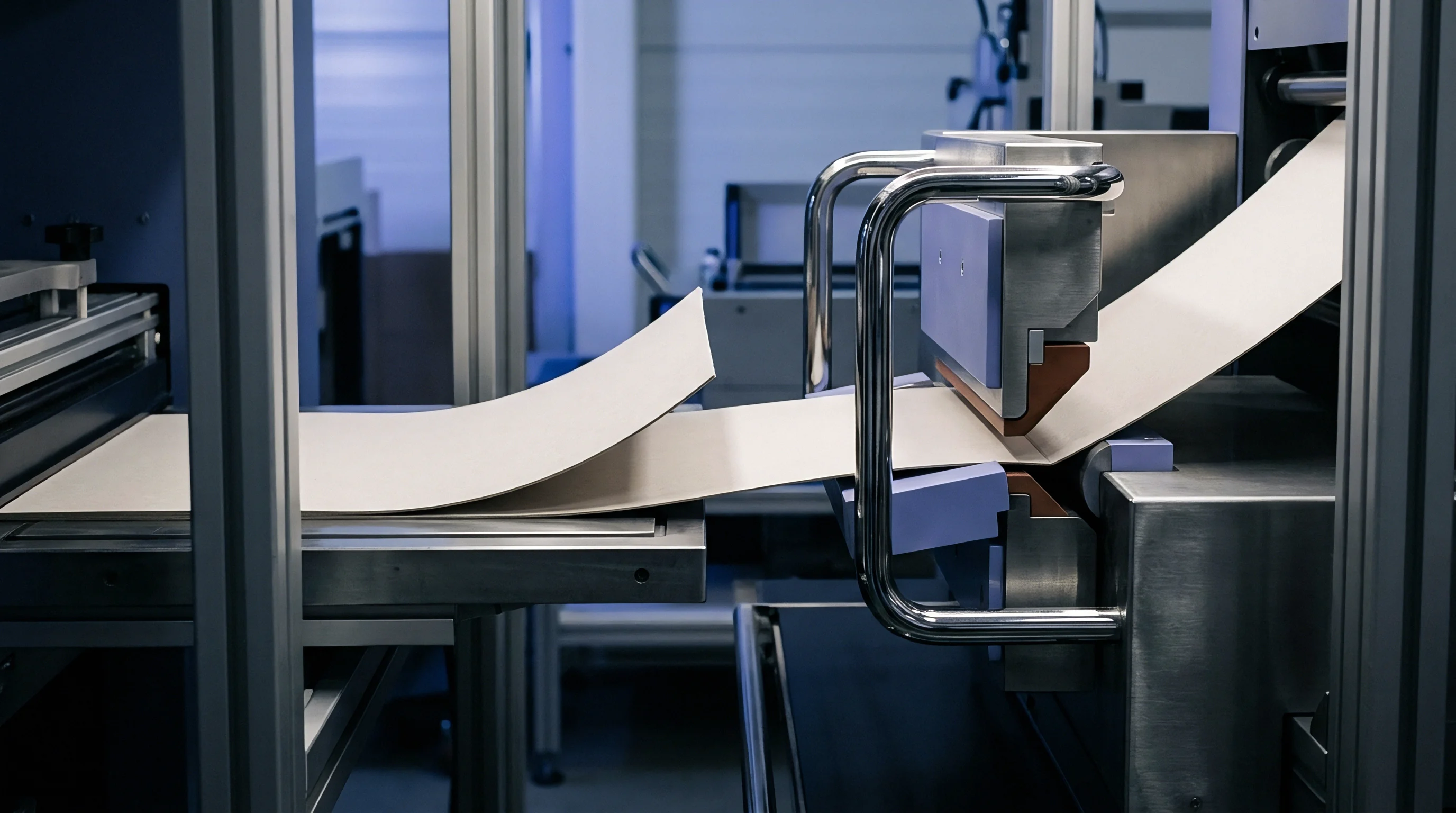
The downward stroke of the upper die board drives steel scoring strips into the sheet until reaching target depth. Penetration depth is the net vertical stroke of the rule into board thickness relative to the matrix channel plane. Operators control depth using make-ready paper behind the cutting plate, platen pressure adjustments, and rule height selection.
Indentation force has to crush the internal CTMP core adequately without slicing the reverse liner or cracking the top mineral coating.
Indentation Depth Dynamics and Bending Moment Reduction
Measuring the force needed to fold a crease to ninety degrees shows whether internal shearing actually took place. Bending stiffness testing ~ using tools like the L&W Crease Monitor or Marbach Creaseability Tester under DIN 55437 ~ quantifies score quality using the crease moment reduction ratio, or b-value. The b-value expresses creased folding resistance as a percentage of uncreased stiffness.
For instance, an uncreased FBB board with a bending moment of 100 millinewton-meters that drops to 45 millinewton-meters after scoring has a b-value of 45 percent.
High-speed automatic filling lines require b-values between 35 percent and 50 percent. Values over 60 percent point to under-penetration or an undersized rule profile, leaving behind residual stiffness that bows carton panels and jams erecting machines. Values under 30 percent signal over-penetration or channel crushing, destroying hinge stability and leaving soft, floppy corners that collapse under stack loads.
Calculating penetration depth combines board caliper, rule height differential, and make-ready sheet thickness. Target penetration usually lands between 60 percent and 75 percent of nominal board caliper. On a 400 micrometer board, the rule tip displaces the sheet into the channel by 240 to 300 micrometers.
Press operators fine-tune impression pressure in 0.01 millimeter steps, taping precision make-ready tissue behind the die plate to dial in depth across all cavities.
Press vibration shifts registration over time. Pressure variations across large platens mean center cavities take higher effective penetration than perimeter positions. Make-ready zoning compensates for this platen flexure to keep crease depth uniform across the layout.

Moisture Conditioning Effects on Crease Resistance
Equilibrium moisture in paperboard fibers directly controls ply flexibility and matrix expansion during fast scoring. Board stored in unconditioned ambient warehouses gains or loses moisture quickly as ambient humidity shifts. Standard lab conditioning under ISO 187 specifies 23 degrees Celsius and 50 percent relative humidity, yielding an equilibrium moisture content of 6.5 percent to 8.5 percent in standard FBB grades.
When relative humidity falls below 40 percent, fibers lose plasticizing moisture. The CTMP core stiffens, raising internal shear resistance. Hardened fibers resist micro-delamination, transferring scoring stress straight to the brittle top coating.
Unconditioned dry stock run in winter pressrooms suffers widespread top-coat cracking along Cross Direction scores unless operators step up to thicker rules or mist the web with moisture before die-cutting.
High humidity above 65 percent creates the opposite problem. Excess moisture weakens hydrogen bonding within mechanical and chemical plies, dropping Z-direction tensile strength. The board delaminates too easily under rule contact, forming wide, shallow, ill-defined crease beads with no spring-back.
Moisture-softened scores lose dimensional memory, springing open after gluing and causing misfeeds on automated packaging lines.
Key verification steps for converting engineers evaluating creasing penetration setup on coated folding boxboard runs include:
- Verify Substrate Moisture State prior to press make-ready using calibrated capacitive moisture meters to ensure board content falls between 6.5 and 8.5 percent.
- Calculate Baseline Penetration Depth using measured sheet caliper rather than nominal swatch book callouts to account for mill lot thickness variations.
- Perform L&W Crease Resistance Testing on first-off press blanks to confirm b-value ratios fall strictly within the 35 to 50 percent target window.
- Inspect Reverse Liner Integrity under 10x optical magnification to ensure matrix channel edges have not scored or cut unbleached chemical fibers.
- Audit Platen Impression Balance across all four die corners using carbon pressure impression film to correct for mechanical die-board tilt or press wear.
- Check Cross-Direction Score Symmetry to confirm male crease beads center perfectly within female channel walls without lateral registration drift.
Selecting narrow rule bevels on heavy caliper FBB concentrates vertical force and tears top coating layers during female channel engagement.
Caliper drift across mill production reels introduces variance during long converting runs. A basis weight tolerance of plus or minus 3 percent on a 400 micrometer board causes up to a 12 micrometer caliper swing in a single batch. When thick zones hit the die-cutter, effective penetration increases automatically, raising top-coat cracking risk.
When thin zones enter, penetration drops and score stiffness spikes. Mill specifications need tight caliper windows to maintain process capability.
Speed drives throughput, but impacts mechanics. Modern flatbed die-cutters running at 9,000 sheets per hour feature impression dwell times under 15 milliseconds per stroke. Under dynamic high-speed impact, paperboard plies behave stiffer than during static bench testing, requiring slightly deeper rule penetration in full production than initial slow-speed setup trials indicate.
How far can board suppliers narrow middle-ply density ranges before mill production costs exceed the converting scrap savings gained on high-speed packaging lines?

Outlay
Capital spending on press tooling shapes both upfront setup expenses and long-term running efficiency across high-volume boxboard jobs. Tooling economics extend well beyond the initial price of steel rules and counter-dies. Total conversion costs incorporate make-ready labor rates, press downtime, matrix wear cycles, folder-gluer waste, and customer rejection risks.
Choosing the right creasing hardware means balancing initial tooling costs against landed cost per thousand finished cartons.
Make Ready Tooling Economics across Production Volumes
Choosing self-adhesive matrix channels versus custom CNC-milled steel counter-plates sets the baseline prep cost for a job. Polymer matrix channels carry low upfront costs, around 1.50 to 3.00 USD per meter of creasing line. Installing strips manually on a 50-up packaging die board takes roughly 45 to 60 minutes of press operator make-ready time.
For short runs between 5,000 and 25,000 sheets, self-adhesive channels offer the lowest overall preparation outlay.
Milled steel counter-plates require higher upfront capital ~ ranging from 450 to 1,200 USD per die set depending on sheet format and cavity density. But steel plates cut press installation time down to under 10 minutes because the pre-milled plate mounts straight onto the platen with mechanical register pins. For repeat orders or jobs over 100,000 sheets, fast setup and zero matrix wear quickly offset the higher plate cost.
Tooling selection parameters, set-up times, and landed converting expenses vary across job run sizes:
| Tooling Option | Initial Material Cost (USD) | Press Make-Ready Time (min) | Maximum Service Life (sheets) | Tooling Cost per 10k Sheets (USD) |
|---|---|---|---|---|
| Standard Pressboard Matrix | 45 ~ 75 USD | 60 min | 35,000 sheets | 15.00 USD |
| Reinforced Phenolic Matrix | 90 ~ 150 USD | 45 min | 75,000 sheets | 12.00 USD |
| Segmented Elastomeric Matrix | 120 ~ 200 USD | 40 min | 100,000 sheets | 10.00 USD |
| CNC Milled Steel Counter-Plate | 500 ~ 1,100 USD | 8 min | 1,500,000 sheets | 3.50 USD |

Converting Speed Limits and Folder Gluer Downtime Costs
Running flatbed die-cutters at top speed creates heavy vibration that degrades score quality if channel walls flex. When matrix shoulders degrade mid-run, operators have to slow the press to prevent blank jams at ejection. Dropping a platen press from 8,500 sheets per hour down to 6,000 sheets per hour increases hourly operating overhead by 30 percent, wiping out profit margins on tight contracts.
Catching crease defects late at the folder-gluer stage drains operating margin through massive downtime and scrap losses. If score lines crack during high-speed folding, whole production lots end up quarantined. Sorting or re-running defective cartons generates scrap, eats up press capacity, and threatens delivery dates for retail launches.
Across multi-plant converting facilities, creasing defects account for over 40 percent of total folder-gluer waste on coated boxboard lines. Standardizing matrix dimensions and setting strict rule selection specifications reduced scrap rates from 2.8 percent down to 0.6 percent on high-volume GC1 pharmaceutical runs.
Customer line claims carry the biggest financial risk. High-speed cartoning equipment in pharmaceutical or food plants runs up to 400 cartons per minute. Soft, poorly creased blanks misfeed at the erecting station, triggering automatic line stops that cost end-users thousands of dollars per hour in lost output.
Standard quality agreements include explicit penalty clauses for out-of-spec score stiffness that exceeds agreed b-value tolerances.
Buying cheap rules or reusing worn matrix channels to shave small tooling expenses remains a primary cause of converting failure. Modern packaging operations require treating creasing rules and counter-plates as precision mechanical tooling designed to safeguard substrate performance.
Commercial contracts specify that creased board shipped to automated filling plants must conform to ISO 5628 stiffness standards and DIN 55437 score metrics ~ shifting all downtime liability straight to the converter if cracking or erecting jams happen.