Polymer Film Pinholing Mechanics across Creased Recycled Fiber Furnishes under Dynamic Converting Stresses
Polymer film pinholing across creased recycled stock stems from hornified fiber end punctures under high dynamic strain rates during package converting.
Matrix
Recycled pulp blends alter internal fiber distribution, density profiles, and the overall mechanical response of paperboard during converting. Secondary fibers recovered from old corrugated containers or mixed sorted graphics lose structural integrity through repeated rewetting, pressing, and drying cycles. Hornification contracts the cell walls, reducing both specific surface area and swelling capacity during water uptake.
Virgin softwood kraft fibers measuring 2.8 to 3.4 mm typically fragment down to 1.1 to 1.4 mm averages after four to six recycles. This loss in weighted average fiber length, tracked under ISO 16065-1, fundamentally alters how the fibrous matrix sheds stress under localized mechanical loading.
Fines in secondary furnishes often exceed 22 percent by weight, compared to less than 6 percent in virgin softwood sheets. These fine fragments settle into inter-fiber voids, creating dense localized zones right beside porous patches that flank stiff, unrefined fiber bundles. Shives, residual adhesives, kaolin, and calcium carbonate agglomerates accumulate in recycled stock.
When paperboard is run through smooth calendering rolls to reach a uniform caliper, these inclusions resist compaction and emerge as micro-protrusions across the sheet face. Parker Print-Surf testing under ISO 8791-4 at 1000 kPa clamp pressure shows surface roughness between 4.2 and 6.8 μm for 100 percent recycled linerboard, whereas virgin bleached kraft of identical basis weight sits between 1.8 and 2.5 μm.
Secondary Fiber Hornification and Microstructural Density
Cellulose microfibrils in secondary stock establish tight intra-fiber hydrogen bonds on initial drying, resisting rehydration during repulping. The fiber wall turns rigid, forming a stiff tube that conforms poorly during sheet consolidation. In a headbox running at 0.5 to 0.9 percent consistency, hornified fibers clump into irregular flocs under hydrodynamic shear.
The resulting web shows basis-weight swings of up to plus or minus 8 percent across micro-spans of 2 to 5 mm, plainly visible via beta-radiography or high-resolution X-ray computed tomography.
These density variations provide uneven support for applied barrier films. Liquid polymer melts and aqueous dispersions wick into low-density surface voids while leaving thin coverage over proud, hornified knots. The structural integrity of the paperboard substrate dictates how thin an applied film can remain without contacting sharp surface topography.
Uncoated recycled substrates with bulk values over 1.4 cm³/g, calculated via ISO 534, carry high surface void volumes that demand elevated coat weights to establish a continuous barrier film.
| Furnish Blend Composition | Weighted Avg Length (mm) | Fines Content (% w/w) | Shive Count (No./kg) | PPS Roughness 1 MPa (μm) | TEA MD (J/m²) | Elastic Modulus CD (GPa) |
|---|---|---|---|---|---|---|
| 100% Virgin Bleached Softwood Kraft | 2.85 | 4.2 | 12 | 2.10 | 112 | 3.45 |
| 70% Virgin Kraft / 30% Recycled OCC | 2.20 | 9.8 | 140 | 3.15 | 88 | 2.90 |
| 30% Virgin Kraft / 70% Recycled OCC | 1.65 | 16.4 | 420 | 4.80 | 64 | 2.35 |
| 100% Recycled Mixed Deinked Stock | 1.25 | 23.5 | 890 | 6.25 | 42 | 1.80 |
| Testing executed per ISO 16065-1 for fiber length, ISO 5350-2 for shive count, ISO 8791-4 for PPS roughness, and ISO 1924-3 for tensile energy absorption. | ||||||
Inclusion Agglomerates and Surface Topography Crevices
Contaminants that slip through screening and cleaning inject particulate matter directly into the web. Macro-stickies from hot-melts and pressure-sensitive labels survive as deformable synthetic bodies 100 to 500 μm across. In drying sections operating between 110°C and 140°C, these tacky polymers press out into disk-shaped inclusions embedded in the upper plies.
As they cool, their thermal contraction outpaces the surrounding cellulose, opening micro-gaps right along the particle boundary.
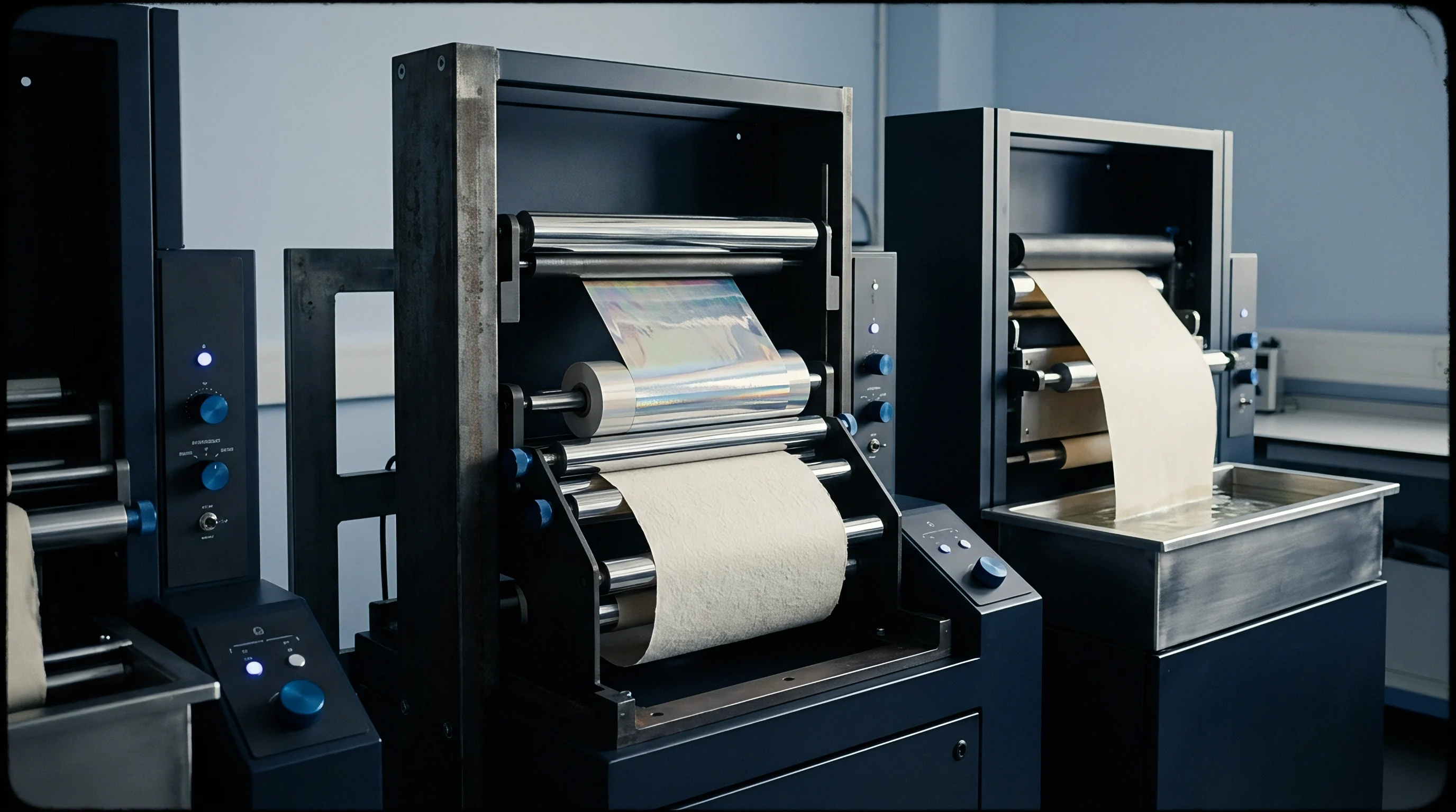
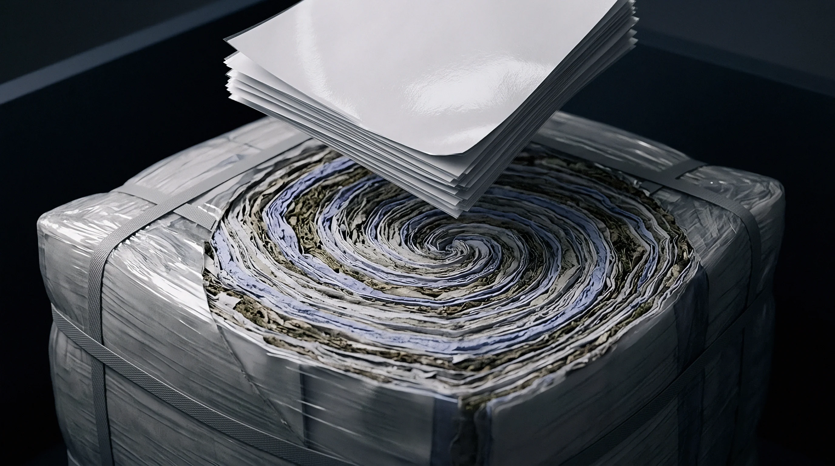
Secondary furnish roughness spikes originate from hornified fiber bundles protruding through low-density surface voids during web compression.
Mineral fillers from previous papermaking cycles recirculate through the furnish, driving secondary sheet ash content up to 18 percent. Calcium carbonate and kaolin clay aggregate when wet-end retention fluctuates on machine. Clusters exceeding 45 μm break the continuity of the top fiber ply.
Laying a 15 μm low-density polyethylene film over these nodules forces the polymer to bridge rigid peaks without thinning below functional limits or tearing outright.
White light interferometry reveals steep elevation changes across recycled sheets. Valleys with depth-to-width ratios above 0.5 prevent the polymer melt from wetting the sheet base during high-speed extrusion coating. The trapped air expands during subsequent heat-sealing, exerting internal pressure on unsupported spans of film.
Under a microscope, film ruptures trace back repeatedly to deep surface crevices where the coating spans an open cavity instead of anchoring to cellulose fibers.
Web surface pin-through defects can trace back to sudden mechanical tension surges across converting lines as much as to high shive concentrations in the incoming board furnish.
Strain
Scoring, creasing, and folding apply multi-axial strain to paperboard laminates. A steel male rule presses into a board sheet braced by a grooved female die channel, creating localized shear fields designed to produce crisp 90-degree or 180-degree folds. This shearing action shears internal fiber-to-fiber bonds within the core plies to generate controlled delamination.
That internal separation relieves surface stress, letting the board bend without rupturing outer printable liners or applied barrier layers.
Recycled furnishes disrupt this response because their internal bonding is weaker and their fibers are shorter. Z-direction tensile strength, measured under ISO 15754, falls from 450 kPa in virgin boards to below 220 kPa in recycled grades. Under the scoring rule, weak z-directional bonding produces wide, unconfined delamination across the creasing zone instead of a sharp, well-defined hinge.
Outer polymer layers absorb the resulting irregular deformation as concentrated tensile strain.
Female Die Geometry and Scoring Clearance Dynamics
Crease definition relies on tight matching between male rule width, female channel width, and channel depth relative to board caliper. Machine operators typically set channel widths through empirical rules based on sheet thickness and cross-direction tear strength. For a 400 μm virgin packaging grade, a standard 0.71 mm male rule pairs with a 1.31 mm female channel ~ calculated as board thickness times 1.5 plus the rule width.
Recycled furnishes require distinct tooling geometry to keep outer plies from cracking.
Variable sheet stiffness and lower z-directional strength in secondary stock mean standard channels place the outer plies under severe tension. Deep penetration stretches the polymer-coated face excessively. While unconstrained low-density polyethylene films exceed 300 percent elongation at break under ISO 527-3, that capacity drops below 8 percent once adhered to paperboard; fractures in the underlying fiber network focus applied strain onto narrow bands of the bonded film.
- Tool Calibration Measure delivered sheet thickness across three points per sheet using ISO 534 micrometer methods to establish baseline board caliper.
- Channel Selection Select female die grooved channel width using a 1.7 multiplier against measured caliper for recycled content exceeding 50 percent.
- Depth Adjustment Set male creasing rule penetration depth to achieve 50 percent caliper compression without severing top-layer fibers.
- Tension Balance Adjust web draw-roller torque to maintain dynamic web tension under 180 N/m during dynamic scoring passes.
- Visual Audit Inspect score lines under 20x optical magnification with cross-polarizing filters to detect early micro-fissure formation in top surface coatings.

Dynamic Converting Line Speeds and Strain Rate Sensitivities
Modern converting equipment operates at web velocities of 150 to 450 meters per minute, compressing scoring cycle durations to under 3 milliseconds. Polymer films respond directly to these deformation speeds. At moderate velocities, amorphous chains relax and reorient to absorb strain plastically.
Under high converting speeds, polymer chain mobility freezes, shifting the failure mode from ductile yielding toward brittle rupture.
Dynamic score line strain rates during high-speed converting reduce low-density polyethylene strain-to-break values from 320 percent down to 6.5 percent when bonded to fibrous substrates.
This rate sensitivity becomes especially pronounced over recycled paperboard. In virgin sheets, long softwood fibers pull through and slip against each other, distributing fold strain across a broad radius. In recycled stock, short fibers shear abruptly under low tensile loads, creating sharp stress steps at the interface.
Local strain rates in the film can surge past 1000 percent per second, blowing past its plastic yield threshold and forming micro-cracks directly over broken fiber ends.
Running high-recycled substrates with improper female channel dimensions triggers outer ply fractures, tears in moisture barriers, unscheduled line stops, and loss of carton barrier integrity.
Extrusion
Barrier retention across scored folds depends on polymer formulation, coat weight, application method, and cooling rates. Extrusion coating applies molten resin through a flat slot die onto the web, followed immediately by nip compression against a chilled chrome roll. Dispersion coating instead meters aqueous polymer emulsions via air knives or rods before drying in forced-air tunnels.
Each process yields fundamentally different morphology, internal stress fields, and mechanical adhesion on recycled stock.
Low-density polyethylene remains the standard extrusion resin for its melt processability, water vapor barrier, and sealability. Extruded at melt temperatures between 300°C and 325°C, LDPE undergoes surface oxidation, generating polar carboxyl groups that bond mechanically and chemically to fiber surfaces. Co-extruding with barrier resins like ethylene vinyl alcohol (EVOH) sharply limits oxygen transmission.
Even so, EVOH combines high stiffness with poor ultimate elongation, making it vulnerable to fracturing whenever the board is creased.
Melt Draw-Down Ratios and Residual Thermal Stresses
Extrusion dies extrude polymer through slot openings of 0.5 to 0.8 mm. Web velocity draws the melt down rapidly, thinning an 800 μm curtain down to targets of 12 to 24 μm (11.5 to 23.0 g/m² for LDPE). This aggressive draw-down ratio aligns polymer backbones along the machine direction, leaving the film mechanically anisotropic: cross-directional elongation increases, while machine-direction tear strength falls off.
Chill rolls set at 15°C to 25°C quench the molten film within 50 milliseconds. This rapid freeze restricts crystallite formation, preserving an amorphous structure that retains flexibility. At the same time, the cooling gradient between the chilled outer surface and the insulated fiber-facing layer locks residual tensile stresses into the polymer film.
When scoring forces are applied, these internal stresses combine with converting loads, lowering the external force needed to tear the coating.
- Brittle Interface Fracture Brittle rupture occurs when rigid polymer formulations crack cleanly across creased scores without significant plastic elongation, exposing raw substrate fibers.
- Adhesive Delamination Interfacial debonding happens when dynamic shearing forces overcome polymer-to-fiber adhesion, causing the film to lift away from board surface micro-crevices.
- Pin-Hole Punctuation Mechanical perforation develops when sharp, un-yielding recycled fiber ends or mineral inclusions puncture thin polymer layers under high folding pressure.
- Stress-Induced Necking Localized plastic thinning forms thin bands along score lines where polymer coat weight drops below critical functional barrier thresholds.
| Coating Material System | Coat Weight (g/m²) | Film Elongation ISO 527 (%) | Uncreased WVTR (g/m²·day) | Creased WVTR (g/m²·day) | Uncreased OTR (cm³/m²·day) | Creased OTR (cm³/m²·day) |
|---|---|---|---|---|---|---|
| LDPE Monolayer Extrusion | 15.0 | 350 | 4.2 | 8.5 | 2200 | 4500 |
| LDPE / EVOH / LDPE Co-extrusion | 18.0 (12/3/3) | 120 | 3.1 | 48.0 | 2.5 | 850.0 |
| Aqueous Styrene-Acrylic Dispersion | 12.0 | 85 | 18.5 | 145.0 | 1500 | 12000 |
| Bio-PBAT / PLA Extrusion Blend | 22.0 | 210 | 12.0 | 35.0 | 450 | 3800 |
Dispersion Coatings versus Extrusion Laminates
Aqueous dispersion barriers bypass high-temperature thermal oxidation. Synthetic latex particles ~ often styrene-butadiene or acrylic copolymers ~ coalesce as water evaporates, forming a continuous barrier. But surface tension pulls the fluid dispersion into open board voids before particles can fully coalesce.
The polymer sinks into internal pores instead of settling as a uniform top layer, creating unpredictable local thickness variations.
Folded dispersion coatings show limited crack resistance over secondary fiber substrates. Coalesced latex particles lack the long molecular chain entanglements that give extrusion-grade polymers their toughness. Tensile forces along the score line quickly surpass the cohesive limits of the dried emulsion, leaving micro-fissure networks across folds.
Laying down a heavier dispersion coat weight offers little protection; thick latex layers dry brittle, which only worsens cracking during carton forming.
Extrusion film resilience over recycled stock improves when resin melt indexes remain low and chill roll temperatures are maintained to limit polymer crystallinity.

Pinholing
Pinholing across creased board involves micro-scale fracture mechanisms that yield defects 0.5 to 50 μm across. These tiny punctures compromise the barrier, creating paths for oxygen, water vapor, oils, and liquids to penetrate the packaging wall. Pinholes do not require complete board tearing; they develop when the film ruptures over intact or partially separated fiber layers below.
Pinhole development begins when the scoring rule drives fibers into intense shear and compression. Recycled fibers, having low strain-to-break values, snap under compression along the inside fold or tear under tension on the outer shoulder. Stiffened by prior drying cycles, these broken fiber ends protrude from the damaged matrix like micro-punches pressing against the back of the polymer film.
As folding proceeds, the contact pressure exceeds the film’s puncture resistance, piercing the polymer from beneath.

What Dynamic Strain Rates Induce Film Perforation?
Line speed governs pinhole formation on creased recycled grades. At speeds below 50 meters per minute, the coating flows viscoelastically around protruding fiber tips to shed stress. Past 200 meters per minute, however, the deformation time becomes shorter than the polymer’s relaxation time.
The resin behaves as an elastic solid, failing via brittle puncture as soon as local strain over fiber tips passes the material’s dynamic limit.
High-speed footage shows pinholing clustering primarily on outer crease shoulders where elongation peaks. Secondary pinholes appear along the inside compression crease where board plies buckle outward, pinching the film against converting tools. Modeling indicates that once pinholes exceed 2 μm in diameter, gas transport shifts from Knudsen diffusion to viscous Poiseuille flow, accelerating barrier loss by several orders of magnitude.
| Web Converting Speed (m/min) | Pinhole Density (No./m of crease) | Mean Pinhole Diameter (μm) | OTR Creased ISO 15105-2 (cm³/m²·day) | WVTR Creased ISO 15106-2 (g/m²·day) | Grease Penetration Time ISO 16532-1 (min) |
|---|---|---|---|---|---|
| 30 | 0.2 | 1.1 | 12.5 | 4.8 | > 1440 |
| 100 | 1.8 | 2.4 | 45.0 | 8.2 | 420 |
| 250 | 8.5 | 5.8 | 380.0 | 22.5 | 35 |
| 400 | 24.0 | 12.2 | 1850.0 | 68.0 | 2 |

Micro-Fissure Coalescence and Gas Transport Kinetics
Under heavy converting loads, pinholes rarely remain isolated. Stresses from vibration, carton handling, and warehouse stacking cause adjacent stress fields to link up. Micro-cracks propagate from hole to hole along the score line, merging discrete punctures into open fissures.
This coalescence collapses the gas barrier, disqualifying the board for modified-atmosphere food packaging.
On 100 percent recycled paperboard coated with 18 g/m² LDPE/EVOH co-extrusion, uncreased sheets yield baseline oxygen transmission rates of 1.8 cm³/m²·day·bar at 23°C and 50 percent relative humidity under ISO 15105-2. Scoring and creasing at 150 meters per minute raises oxygen transmission to 42 cm³/m²·day·bar. Running at 350 meters per minute causes widespread pinhole coalescence, driving transmission to 1450 cm³/m²·day·bar ~ an 800-fold barrier loss stemming directly from mechanical puncture over recycled fiber fragments.
Standard purchasing contracts mandate zero grease pin-through spots along primary creased package edges over 24-hour testing periods under ISO 16532-1 protocols.
Liquid migration through pinholes follows capillary mechanics modeled by the Lucas-Washburn relation. Low-surface-tension fluids ~ including vegetable oils, fatty acids, and mineral hydrocarbons ~ penetrate these openings rapidly. Once inside the board structure, capillary suction pulls liquid throughout the fiber web, causing grease stains, softening carton corners, and creating migration pathways for recycled-furnish contaminants into packaged food.
The exact threshold where micro-scale polymer necking transitions into true open pinhole perforation across variable-density recycled stock remains difficult to predict using standard un-creased tensile test protocols.

Diagnostics
Pinholing across creased recycled board requires specific analytical procedures. Standard physical tests tailored for flat board fail to register micro-scale barrier damage introduced during dynamic folding. Effective quality control integrates dye staining, gas permeation, high-voltage electro-conductive mapping, and electron microscopy to verify barrier performance on converted packaging blanks.
Dye penetration testing per ISO 16532-1 provides a fast check of barrier integrity on scores. A colored liquid ~ usually rhodamine B or turpentine carrying red fat-soluble dye ~ rests on the crease for a defined duration. Fluid passing through pinholes wicks into the underlying fibers, showing up as red spots on the reverse side.
The method spots macroscopic leaks easily, but surface tension prevents the dye from entering defects narrower than 2 μm.
Gas Permeability and High-Resolution Dye Permeation
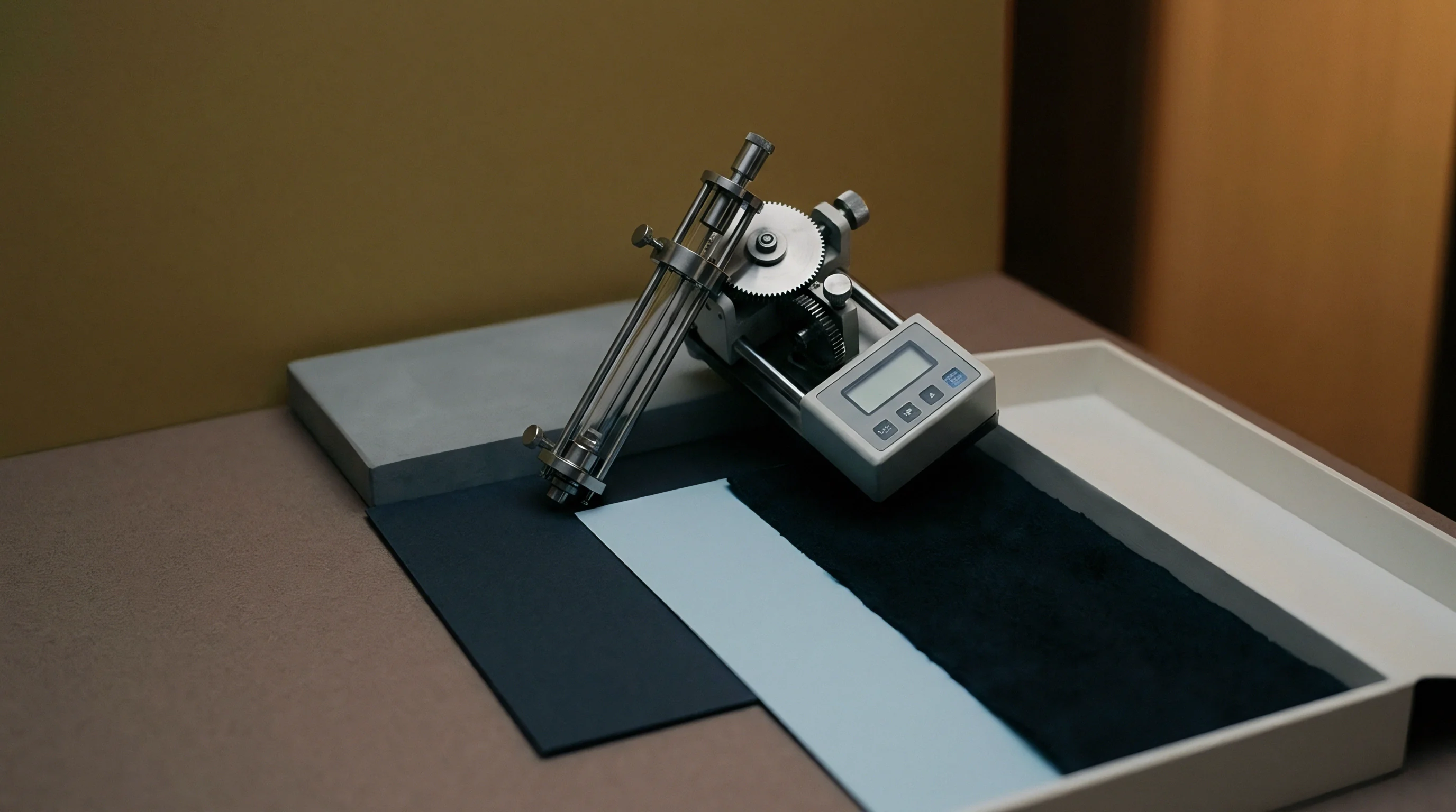
Quantifying barrier degradation requires differential-pressure gas permeation per ISO 15105-2 or coulometric detection via ASTM F1927. Specimens with centered crease lines mount directly into sealed diffusion cells. Pure oxygen blankets the coated side while a nitrogen carrier sweeps the reverse face toward the coulometric sensor.
The difference in oxygen flux between flat sheets and creased specimens isolates the barrier loss caused by score-line pinholes.
Detecting sub-micron fissures that turn away standard oils requires low-viscosity, low-surface-tension solvents. Isopropanol spiked with surfactants pulls surface tension below 22 mN/m, allowing penetration into fissures as fine as 0.3 μm. Pinhole counts per meter of score line derived this way correlate well with package shelf-life outcomes.
| Diagnostic Method | Standard Reference | Penetrant / Medium | Detection Limit (μm) | Test Duration | Defensibility Grade |
|---|---|---|---|---|---|
| Dyed Palm Kernel Oil Test | ISO 16532-1 | Dyed Vegetable Oil | 5.0 | 4 to 24 Hours | Moderate (Standard QC) |
| TAPPI Solvent Kit Test | TAPPI T 559 | Castor Oil / Toluene / Heptane | 3.0 | 15 Seconds | Low (Screening Only) |
| Coulometric OTR Permeation | ISO 15105-2 | Dry Pure Oxygen Gas | 0.1 (Gas Equivalent) | 12 to 48 Hours | High (Defensible) |
| Low-Tension Solvent Permeation | Internal Protocol | Isopropanol / Dye Mixture | 0.3 | 5 Minutes | High (Process Audit) |
| Scanning Electron Microscopy | ASTM E1588 Adapt | Electron Beam / Vacuum | 0.01 | 2 Hours | Absolute (Root Cause) |
Electro-Conductive and Microscopic Fractography Verification
Electro-conductive mapping adapts high-voltage spark testing (ASTM D5162) to thin polymer barriers on paperboard. An electrolyte-soaked sponge sweeps the coated side while a ground wire contacts the moisture-conditioned paperboard backing. When the sponge contacts a pinhole, the electrolyte completes the circuit to fire an alarm and log a count.
This technique permits continuous non-destructive inspection across the full web width on active lines.
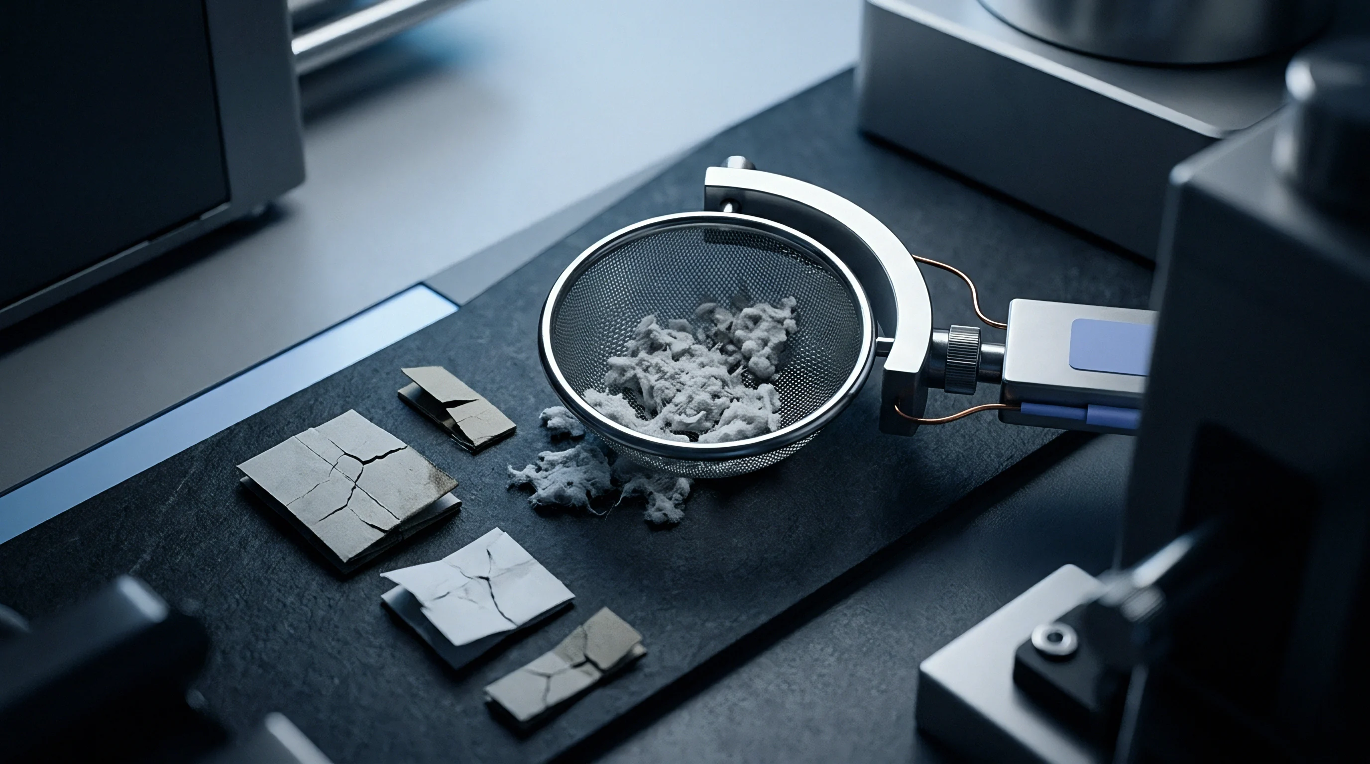
Determining root causes relies on scanning electron microscopy (SEM) and focused ion beam sectioning. Cross-sectional SEM images distinguish whether a film failed by ductile necking, direct puncture from fiber ends, mineral particle shear, or adhesive delamination. Energy-dispersive X-ray spectroscopy (EDS) at the pinhole site identifies elemental markers, distinguishing between abrasive calcium carbonate inclusions and synthetic macro-stickies.
- Sample Conditioning Condition all test specimens at 23°C ± 1°C and 50% ± 2% relative humidity for a minimum of 24 hours per ISO 187 requirements.
- Crease Standardizing Prepare laboratory creases using standardized impression tools per ISO 5638 under controlled motor-driven application speeds.
- Solvent Reagent Preparation Mix analytical grade isopropanol with 0.1% w/v Rhodamine B dye, verifying liquid surface tension remains below 22.5 mN/m.
- Permeation Cell Sealing Apply high-vacuum silicone grease along diffusion cell rim flanges to prevent edge-leakage interference during gas transport testing.
- Replicate Sampling Test a minimum of eight crease replicates per board reel to account for secondary fiber density variations across the machine width.
Standard quality assurance clauses in conversion contracts state that delivered board lots exhibiting creased dye pinhole counts exceeding 5.0 spots per meter under ISO 16532-1 test conditions permit immediate rejection of the entire material shipment.
Ledger
Substrate selection drives manufacturing economics, material yield, scrap volume, and EPR fee exposure. Balancing recycled content against barrier polymer coat weight sets the landed cost per thousand cartons. While secondary fiber pulp carries a lower per-tonne market price than virgin bleached softwood kraft, raw material savings can disappear under elevated scrap rates and the heavier coating weights needed to maintain barrier continuity.
Northern Bleached Softwood Kraft (NBSK) commands a 35 to 60 percent price premium over recycled OCC furnish. Even so, virgin kraft reaches target stiffness and flexural rigidity at lower basis weights: a 300 g/m² virgin board matches the bending resistance of a 360 g/m² recycled alternative. Because paperboard is billed by the metric tonne, that lower basis weight yields more carton blanks per ton purchased, significantly shifting unit manufacturing economics.
Downgauging Limits and Polymer Substitution Economics
To prevent pinholing over recycled stock, converters often increase extrusion coat weight or add specialized tie-layers. Raising LDPE coat weight from 15 g/m² to 25 g/m² consumes an extra 10 metric tonnes of resin per million square meters of converted board. With resin priced between $1,600 and $2,200 per metric tonne, this coating penalty adds direct material expense per thousand units, altering the financial balance between virgin and recycled substrates.
High-barrier resins like EVOH deliver gas resistance at lower thickness, but market prices exceed $5,500 per metric tonne. Because EVOH cracks easily over rough recycled creases, operations must run flexible maleic anhydride tie-layers on both sides of the barrier core. A five-layer co-extrusion stack (LDPE / Tie / EVOH / Tie / LDPE) raises tooling demands and line maintenance, shifting operational balance back toward cleaner, more uniform board furnishes.
Increasing polymer coat weight to offset substrate roughness raises extended producer responsibility fees under eco-modulated packaging waste schemes.
Waste Generation Rates and Extended Producer Responsibility Fees
Scrap generation climbs when running high-recycled substrates through scoring and folding sections. Outer ply cracking and barrier pinholes force line speed reductions from 350 meters per minute down to 200 meters per minute to keep quality within specification. Lower line speed drives up fixed machine overhead allocated per job.
Setup and run waste on recycled stock averages 4.5 to 7.0 percent, compared to 1.5 to 2.5 percent on virgin kraft.
Evolving packaging regulations add further cost pressure. Extended Producer Responsibility (EPR) regulations, including the European Union Packaging and Packaging Waste Regulation (PPWR), levy eco-modulated charges based on recyclability and composition. Packaging designs with polyolefin coatings above 15 percent of total package weight face heavy surcharges or non-recyclable classifications.
Converter economics require tracking pulp furnish costs, converting speeds, waste generation, and end-of-life fees side by side.
Calculating the true landed cost per thousand delivered packaging units requires adding pulp furnish costs, extrusion resin expenses, converting line waste losses, speed-reduction overhead penalties, and eco-modulation fee surcharges across the complete manufacturing run.