Calculating Counter Die Relief Depth across Laminated Substrate Thickness Variances
Counter die relief depth calculation requires adjusting nominal board caliper for dynamic fiber compression, film stiffness, and moisture regain clearance.
Gauge
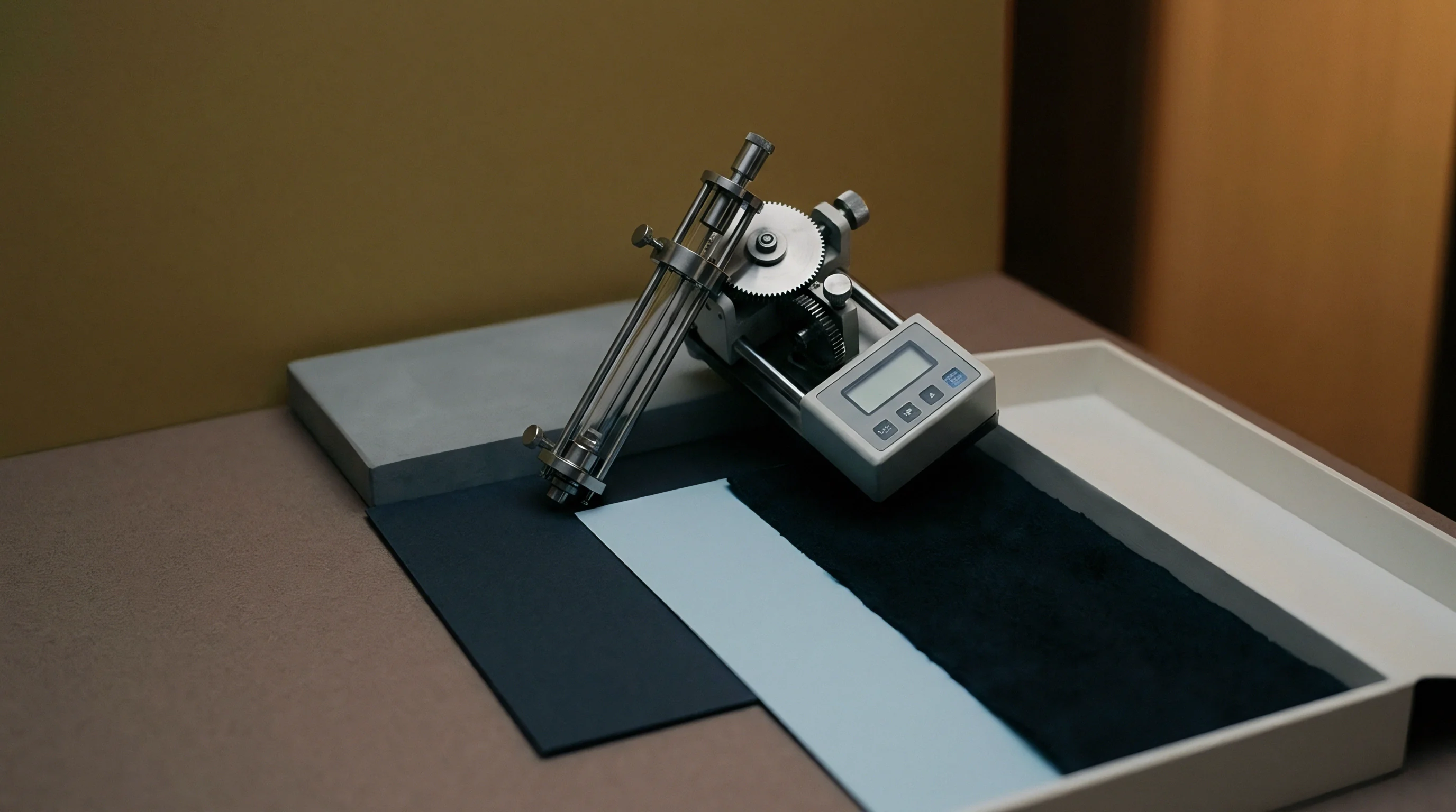
Micrometer measurements across a paperboard roll typically show clear thickness variations from edge to edge. On laminated packaging substrates, those variations compound as film layers and dry adhesive mass are added. Isolating baseline substrate caliper for tooling design requires separating three elements: raw cellulose fiber, solid adhesive film, and the polymeric outer film.
Standard static micrometer testing under TAPPI T 411 or ISO 534 applies a 50 kPa dead weight load across a 200 square millimeter presser foot. While that static reading captures uncompressed nominal thickness, it misses the dynamic compression inside a high-speed platen or rotary embossing press, where nip pressures routinely exceed 15 to 30 megapascals.
Paperboard behaves as a viscoelastic composite structure. Solid Bleached Sulfate board uses virgin bleached chemical pulp with high internal bond strength and uniform density. These chemical fibers resist crushing, yielding a predictable compression factor between 12 percent and 18 percent at standard impression tonnage.
Folding Boxboard uses a layered design where bleached chemical pulp outer liners enclose a bulky core of Mechanical Pulp or Chemithermomechanical Pulp. Containing stiff, un-delignified fibers surrounded by air voids, this mechanical core makes Folding Boxboard far more compressible ~ shrinking 25 percent to 35 percent under high-pressure embossing dies. Coated Recycled Board (or White Lined Chipboard) relies on post-consumer waste filled with short, fragmented fibers and mineral fillers, resulting in variable compressibility between 18 percent and 28 percent depending on recovered paper lots.
Film lamination tension causes curl. Adding an Oriented Polypropylene or Polyethylene Terephthalate film to the board introduces a virtually non-compressible synthetic layer. Oriented Polypropylene film, usually applied between 12 and 18 micrometers thick, offers high tensile elongation but negligible Z-axis compression under die pressure.
Polyethylene Terephthalate film at 12 to 15 micrometers exhibits higher tensile modulus and stronger puncture resistance. The solventless or water-based polyurethane adhesive underneath adds another 2 to 4 micrometers of solid polymer mass. During die entry, the film restricts localized lateral fiber movement.
When the male counter impacts a laminated sheet, this synthetic film acts like a tensioned membrane, forcing underlying cellulose fibers to absorb displacement through vertical consolidation rather than lateral shear.
ISO 534 static caliper readings overestimate effective embossing thickness by 12 percent on 350 gsm folding boxboard laminated with 12-micron PET film.
Moisture regain shifts caliper between batches. Because cellulose fibers are hygroscopic, their cross-sectional dimensions expand or contract with relative humidity. Under ISO 187 conditioning (23 degrees Celsius and 50 percent relative humidity), paperboard equilibrium moisture stays between 6.5 percent and 7.5 percent by weight.
Moving pallets from an unconditioned warehouse into a pressroom at 65 percent relative humidity pushes board moisture past 8.5 percent, swelling Z-axis caliper by 2.5 to 4.5 percent while reducing internal fiber friction. These humidified fibers compress more readily under die stroke pressure but show higher elastic recovery once released from the nip. While uncoated fiber absorbs moisture rapidly across both sides, film-laminated board takes on ambient water vapor exclusively through its uncoated reverse.
That asymmetrical moisture uptake creates hygroexpansional stress, warping panels and changing effective board height against the counter die surface.
| Substrate Classification | Nominal Caliper (µm) | Lamination Film Type | Adhesive Mass (gsm) | Static Caliper (µm) | Dynamic Compression Factor (%) | Effective Emboss Caliper (µm) |
|---|---|---|---|---|---|---|
| Solid Bleached Sulfate (SBS) | 350 | 12 µm Gloss PET | 3.0 | 365 | 14.5 | 312.1 |
| Solid Bleached Sulfate (SBS) | 450 | 15 µm Matt OPP | 3.5 | 468 | 15.2 | 396.9 |
| Folding Boxboard (FBB) | 380 | 12 µm Gloss PET | 3.0 | 395 | 28.4 | 282.8 |
| Folding Boxboard (FBB) | 500 | 18 µm Soft-Touch OPP | 4.0 | 522 | 31.0 | 360.2 |
| Coated Recycled Board (CRB) | 400 | 12 µm Gloss PET | 3.5 | 415 | 22.0 | 323.7 |
| Coated Recycled Board (CRB) | 480 | 15 µm Matt OPP | 3.5 | 498 | 23.5 | 381.0 |
Calculating accurate counter die relief requires measuring dynamic compressed caliper rather than nominal board thickness. Measuring caliper across three points on every production sheet before setting relief parameters ensures consistent relief depth. If male counter relief depth is set equal to nominal uncompressed thickness, the die over-compresses the substrate at peak stroke, causing fiber fracturing, board rupture, film delamination, and rapid matrix wear.
Conversely, calculating relief depth purely from compressed thickness without clearance for elastic spring-back leaves the finished emboss lacking sharp perimeter definition and height. Reliable relief calculation requires establishing composite thickness under maximum tonnage, adding the elastic recovery coefficient for that fiber blend, and subtracting clearance factors derived from shoulder geometry.
Whether non-destructive ultrasonic caliper profiling can predict localized fiber density variations prior to tool fabrication remains open to field validation across re-pulped board lots.
Matrix
Male counter plates push paperboard fibers into female die cavities, where precise matching between punch and cavity determines the sharpness, relief height, and surface quality of the impression. Tooling materials vary based on run length, substrate density, and press type. Primary options include resin-impregnated fiber counterboards, vulcanized paper matrix, photopolymer counter plates, liquid epoxy poured against the female die, and CNC-milled solid brass counters.
Vulcanized paper allows fast make-ready carving but deforms over repeated cycles. Photopolymer counters deliver clean image reproduction but soften when press operating temperatures exceed 55 degrees Celsius. CNC-milled brass counters hold dimensional stability across multi-million impression runs, resisting thermal degradation and mechanical creep.
Male and Female Die Clearance Geometry
Clearance is the mechanical gap between the side wall of the male punch and the vertical edge of the female cavity. This gap must match the dynamic compressed thickness of the laminated substrate plus a localized relief tolerance factor. Setting clearance equal to uncompressed nominal board caliper lets the sheet sit loosely in the cavity, yielding rounded perimeters and soft definition.
Dropping clearance below dynamic compressed thickness causes the counter to pinch the substrate against the cavity wall, shearing cellulose fibers along the shoulder, splitting film laminates, and causing pinhole cracks. Calculations must also factor in the shoulder draft angle of the female tool. Standard angles are 30, 45, or 60 degrees.
Steeper 30-degree shoulders produce sharp geometric edges but concentrate heavy shear stress at the film-board interface; shallower 60-degree angles spread strain across a wider transition, protecting fragile films at the expense of crisp relief.
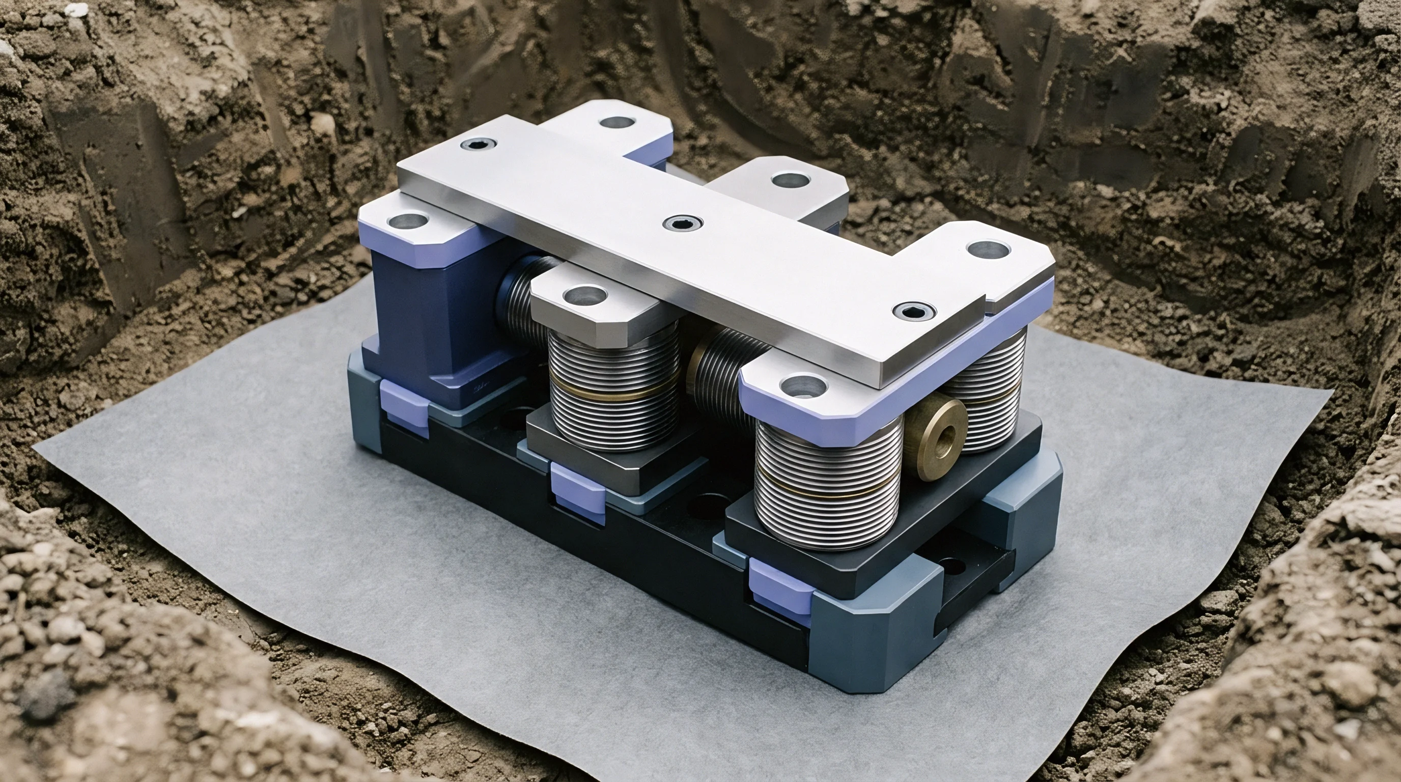
Counter Board Rheology and Material Selection
Counter materials deform under pressure to match female tooling geometry. During make-ready bring-up, the male counter undergoes plastic deformation under tonnage to shape relief peaks and channels. Fiberglass-reinforced epoxy resin plates show minimal cold flow under continuous impact.
Elastomeric counter plates compress elastically, storing energy that drives laminated board into narrow female recesses. However, elastomeric materials suffer high lateral displacement under vertical pressure. This lateral creep widens punch profiles over long runs, closing up side clearance and shearing board edges.
Evaluating substrate compression characteristics under active load prior to selecting counter matrix compositions prevents lateral deformation and premature tooling wear.
ISO 12647-2 tolerance standards for post-press finishing specify a maximum dimensional deviation of plus or minus five micrometers across counter plate relief profiles.
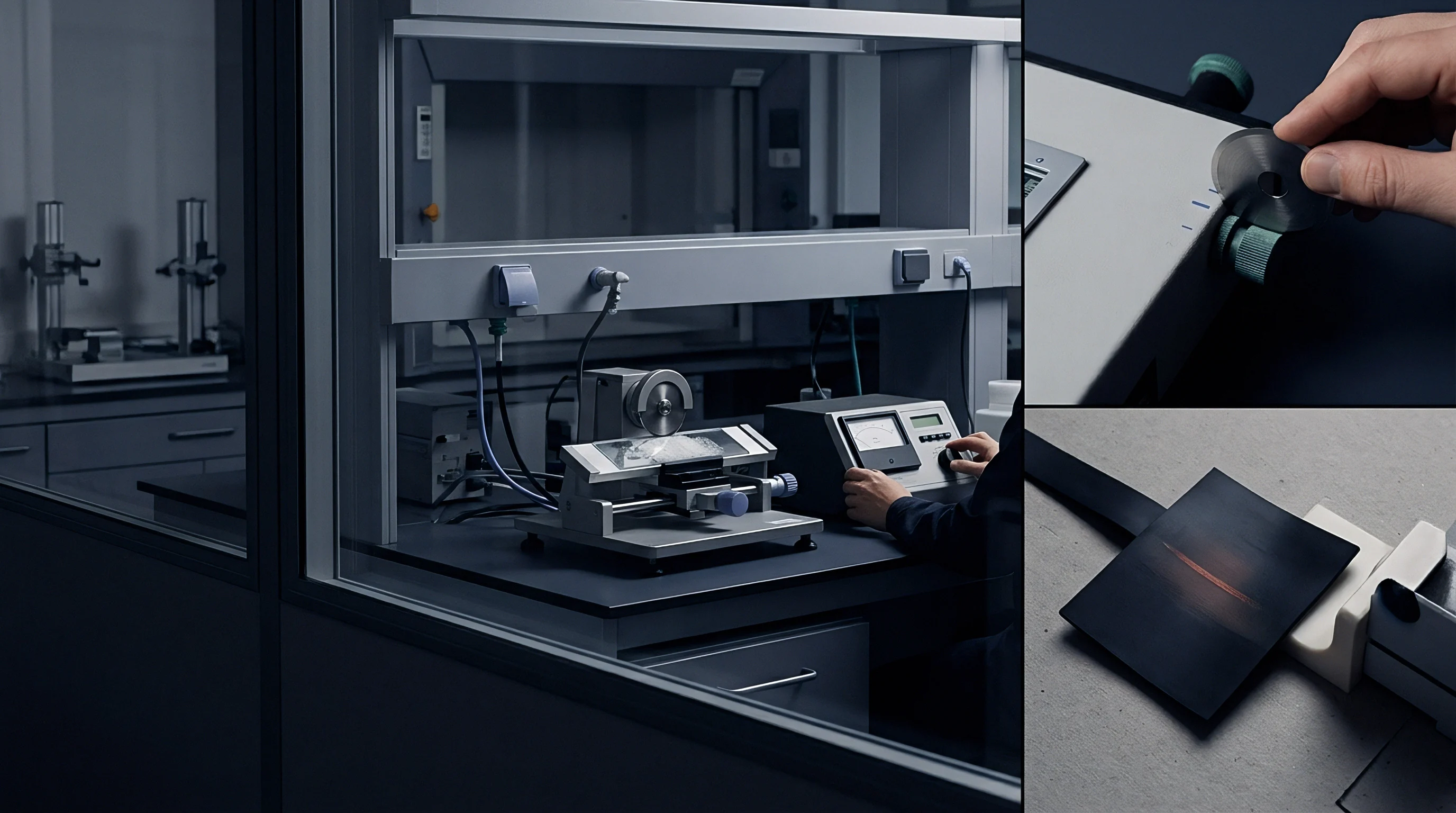
Embossing Failure Modes from Inaccurate Counter Depth
Miscalculating relief depth leads directly to defects on the converting floor. Excessive male counter height forces the top surface of the substrate against the female cavity ceiling hard enough to exceed paperboard burst strength. Insufficient relief height leaves air gaps, creating flat, undefined image crowns.
- Film Shear Rupture occurs when male punch clearance falls below dynamic compressed caliper, tearing outer polypropylene or polyester films along perimeters during die entry.
- Lamination Delamination develops when local shear forces overcome adhesive bond strength, causing synthetic film to pull away from base board along relief shoulders.
- Internal Board Flaking manifests within Folding Boxboard middle layers when excessive tonnage crushes mechanical pulp structures into powder, destroying panel rigidity.
- Crown Flattening results from under-calculating male relief height, preventing substrate contact with the deepest sections of the female cavity at peak dwell.
- Matrix Ghosting appears on the reverse of the sheet when overly hard male counter materials leave heavy indentations that telegraph through single-wall folding cartons.
Selecting a steeper shoulder angle on male counter dies demands softer counterboard materials to absorb thickness spikes without tearing the laminated film overlay.
Relief
Calculating counter depth depends on establishing composite material thickness under maximum press tonnage. The mathematical model accounts for five variables: baseline substrate caliper, adhesive layer thickness, lamination film thickness, substrate compressibility factor, and elastic recovery ratio. Nominal overall thickness is only a starting point; dynamic thickness at peak impression force dictates target male punch height and matrix channel depth.
The mathematical relationship governing target male counter relief depth follows sequential steps:
Mathematical Formulation of Male Counter Height
Total nominal uncompressed caliper (t_n) equals the sum of raw board caliper (t_b), adhesive dry layer thickness (t_a), and film lamination thickness (t_f):
t_n = t_b + t_a + t_f
Dynamic compressed substrate thickness (t_c) incorporates the substrate compressibility factor (C_f) and film compression factor (C_film):
t_c = t_b (1 – C_f) + t_a + t_f (1 – C_film)
Because polyester and polypropylene films compress less than 3 percent under standard converting tonnages, C_film is routinely set to 0.02. Substrate compressibility factor C_f varies by pulp type: 0.15 for SBS, 0.30 for FBB, and 0.22 for CRB.
Target male counter relief height (R_m) determines how far the punch extends from the counter base plate, calculated from female cavity depth (H_f), dynamic compressed substrate thickness (t_c), and fiber elastic recovery ratio (E_r):
R_m = H_f – t_c + (t_c E_r)
Fiber elastic recovery ratio E_r represents proportional post-impression fiber rebound ~ typically 0.08 for virgin chemical fibers and 0.04 for recycled stock. Male counter side clearance (S_c) specifies total clearance per side between male punch wall and female cavity wall:
S_c = t_c (1 + K_s)
Where K_s is the film strain factor: 0.00 for unlaminated board, 0.08 for 12-micron PET film, and 0.12 for 15-micron OPP film to compensate for lateral stretch during impression entry.
Accounting for Moisture Regain and Film Tension
Moisture changes alter dynamic compressed thickness during long runs. Higher ambient humidity increases fiber moisture, softening hydrogen bonds within the paperboard matrix and raising initial compressibility under load (bumping C_f by up to 0.05). Under rapid high-speed nip compression, however, wet fibers exert greater hydrostatic resistance, creating temporary Z-axis pushback that shifts effective relief clearance.
Film tension adds a competing force: oriented film stretched across the sheet resists forming into deep cavity recesses. If male counter relief height does not provide sufficient displacement force, film tension pulls the board out of cavity corners, rounding off relief profiles.

Stepwise Relief Depth Calculation Method
- Measure Baseline Uncompressed Caliper across ten randomized sheet locations with a calibrated micrometer, recording minimum, maximum, and mean values.
- Determine Fiber Compressibility Factor from mill certification sheets or dynamic lab nip compression testing at target tonnage.
- Calculate Dynamic Compressed Caliper using film, adhesive, and compressed substrate variables in the secondary thickness formula.
- Establish Female Cavity Depth and Draft Angles from CAD tooling profiles provided by the engraver or die maker.
- Compute Target Male Relief Height using fiber elastic recovery coefficients to avoid over-compression and board tearing.
- Verify Side Clearance Parameters against film strain factors so lamination layers clear cavity shoulders without micro-fracturing.
- Mill or Cut Male Counter Matrix to calculated dimensions using CNC equipment or laser-ablated photopolymer plate processors.
Deep relief counter tooling designed for brittle film laminates requires generous shoulder radii to prevent localized strain concentrations during the impression stroke.
| Substrate Base & Film Spec | Raw Board Caliper (µm) | Nominal Caliper t_n (µm) | Compressibility C_f | Compressed Caliper t_c (µm) | Female Cavity Depth H_f (µm) | Calculated Male Height R_m (µm) | Calculated Clearance S_c (µm) |
|---|---|---|---|---|---|---|---|
| SBS + 12 µm PET Film | 350 | 365.0 | 0.15 | 312.2 | 500.0 | 212.8 | 337.2 |
| SBS + 15 µm OPP Film | 450 | 468.5 | 0.15 | 400.7 | 600.0 | 231.4 | 448.8 |
| FBB + 12 µm PET Film | 380 | 395.0 | 0.30 | 280.7 | 500.0 | 241.8 | 303.2 |
| FBB + 18 µm Soft OPP | 500 | 522.0 | 0.30 | 371.7 | 750.0 | 393.0 | 416.3 |
| CRB + 12 µm PET Film | 400 | 415.5 | 0.22 | 327.2 | 500.0 | 185.9 | 353.4 |
| CRB + 15 µm OPP Film | 480 | 498.5 | 0.22 | 392.6 | 650.0 | 273.1 | 439.7 |
Fabricating male counter dies without accounting for film stiffness causes widespread delamination, forcing tooling remachining and delaying line bring-up.
Deformation
High-speed rotary and platen presses generate dynamic forces that alter substrate thickness during impression. Heavy tonnage causes mechanical press deflection, bowing the bed and platen outward by several hundredths of a millimeter at the center. This reduces impression force in the middle of the sheet while concentrating tonnage along the outer chase borders.
Counter matrix materials also deform under continuous impact: resin-impregnated fiber boards lose thickness permanently over thousands of impressions, reducing male counter relief height, while elastomeric and photopolymer counters suffer thermal creep from internal frictional heat. Running platen presses past 6,000 sheets per hour heats up the counter, softening polymer structures and altering side clearance geometry.
Hot Stamping Thermal Drift and Tooling Expansion
Integrated hot foil stamping and embossing introduces thermal expansion variables. Female brass or copper dies mount onto heated honeycomb chases held between 110 degrees Celsius and 140 degrees Celsius. Copper has a thermal expansion coefficient of roughly 16.5 x 10^-6 per Kelvin; brass expands at 18.7 x 10^-6 per Kelvin.
Heating a 600 millimeter copper chase from an ambient 20 degrees Celsius to an operating 120 degrees Celsius expands the plate length by roughly 0.99 millimeters, shifting female cavities outward from the centerline. Because male counter plates mount on unheated lower platens near room temperature, this thermal differential misaligns male punches against female cavities. Thermal drift tightens side clearance along outer cavity perimeters while widening it on inner edges, causing punches to crush substrate edges, shear film laminates, and spoil impression definition.
How Much Counter Clearance Prevents Substrate Shearing?
Preventing substrate shearing requires adjusting male counter side clearance for dynamic thermal drift and moisture swelling. Minimum clearance should equal dynamic compressed board thickness plus the total thermal expansion offset of the heated female die divided by the number of cavity impressions across sheet width. On a multi-up layout with ten cavity rows across a 1,020 millimeter sheet, thermal growth shifts outer cavities by more than 0.40 millimeters relative to the unheated counter.
Operators must apply localized make-ready patching or use heat-resistant epoxy counters on aluminum sub-bases with matching thermal expansion to prevent misalignment shear.
Thermal growth across multi-up copper embossing plates reduces effective female cavity depth while narrowing clearance channels.

Dynamic Caliper Flattening under High Line Speeds
At high line speeds, impression dwell drops below 50 milliseconds per sheet. Rapid loading increases apparent fiber stiffness because air cannot evacuate internal voids quickly enough. Trapped air inside Folding Boxboard mechanical pulp layers creates a pneumatic cushion on impact.
When the press opens, this compressed air expands rapidly against the newly formed crown. If the lamination film was stretched past its yield point during that brief impression stroke, expanding air forms micro-bubbles underneath, blistering the film. Adjusting clearances compensates for batch moisture shifts and protects liner integrity during run cycles.
Pressroom operational routines should address mechanical drift, thermal growth, and dynamic compression through regular checks during long runs:
- Check Thermal Equilibrium by monitoring chase heating zones with infrared thermography to confirm uniform heat distribution before locking counter positions.
- Verify Impression Tonnage using load cell sensors across all four platen corners to spot and correct platen deflection or frame bowing.
- Inspect Counter Matrix Integrity every 10,000 sheets to catch thickness loss, edge breakdown, or material creep in photopolymer counters.
- Monitor Sheet Moisture Content at the feeder pile using non-contact moisture meters to adjust relief clearance for environmental swelling.
- Recalibrate Male Punch Alignment after any press stop over fifteen minutes to compensate for cooling in heated chases.
Mill-side substrate caliper fluctuations beyond standard delivery tolerances are a primary cause of lost embossing detail on long runs.
Allowance
Procurement documents for die-cutting and embossing tooling set exact dimensional margins for male and female counters. Yet die quotes often list tooling costs as isolated line items without detailing the engineering needed to match counter relief depth to specific substrate batches. Buyers need complete technical dockets from die makers ~ including explicit dynamic compression assumptions, cavity depths, draft angles, and side clearance calculations.
When board caliper varies by more than plus or minus 5 percent across mill deliveries, fixed-depth counter plates fall short. Ordering counters built strictly to nominal caliper forces operators into extensive manual make-ready patching on press, adding non-productive setup time and driving up scrap.
Scrap allowance calculations have to cover make-ready waste and running defects caused by incorrect counter depth. Bringing up a complex combination hot foil stamping and embossing job on a 1,020 millimeter platen press consumes 500 to 1,500 make-ready sheets before achieving acceptable register and depth. If male counter relief depth is off, make-ready waste spikes when operators crank up press tonnage to compensate.
Over-pressuring crushes un-embossed packaging panels, permanently thinning caliper across the folding carton blank and rendering cartons useless on automatic filling lines. Specifying shoulder relief angles on every tooling RFQ ensures process repeatability when board moisture and tooling tolerances vary.
Deep relief embossing affects the recyclability and repulpability of film-laminated board. Under standard European recycling protocols, such as CEPI guidelines or PTS test method PTS-RH 021/97, laminated packaging board is mechanically pulped to separate cellulose fibers from synthetic films. High-relief embossing stretches film layers past their yield point.
If stretched film shatters during mechanical pulping, it forms rigid fragments (micro-plastics or sticky contaminants) small enough to pass through coarse screening mesh (0.15 millimeter slot size), contaminating recycled pulp streams and degrading fiber value. Keeping lamination films intact through accurate counter clearance lets film separate in large sheets during hydrapulping, helping the substrate pass municipal waste audits with high recyclability scores.
| Counter Die Material | Tooling Cost Index (Base = 1.0) | Dimensional Drift Tolerance (µm) | Maximum Rated Impressions | Make-Ready Time (Hours) | Recylability Impact of Board Stress |
|---|---|---|---|---|---|
| Vulcanized Paper Counterboard | 1.0 | ± 25 | 25,000 | 2.5 | Low – soft counter prevents film fracturing |
| Photopolymer Plate Counter | 1.8 | ± 15 | 100,000 | 1.2 | Moderate – softening alters side clearance |
| Glass-Epoxy Resin Counter | 2.5 | ± 8 | 250,000 | 1.5 | Low – high stability protects film integrity |
| CNC-Milled Brass Male Die | 4.2 | ± 3 | 1,000,000+ | 0.8 | Controlled – absolute dimensional control |
Unit pricing models must factor in extra finishing passes and tool maintenance. Ordering a single-pass combination hot-stamping and embossing die incurs higher upfront costs, but it eliminates second-pass registration errors and cuts press running hours in half. Even so, combination tooling demands exact counter relief calculations because foil transfer temperature and impression force act in the very same nip stroke.
Miscalculating male relief height ruins both foil adhesion and embossing definition, rendering expensive brass tooling useless. Setting strict quality agreements with substrate mills and engravers protects converters from absorbing the cost of re-milled tooling and spoiled stock.
Standard procurement contracts incorporating DIN 55405 specifications give converters the right to bill buyers for counter die re-milling whenever delivered substrate caliper strays more than six percent from baseline job dockets.