Calculating Substrate Compression Ratios in Embossing Operations
Substrate compression ratio measures z-axis compaction, balancing tool impression depth against fiber strain limits to maximize embossing height without shearing.


Caliper
Structural board thickness establishes the primary volumetric baseline before die engagement. Fiber matrices contain significant internal air space that collapses under compressive mechanical force. Predicting how much a substrate compresses during embossing requires isolating its initial uncompressed bulk and void fraction from its ultimate solid fiber volume.
Initial Sheet Geometry and Void Fraction
Fiber distribution in virgin bleached sulfate matrix sets an uncompressed density near seven hundred kilograms per cubic meter. Voids between cellulose fibers account for roughly thirty to fifty percent of total paperboard volume prior to mechanical deformation. Solid bleached sulfate, folding boxboard, and coated recycled board react differently under identical hydraulic press tonnages due to variations in fiber length and ply stratification.
Solid bleached sulfate resists shear stress effectively, yielding uniform volumetric compaction across high-pressure nip zones. Folding boxboard features groundwood or thermo-mechanical pulp in its middle plies, creating higher bulk with greater initial void volume. Coated recycled board displays lower elastic recovery because reprocessed fibers possess shorter average lengths and higher mineral filler content.
Tool alignment dictates density.
| Substrate Grade | Grammage (gsm) | Nominal Caliper (μm) | Initial Apparent Density (g/cm³) | Estimated Void Fraction (%) |
|---|---|---|---|---|
| Solid Bleached Sulfate (SBS) | 350 | 450 | 0.778 | 48.1 |
| Folding Boxboard (FBB) | 300 | 480 | 0.625 | 58.3 |
| Coated Recycled Board (CRB) | 400 | 520 | 0.769 | 48.7 |
| Values measured under standard conditioning per ISO 187 at 23 degrees Celsius and 50 percent relative humidity. Static caliper measured using ISO 534 dead-weight micrometer method. | ||||
Measurement Protocols for Uncompressed Board
Standardized micrometer testing applies static physical loads across specified contact presser feet to isolate raw substrate thickness. Standard micrometers utilize a pressure of fifty kilopascals applied over a two-square-centimeter presser foot per ISO 534. Static measurements capture bulk thickness but fail to reflect dynamic fiber behavior under instantaneous nip pressures exceeding ten megapascals.
Dynamic compression testing utilizes high-speed material testing systems to simulate press nip conditions. Rapid pressure spikes force air out of inter-fiber channels, compressing the matrix toward absolute fiber density. Pure cellulose exhibits a solid density of approximately one point five grams per cubic centimeter.
Substrate compression calculations use this theoretical limit as the absolute zero-void boundary.
Inaccurate initial thickness measurements lead to excessive tool penetrations that rupture surface coatings across full production runs.

Nip
Platen and cylinder embossing equipment compress paperboard through concentrated line loads applied across microscopic timeframes. Compressive stress within the nip depends on machine velocity, tool curvature, and counter-die hardness. Tooling geometry determines the local deformation profile while mechanical platen settings dictate overall tonnage.
Impression Force and Dynamic Dwell Dynamics
Rotary cylinder systems concentrate deformation forces along a narrow area of contact. The linear contact strip creates a sharp pressure profile where maximum compressive stress occurs at the nip midpoint. Line loads in rotary sheet-fed conversion typically range from forty to one hundred twenty Newtons per linear millimeter.
At a press speed of two hundred meters per minute, a rotary embossing nip provides a dwell time under three milliseconds.
Nip dwell governs compaction. Flatbed platen presses provide extended contact durations ranging from eighty to two hundred milliseconds. Longer dwell times allow viscoelastic fiber movement, enabling higher permanent compression ratios at lower peak impression forces.
Friction generates localized heat. Heat softens internal lignin, lowering resistance to permanent structural collapse.
Tool Clearance Parameters and Male Female Alignment
Machined clearances between engraved steel tools and counter dies determine the minimum physical gap under peak platen load. Male tool elements push paperboard into female counter cavities, creating combined tensile, shear, and compressive forces. The clearance gap between male relief walls and female recessed walls regulates lateral fiber squeezing.
Counter-die shore hardness alters depth. Resilient counter materials like polyurethane or compressed fiberboard flex under load, broadening the nip zone and reducing localized strain. Rigid counter dies made of photo-cured resin or steel transfer full hydraulic tonnage directly into the substrate.
Direct force transfer achieves sharp definition but increases failure risks at high compression levels.
- Audit incoming sheet caliper consistency across three points of the web to establish correct initial gauge settings.
- Verify counter die shore hardness rating using a durometer before mounting tools into the chasing frame.
- Set initial mechanical stops to maintain a minimum clearance equal to sixty percent of nominal board thickness.
- Execute a pressure drawdown test with carbon transfer film to evaluate impression distribution across the die plate.
- Measure post-emboss relief depth with an optical micrometer to confirm target compression levels without coating micro-fractures.
Die engravers frequently attribute unexpected surface cracking to substrate batch variation rather than excessive male tool relief.

Density
Calculating Z-direction material compaction requires comparing uncompressed bulk against compressed thickness at peak platen displacement. Real compression ratio calculation evaluates instantaneous strain during tool engagement alongside permanent residual strain remaining after viscoelastic relaxation. Substrate density increases continuously as tool penetration compresses available void spaces.

Mathematical Model of Z-Direction Volume Reduction
Substrate strain calculations utilize nominal starting thickness and depth of tool engagement to establish instantaneous volumetric change. The instantaneous strain formula defines total compaction relative to initial caliper:
Instantaneous Strain = (Initial Caliper – Compressed Thickness) / Initial Caliper
Pressure drives void collapse. Consider a job utilizing 350 gsm Solid Bleached Sulfate board with an initial caliper of 450 micrometers. The starting apparent density calculates to 0.778 grams per cubic centimeter.
The embossing die configuration forces the substrate into a compressed gap of 200 micrometers at peak platen stroke.
The calculation yields an instantaneous strain of (450 – 200) / 450 = 0.5555, representing a 55.6 percent reduction in caliper. Under peak mechanical load, the localized apparent substrate density reaches 1.750 grams per cubic centimeter. Localized density figures exceeding the cellulose wall density of 1.500 grams per cubic centimeter indicate lateral fiber extrusion outside the male die contact area.
| Process Stage | Thickness (μm) | Apparent Density (g/cm³) | Compression Ratio (%) | Substrate State |
|---|---|---|---|---|
| Uncompressed Baseline | 450 | 0.778 | 0.0 | Initial Uncut Board |
| Peak Impression Nip | 200 | 1.750 | 55.6 | Maximum Dynamic Strain |
| Immediate Elastic Recovery | 260 | 1.346 | 42.2 | Press Exit Relief |
| Conditioned Equilibrium (72 h) | 280 | 1.250 | 37.8 | Final Permanent Relief Height |
ISO 534 specifies static micrometric pressure at fifty kilopascals for caliper determination before converting.

Sensitivity Analysis across Impression Depths
Linear increases in die penetration generate exponential resistance forces as fiber structures reach maximum physical packing. Fibers deform permanently. Initial strain up to thirty percent relies on void space reduction without crushing individual cellulose fiber walls.
Exceeding forty-five percent strain causes structural damage within the fiber network. Tensile stress across the relief bevel edges increases drastically as compressed material resists further density gains. Solid bleached sulfate resists shear.
Compression ratios exceeding fifty percent require extreme hydraulic pressure, accelerating die wear and risking ply separation.
Standard purchasing specifications for converting tools invoke ISO 12647 quality limits to restrict maximum allowable clearance deviations to five micrometers.


Relief
Engraved female pockets and matching male projections define the three-dimensional geometry imposed on paperboard structures. Female pocket depth dictates maximum potential relief height while wall angles determine stress distribution along detail edges. Tool designers balance visual pop against substrate mechanical rupture limits.
Can Compression Ratios Exceed Fibrous Mechanical Limits?
Exceeding fifty-five percent strain ruptures hydrogen bonds holding cellulose fibers together within the internal matrix. Fibers slip past each other, destroying internal ply cohesion. Fiber bonds break under strain.
Excess pressure splits board.
Recycled fibers lack strength. Secondary fibers in coated recycled board contain damaged cell walls that fail rapidly under localized compressive stress. Pushing recycled grades beyond a forty percent compression ratio causes surface cracking along emboss bevels.
A bevel angle below forty-five degrees transfers crushing energy into lateral shear that splits outer surface coatings.
Bevel Geometry and Shear Stress Concentration
Tapered sidewall angles mitigate lateral force concentrations where die edges press into paperboard plies. Draft angles between forty-five and sixty degrees distribute tensile strain smoothly across the embossing shoulder. Steeper bevel angles under thirty degrees concentrate cutting forces along the top crest, shearing surface coatings.
- Coating shear along embossing edges destroys surface barrier integrity and exposes unbleached internal fibers to ambient moisture.
- Internal ply delamination creates invisible air pockets that compromise carton compression strength during pallet stacking.
- Pinholing at sharp corners ruins grease and moisture barrier performance in food packaging board configurations.
- Surface mottling within deep recesses indicates uneven fiber compaction across variable grammage zones within recycled furnish stock.
Softer counter dies cushion impact forces but lose dimensional definition across long production runs.

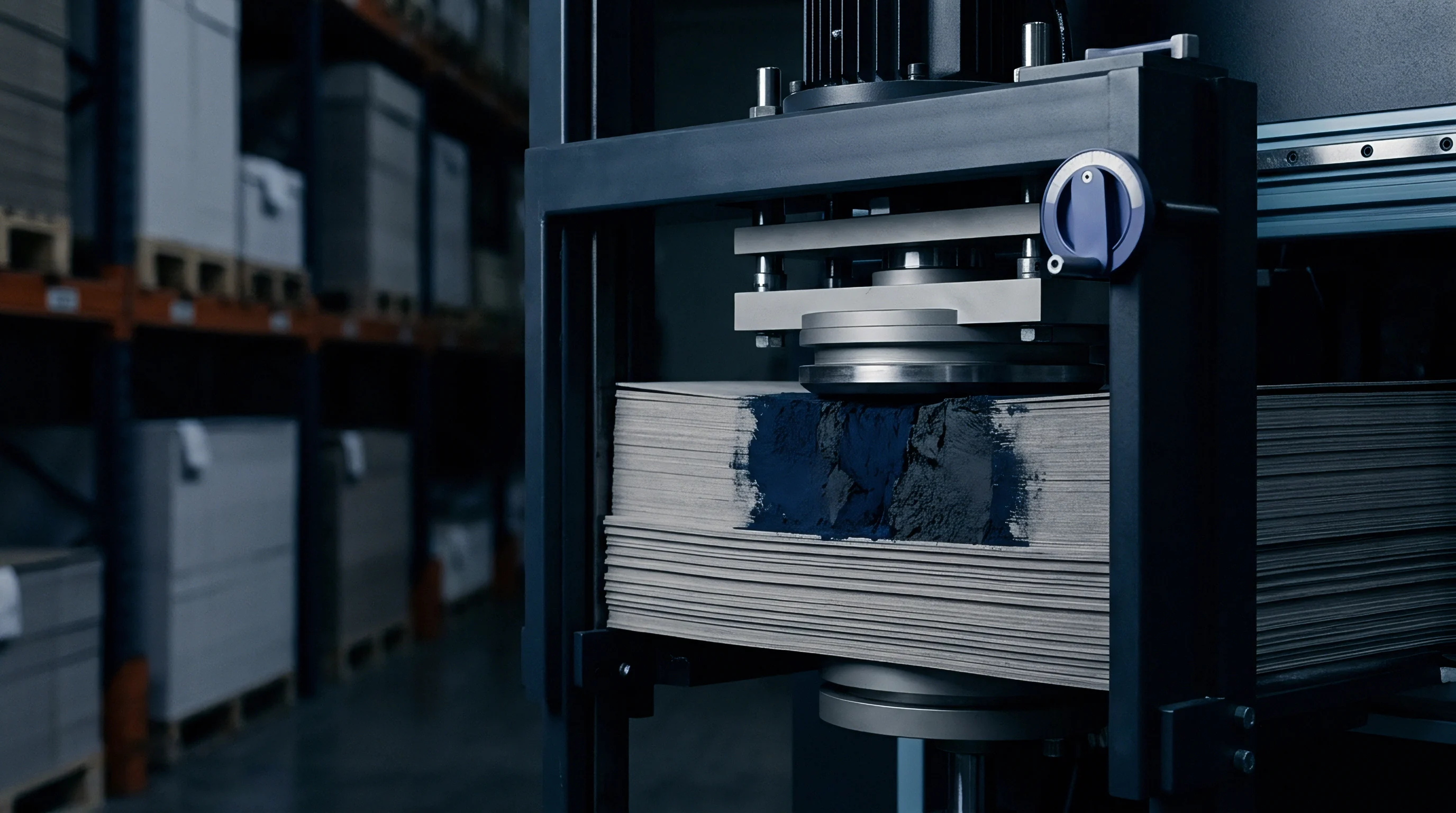
Rebound
Post-impression elastic springback alters the final dimensional profile of embossed paperboard over time. Viscoelastic materials display immediate elastic recovery upon exiting the press nip, followed by slow delayed strain recovery. Ambient temperature and relative humidity influence the rate and magnitude of post-press relaxation.
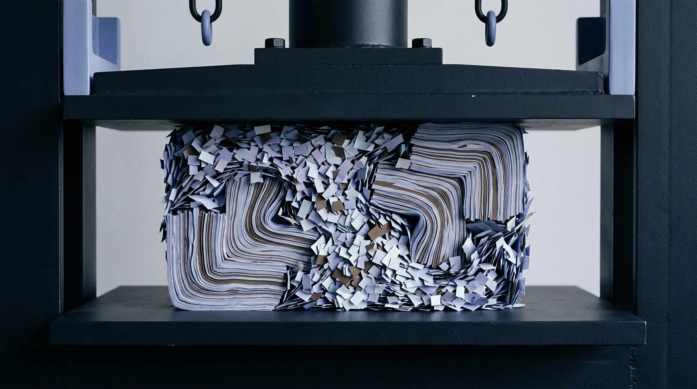
Viscoelastic Recovery and Moisture Dynamics
Internal moisture content acts as a plasticizer within cellulose polymers, controlling structural relaxation after press release. Water molecules break and re-form secondary hydrogen bonds, allowing compressed fiber networks to spring back toward original uncompressed caliper. Moisture alters springback behavior.
Paperboard converted at six percent moisture content retains embossed relief height far better than board converted at eight point five percent moisture content.
Moisture regain in high-humidity storage relaxes internal fiber stresses and reduces embossed relief height.
Elevated moisture plasticizes the fiber web, accelerating dimensional decay over seventy-two hours post-conversion. Heated embossing dies mitigate springback by thermally setting cellulose fibers under pressure. Die temperatures between eighty and one hundred twenty degrees Celsius permanently soften amorphous hemicellulose, locking compressed zones into place before elastic forces recover.

Long Term Dimensional Stability and Stacking Loads
Compressive forces exerted by stacked pallets accelerate structural relaxation in deep relief patterns. Elastic recovery reduces depth. Boxboard stored in climate-controlled environments maintains ninety percent of initial embossed relief depth after thirty days.
Uncontrolled warehouse storage at high relative humidity causes structural relaxation, losing up to thirty percent of decorative relief height.
| Time Post-Impression | SBS Relief Depth (μm) | FBB Relief Depth (μm) | CRB Relief Depth (μm) | Average Springback (%) |
|---|---|---|---|---|
| 0 Hours (Nip Exit) | 250 | 280 | 240 | 0.0 |
| 1 Hour | 220 | 240 | 215 | 12.7 |
| 24 Hours | 195 | 210 | 190 | 22.2 |
| 72 Hours (Equilibrium) | 190 | 200 | 185 | 25.3 |
- Extract ten sample cartons immediately after platen exit to measure initial relief depth with an optical profilometer.
- Place five samples in a climate cabinet maintained at twenty-three degrees Celsius and fifty percent relative humidity.
- Store five remaining samples under a five-kilogram static weight to simulate warehouse stacking conditions.
- Re-measure relief depth at twenty-four, forty-eight, and seventy-two hour intervals to calculate total dimensional springback.
- Record permanent compression percentage to establish true finished tool performance under long-term storage conditions.
The exact molecular mechanisms governing long-term hydrogen bond reformation in highly compressed secondary fibers remain subject to ongoing laboratory investigation.