Piezoelectric Stress Wave Analysis in Rotary Die Scoring Operations
Piezoelectric stress wave monitoring detects cartonboard score cracking in real time by capturing high-frequency elastic strain transients at rotary die nips.


Transduction
Arrays of piezoceramic sensors mounted on rotary tool shafts convert mechanical strain transients into continuous electrical potential differentials. As male scoring rules strike paperboard web stock, localized compression generates elastic wave packets that propagate through the cylinder mass. These stress waves travel at sonic velocity through hardened alloy steel toward transducers mounted on bearer rings and bearing housings, providing direct insight into fiber displacement, ply delamination, and structural yield during high-speed converting operations.
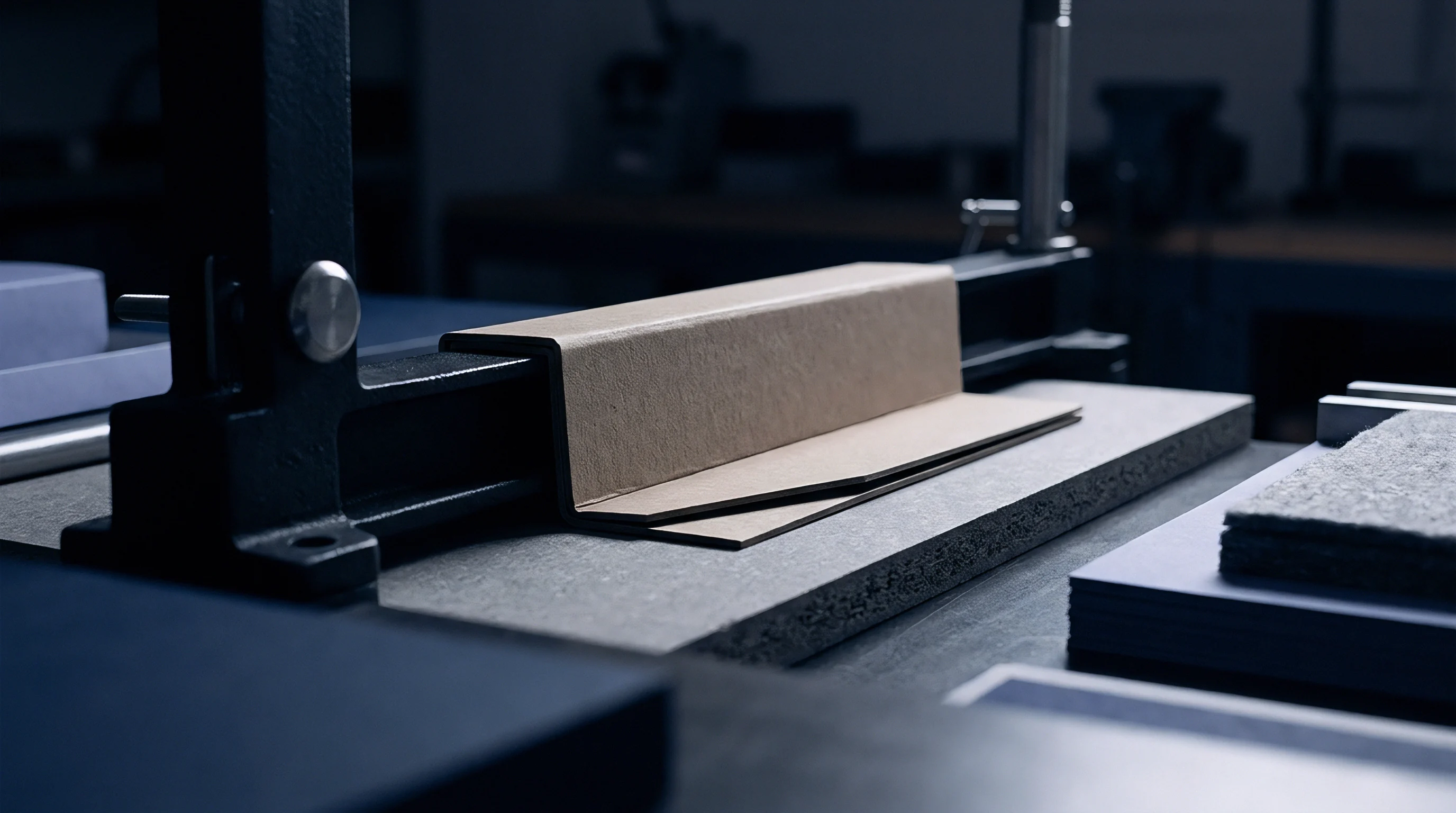
Score formation depends on controlled mechanical failure inside internal paperboard layers. The scoring rule must compress inner plies while leaving the top and bottom linerboard surfaces undamaged. As the rule penetrates folding boxboard or solid bleached sulfate, fibers yield under shear and compressive stresses, releasing elastic strain energy as transient stress waves between 50 kilohertz and 500 kilohertz.
Capturing these signals requires direct physical contact between the transducer and the rotating die, using slip ring assemblies or wireless telemetry transmitters to feed high-frequency AC signals to stationary acquisition hardware.
Solid-state piezoceramics like lead zirconate titanate serve as core sensing elements in acoustic wave monitoring. Under stress-induced deformation, the non-centrosymmetric crystal lattice undergoes charge displacement, generating a voltage proportional to the applied mechanical strain rate. Selecting resonant versus wideband sensor geometries determines system spectral resolution: resonant sensors tuned to 150 kilohertz offer peak amplitude sensitivity for faint micro-cracking, while wideband sensors spanning 100 kilohertz to 1 megahertz capture the entire frequency spectrum of matrix yielding and friction.

Elastic Strain Wave Propagation Mechanics
Mechanical energy applied during nip engagement travels as high-frequency stress waves through both the paperboard web and steel cylinder. Propagation velocity depends strictly on the transfer medium’s elastic modulus and mass density. In rotary tool steel with a Young’s modulus of 210 gigapascals and a density of 7850 kilograms per cubic meter, longitudinal stress waves travel at roughly 5170 meters per second.
Paperboard exhibits marked acoustic anisotropy: wave speed along the machine direction ranges from 2200 to 3400 meters per second, but cross-direction transmission drops to between 1100 and 1800 meters per second because of fiber alignment variance.
Lower density in recycled containerboard attenuates high-frequency stress waves rapidly, absorbing strain energy through voids between fibers. As male scoring rules compress the substrate, localized density rises, elevating wave velocity at peak nip pressure. Piezoceramic sensors detect this transient stiffness escalation as a rapid shift in arrival times and peak frequency concentration.

Piezoelectric Crystal Selection and Frequency Response
Lead zirconate titanate ceramics provide high mechanical coupling factors well suited for detecting micro-structural fiber fractures in solid bleached sulfate board. Alternative materials like lithium niobate supply better thermal stability on high-speed lines where die journal temperatures exceed 80 degrees Celsius. Sensor choice balances voltage sensitivity with mechanical durability under continuous rotary impact loading.
Piezoceramic disk thickness sets the primary resonant frequency ~ a 13-millimeter diameter, 2-millimeter thick ceramic element yields a primary thickness-mode resonance near 1 megahertz.
Charge amplifiers convert high-impedance piezoelectric output into low-impedance voltage suitable for digital sampling. Sensor cables require low-noise coaxial construction to prevent triboelectric interference caused by vibration along sensor leads. Differential signal conditioning circuits mounted on the rotating cylinder housing suppress common-mode electrical interference from press drive motors and static elimination bars.
Acoustic Impedance Matching at Cylinder Interfaces
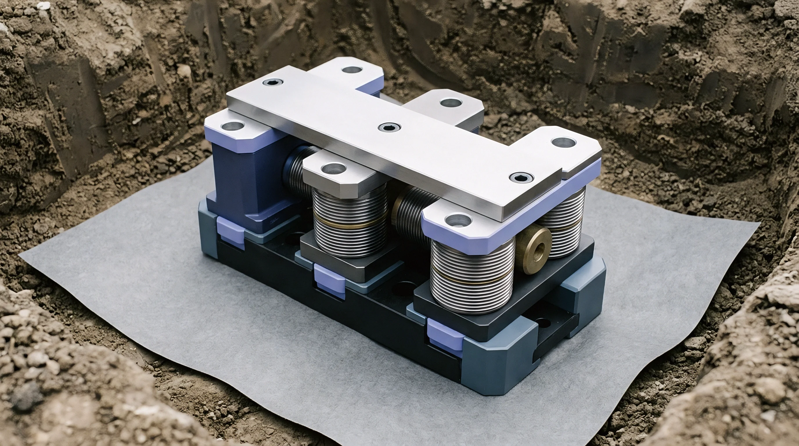
Coupling compounds applied between sensor housings and tool steel eliminate air gaps that dissipate high-frequency stress pulses. Acoustic impedance ~ the product of material density and longitudinal wave velocity ~ governs transmission efficiency across boundaries. AISI D2 tool steel presents an acoustic impedance of 40.6 megarayls, compared to 0.0004 megarayls for ambient air.
Without a fluid or elastomeric couplant, over 99.9 percent of wave energy reflects back into the cylinder shaft rather than entering the transducer housing.
| Material Composition | Peak Resonant Frequency (kHz) | Longitudinal Wave Velocity (m/s) | Acoustic Impedance (MRayl) | Maximum Operating Temperature (C) |
|---|---|---|---|---|
| Lead Zirconate Titanate (PZT-5A) | 150 | 4350 | 33.7 | 200 |
| Lead Titanate (PT) | 220 | 4700 | 31.2 | 350 |
| Lithium Niobate (LiNbO3) | 500 | 6570 | 30.8 | 650 |
| AISI D2 Tool Steel (Die Body) | N/A | 5170 | 40.6 | 150 |
| Polyurethane Anvil (95 Shore A) | N/A | 1680 | 1.85 | 80 |
Benchmarking measurements across solid bleached sulfate samples showed peak signal amplitudes dropping by 14 percent when sensor coupling layer thickness exceeded 15 micrometers. Maintaining consistent mechanical clamping force on sensor housings prevents signal amplitude drift during continuous multi-shift production runs.
Uncalibrated sensor mounting pressure degrades high-frequency voltage output by up to 2.5 decibels per micrometer of coupling air gap.
Physical mounting methods determine signal reproducibility across tool re-sharpening cycles. Magnetic mounts allow quick repositioning but lack contact stiffness, restricting accurate transmission to frequencies below 100 kilohertz. Threaded stud mounting into tapped holes on the die shaft provides rigid acoustic coupling up to 1 megahertz.
Because signal attenuation occurs across mechanical joints inside the die body, sensors must sit within 150 millimeters of the primary scoring zone.
Signal
Voltage transients captured across the die shaft contain millisecond bursts corresponding to localized compression and shear within board plies. A clean score line generates a distinct wave profile with a sharp rise time, a brief peak amplitude envelope, and symmetric ring-down decay. Deviations from this baseline signal point to anomalies in board caliper, moisture content, rule geometry, or anvil cushion clearance.
Processing raw analog signals into usable metrics requires high-speed digital sampling and dedicated time-frequency analysis.
Analog-to-digital converters sampling at 5 to 10 megasamples per second reconstruct stress wave rise times without phase distortion. Signal conditioning units apply analog bandpass filtering between 20 kilohertz and 500 kilohertz to strip out low-frequency press drive vibration and high-frequency electromagnetic noise. The digitized stream then undergoes segmented threshold analysis to isolate individual scoring events from bearing and web tension roller noise.
Time-domain metrics provide immediate indicators of mechanical contact severity. Peak amplitude measures maximum voltage during rule engagement, correlating directly with peak dynamic compressive force. Signal duration records elapsed time from initial threshold crossing to final decay back into background noise.
Ring-down counts track threshold crossings during a single scoring burst, giving a direct measure of internal fiber friction and fracture density.
Time Domain Waveforms in High Speed Scoring
Transient voltage pulses recorded during scoring show immediate amplitude spikes as male rules push board fibers into female channels. Clean scores produce a single, distinct acoustic burst at maximum nip compression. When score depth exceeds the top linerboard’s elastic limit, micro-fractures generate secondary bursts that show up as trailing side-lobes in the time-domain trace.
These secondary peaks mark surface fiber rupture, which causes visible score line cracking during box erecting.
Die cylinder speed directly modulates acoustic burst duration. Running folding boxboard at 300 meters per minute yields a nip contact duration of roughly 1.2 milliseconds for a standard 1.5-millimeter rule width. Increasing web velocity to 450 meters per minute compresses contact duration to 0.8 milliseconds, shifting primary energy to higher frequencies.
Signal processing algorithms must dynamically adjust threshold windows based on real-time speed encoder data to prevent false alarms during acceleration and deceleration.

Spectral Analysis of Internal Fiber Delamination
Frequency distribution charts show energy peaks centered between 120 kilohertz and 280 kilohertz during clean score line deformation. Internal ply delamination ~ essential for low-resistance folding ~ shifts spectral energy into the 150 to 200 kilohertz band as hydrogen bonds yield under shear strain. When top linerboard fibers snap from excessive scoring depth, high-frequency energy spikes above 350 kilohertz dominate the spectrum.
- Top-liner micro-cracking emits transient energy bursts concentrated above 350 kilohertz, indicating high-stress tensile failure of surface bleached fibers.
- Internal matrix crushing generates broad spectrum energy shifts between 80 kilohertz and 140 kilohertz due to compressive collapse of middle recycled plies.
- Deep liner shearing produces asymmetrical wave profiles with prolonged ring-down times exceeding 2.5 milliseconds across the scoring zone.
- Anvil sleeve rebound distortion induces low-frequency modulations below 40 kilohertz that distort baseline voltage stability across consecutive cylinder revolutions.
Fast Fourier Transform processing windowed over 512-microsecond segments isolates failure events along the score line. Short-Time Fourier Transform and Continuous Wavelet Transform methods provide tighter time-frequency localization, allowing engineers to pinpoint board flaws within 0.5 millimeters of web travel. Wavelet coefficients derived from Daubechies mother wavelets isolate short transient spikes obscured by bearing noise.
Setting detection thresholds below baseline press noise triggers continuous false alarms, while setting them above true fiber fracture levels lets cracked scores pass unflagged onto finished pallets. Failing to calibrate attenuation across changing board calipers leaves production unmonitored, leading to full pallet rejections at packaging plants when rigid scores jam high-speed cartoning lines.


Anvil
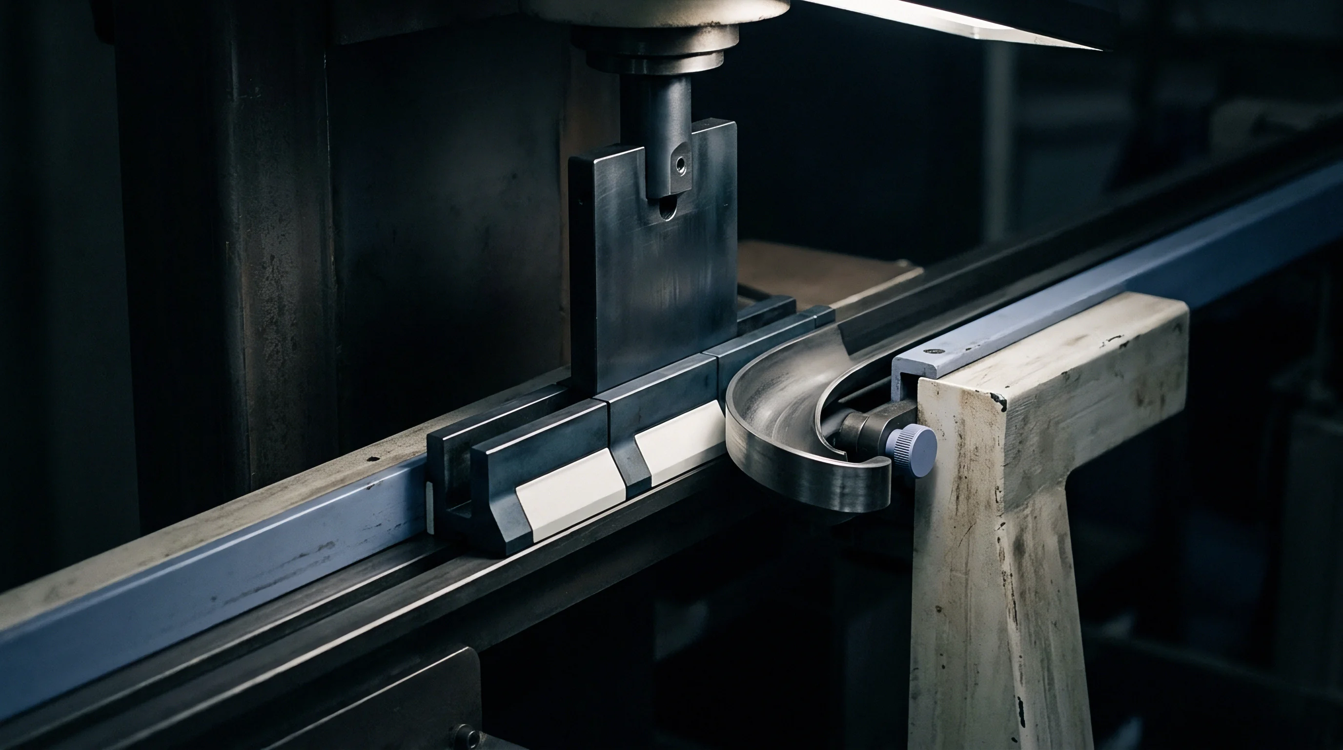
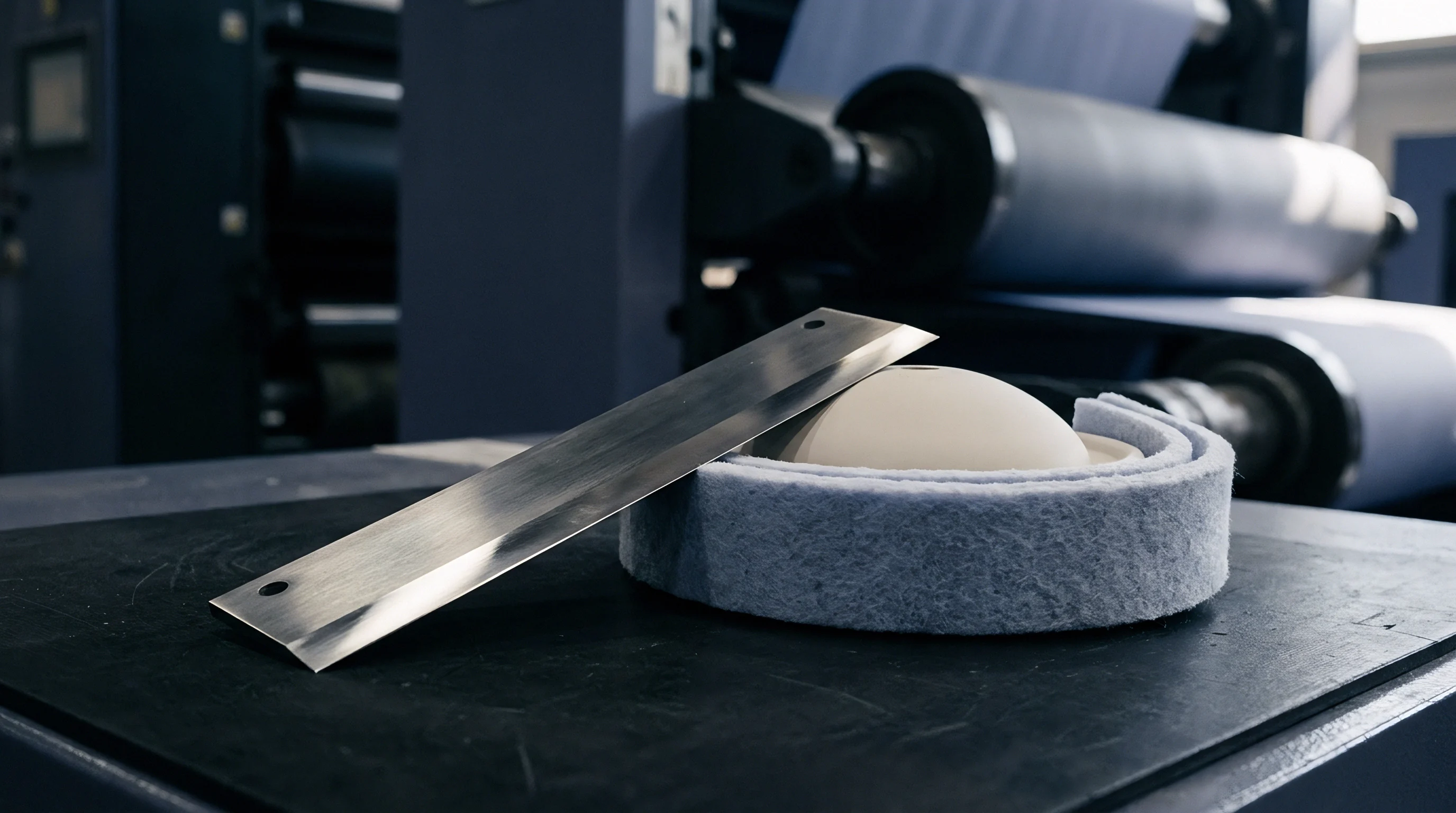
Counter-pressure cylinders coated with synthetic elastomers deform locally, altering stress pulse amplitudes. In rotary die scoring, male steel rules press the paperboard web against polyurethane anvil sleeves or rigid steel female grooves. Polyurethane cushions absorb impact energy while offering enough resistive force to crease the internal board matrix.
As polyurethane sleeves age, mechanical hysteresis and surface cut growth degrade resiliency, altering energy transfer into the web.
Polyurethane anvil sleeves undergo cyclic loading at over 500 compressions per minute on high-speed runs. Indentation memory develops over repeated rotations, reducing effective score depth and shifting contact stress distribution. Sensors on the anvil shaft detect this wear as a gradual drop in peak acoustic amplitude and a broadening in wave arrival times.
Monitoring anvil cushion wear in real time eliminates manual nip impression tests and prevents score line variance across multi-roll production orders.
Female counter-groove selection sets the geometric boundary for score formation. Rigid steel counter-cylinders create sharp, reproducible score creases but demand tight bearing clearance to prevent tool clash. Polyurethane anvils tolerate minor board caliper variations but introduce damping that attenuates high-frequency acoustic emissions.
Understanding the acoustic transfer function of the anvil material is essential for establishing operational monitoring limits.

When Do Transient Amplitude Shifts Indicate Polyurethane Sleeve Breakdown?
Cushion deterioration shows up as a broad reduction in peak voltage output accompanied by prolonged ring-down durations. As polyurethane Shore A hardness drops under thermal buildup, peak dynamic force during scoring decreases, reducing high-frequency acoustic energy reaching the sensors. A continuous drop in peak amplitude exceeding 18 percent over a four-hour window serves as the primary indicator of sleeve fatigue.
Sleeve replacement intervals depend on substrate abrasiveness and nip pressure. Scoring heavy coated recycled board accelerates surface roughness degradation on the sleeve, introducing high-amplitude noise spikes caused by friction rather than fiber deformation. Filtering out friction noise requires tracking spectral energy ratios between the 50 to 100 kilohertz friction band and the 150 to 250 kilohertz fiber yield band.

Female Groove Geometry and Scoring Rule Penetration Depth
Channel dimensions cut into anvil counters determine bending radius and tension distribution across bottom liner fibers. The ratio between male rule width, female channel width, and board caliper dictates the score cracking threshold. Standard practice specifies a female groove width equal to twice the board caliper plus male rule thickness.
Deviations alter mechanical strain rates during scoring, shifting the peak stress wave amplitude recorded by shaft-mounted transducers.
| Board Substrate Grade | Caliper Range (mm) | Penetration Ratio (%) | Peak Stress Wave Amplitude (mV) | Energy Dissipation Coefficient |
|---|---|---|---|---|
| Folding Boxboard (FBB) | 0.35 – 0.55 | 45 – 55 | 420 | 0.28 |
| Solid Bleached Sulfate (SBS) | 0.40 – 0.60 | 40 – 50 | 580 | 0.22 |
| Coated Recycled Board (CRB) | 0.45 – 0.70 | 50 – 60 | 340 | 0.36 |
| Unbleached Kraft Board (SUS) | 0.50 – 0.80 | 35 – 45 | 690 | 0.18 |
| Micro-Flute Corrugated (N-Flute) | 0.80 – 1.20 | 55 – 65 | 290 | 0.44 |
Excessive rule penetration crushes internal board structure, severing fibers and splitting top liners. Insufficient penetration fails to break internal hydrogen bonds, yielding high fold resistance that causes carton bulge during automated filling. Piezoelectric wave monitoring identifies optimal penetration by detecting the exact transition point where internal ply delamination occurs without initiating surface liner cracking.
Standard rotary converting quality parameters specify score stiffness limits within plus or minus 12 percent of nominal target values across full mill roll widths.

Substrate Caliper Variance and Strain Energy Dissipation
Board thickness fluctuations across mill rolls change the compression ratio at fixed cylinder gap settings. A caliper increase of 30 micrometers elevates dynamic nip pressure significantly, raising acoustic wave amplitude and shifting peak frequency distributions upward. Piezoelectric monitoring systems process these wave modifications to calculate real-time caliper deviations without requiring separate optical or mechanical thickness gauges.
Strain energy dissipation varies between virgin fiber and recycled pulp matrices. Virgin bleached softwood kraft fibers absorb higher tensile strains before fracture, emitting short, high-energy acoustic pulses when yielding. Recycled short fibers have lower tensile limits, generating multi-peaked, lower-amplitude emissions as fiber bundles pull apart.
Calibrating signal thresholds to specific furnish compositions prevents false defect readings when switching rolls.
Decision criteria for tool maintenance schedules must integrate both physical anvil sleeve condition and board structural metrics:
- Anvil sleeve surface indentation depth exceeding 0.15 millimeters across the primary scoring track mandates immediate sleeve grinding or axial repositioning.
- Acoustic amplitude signal decay exceeding 20 percent baseline signal level at constant web speed dictates sleeve replacement or temperature re-equilibration.
- Female counter channel wear exceeding 0.08 millimeters lateral opening width requires replacement of the milled counter matrix strip.
- Scoring rule tip radius deformation beyond 0.05 millimeters flat wear spot demands immediate rotary tool cylinder re-tooling.
Observed signal baseline drift is frequently attributed to ambient temperature changes in the press room altering polyurethane durometer, though premature elastomeric fatigue or non-uniform sleeve density across cylinder width can produce the same effect.

Calibration
Standardized reference pulse excitation establishes reproducible sensor sensitivity profiles before transducers are mounted on press shafts. Mechanical shock methods, like pencil lead break testing under ASTM E976 standards, inject repeatable acoustic transients into the cylinder body. Recording the output voltage allows calculating absolute transfer function curves to compensate for signal attenuation caused by shaft geometry, bearing housings, and couplant layers.
Piezoceramic sensors gradually lose sensitivity through thermal cycling, mechanical shock, and depolarization over extended operation. Annual calibration against certified reference transducers maintains measurement accuracy within plus or minus 0.5 decibels across the operating frequency band. Signal amplifiers and analog filtering channels require periodic verification with synthesized signal generators to confirm phase linearity and gain stability across all inputs.
Isolating press vibration is critical for high-speed stress wave analysis. Rotary converting lines running up to 500 meters per minute generate substantial background noise from drive gears, web guide actuators, and vacuum transfer rolls. Digital bandpass filters and adaptive noise cancellation algorithms isolate discrete scoring stress waves from continuous machinery noise.

Simulated Acoustic Emission Baseline Benchmarking
Snapping fine graphite leads against die steel injects precise transient strain energy pulses into the tool assembly. A 0.5-millimeter 2H pencil lead broken at a 30-degree contact angle under ISO 12716 procedures generates an acoustic pulse with a rise time under 0.5 microseconds. Capturing this reference burst establishes baseline attenuation between the scoring nip and the transducer mounting point.
Attenuation mapping across a 1.6-meter rotary scoring cylinder reveals signal amplitude drops of up to 8 decibels at scoring positions far from journal-mounted sensors. Arrays must deploy multiple piezoceramic elements spaced axially along the cylinder housing or use calibrated digital amplification channels mapped to web lanes to maintain uniform defect detection across the full web width.

Noise Suppression in High Speeds and Bearing Rumble Filter Schemes
Gear vibration generates continuous low-frequency voltage disturbances below 50 kilohertz. High-pass analog filtering strips these components out before signal amplification, preventing amplifier saturation and preserving signal-to-noise ratios. Bearing passage frequencies, calculated from shaft rotation speeds and bearing dimensions, generate discrete spectral lines that adaptive notch filters eliminate in real time.
Cross-correlation analysis comparing active die sensor signals against reference accelerometers mounted on non-contact press frames eliminates environmental vibration from adjacent printing units or shop floor traffic. Signal threshold algorithms process only coherent transient events that correlate precisely with male rule engagement timing signals from optical encoders on the die shaft end.
The standard zeroing procedure for piezoceramic sensor setups follows a sequential technical progression:
- Clean die shaft transducer mounting surfaces with isopropyl alcohol to remove oil, greases, and anti-corrosion residues.
- Apply a 0.05-millimeter layer of high-viscosity silicone acoustic couplant to the sensor face before clamping.
- Torque sensor mounting studs to 2.5 Newton-meters using a calibrated torque wrench to ensure reproducible mechanical coupling stress.
- Execute five pencil lead break reference pulses within 20 millimeters of the primary scoring zone to establish baseline transfer gain.
- Normalize data acquisition hardware channel gain registers to achieve 1.0 Volt peak-to-peak output for standard reference pulses.
Piezoelectric transducers operating within rotary converting environments must maintain flat frequency response characteristics within plus or minus 3 decibels across their specified operating range.
Quality assurance specifications derived from packaging standards require online stress wave monitoring equipment to undergo formal re-verification per ISO 12716 every 2000 operating hours or following any die cylinder crash. Failing to document this calibration cycle invalidates supplier liability claims regarding score line cracking on delivered carton lots.


Yield
Continuous inline structural monitoring transforms die gap maintenance from reactive stop-and-measure routines into dynamic closed-loop positioning. Rotary scoring units with motorized eccentric bearing blocks use real-time stress wave amplitude telemetry to adjust cylinder clearance automatically during operation. Correcting clearance in response to thermal shaft expansion or web caliper shifts keeps score line depth consistent, eliminating carton scrap caused by under-scoring or over-scoring.
Manual quality verification relies on destructive pull-tests and score stiffness measurements conducted on sample sheets pulled from delivery stacks. This offline approach lets hundreds of defective cartons run through the press before an operator detects cracking or poor foldability. Inline stress wave monitoring evaluates every score line across every revolution, identifying process drift within milliseconds and enabling instant servo-actuated gap corrections.
Real Time Feedback Control and Automated Gap Adjustment
Motorized eccentric bearing blocks receive voltage amplitude telemetry to adjust cylinder clearance in five-micrometer increments. When peak stress wave amplitude exceeds upper control limits ~ indicating excessive rule penetration and imminent top liner cracking ~ the system signals servo actuators to open the gap. When amplitude falls below lower limits ~ indicating incomplete internal ply delamination ~ the system decreases clearance to restore score depth.
| Metric Category | Manual Quality Sampling | Piezoelectric Online Wave Analysis | Variance Impact per 1000 Units (EUR) |
|---|---|---|---|
| Make-Ready Substrate Waste (kg) | 1450 | 380 | -1.85 |
| Unscheduled Press Downtime (Hours) | 42 | 8 | -2.40 |
| Customer Carton Rejection Rate (%) | 0.38 | 0.02 | -4.15 |
| Anvil Cushion Service Life (Revolutions) | 12,000,000 | 18,500,000 | -0.65 |
| Total Landed Defect Expense (EUR) | 245,000 | 28,500 | -9.05 |
Automated control loops integrate web speed feed-forward signals to compensate for dynamic press deflection. High-speed rotary dies experience cylinder separation forces exceeding 50 kilonewtons at maximum web speeds, causing mechanical flexure in die journals and press frames. Piezoelectric wave monitoring detects the resulting score depth variation and instructs motorized bearing blocks to increase preload force during high-speed runs.
Closed-loop control systems enforce absolute movement boundaries to prevent tool clash during web breaks. If tension sensors register a break, the monitoring unit overrides automated gap adjustments, immediately signaling hydraulic lift cylinders to open the die gap by 3.0 millimeters to protect scoring rules and anvil sleeves from metal-to-metal contact.

Economic Analysis of Online Stress Wave Monitoring
Calculating financial returns for sensor installation requires balancing hardware costs against scrap reduction across high-volume production schedules. Capital expenses for a four-channel piezoelectric monitoring system ~ including high-speed data acquisition hardware, shaft slip rings, and closed-loop control software ~ typically total 45,000 EUR per converting line. For high-volume packaging converters processing 50 million cartons annually, scrap reduction alone yields a payback period under seven months.
Operating rotary die scoring units with optimized nip clearance minimizes unnecessary impact stress on rule edges and polyurethane anvils. Polyurethane anvil sleeve service life increases by up to 50 percent under stress wave feedback control, reducing re-grinding expenses and setup downtime.
Sourcing desks and packaging engineers pricing high-volume carton runs should evaluate whether a converter operates online acoustic emission monitoring, as lines utilizing real-time stress wave feedback achieve lower spoilage allowances and permit tighter score stiffness tolerances across high-speed packaging applications.
Score crease stiffness remains consistent when dynamic nip force matches the elastic yield stress of the middle board plies without exceeding the ultimate tensile strength of the outer linerboard.