Calculating Matrix Depth Ratios for Co-Extruded Film Laminates under Pressure
Matrix depth ratios dictate counter-die selection by balancing polymer yield strain against substrate compaction to preserve layer integrity under pressure.

Compliance
Multi-layer polymeric structures laminated to fibrous board substrates exhibit complex stress-strain behavior under compressive load. Applied pressure does not distribute uniformly through a co-extruded packaging film’s cross-section; each layer responds according to its own viscoelastic modulus, Poisson ratio, and plastic yield point. Under load, these polymeric layers compress unevenly.
As a laminating film moves through a high-pressure nip roll or hits an embossing die, localized compression drives softer skin polymers to deform laterally, whereas stiffer internal barrier cores resist dimensional change until reaching their ultimate yield point.
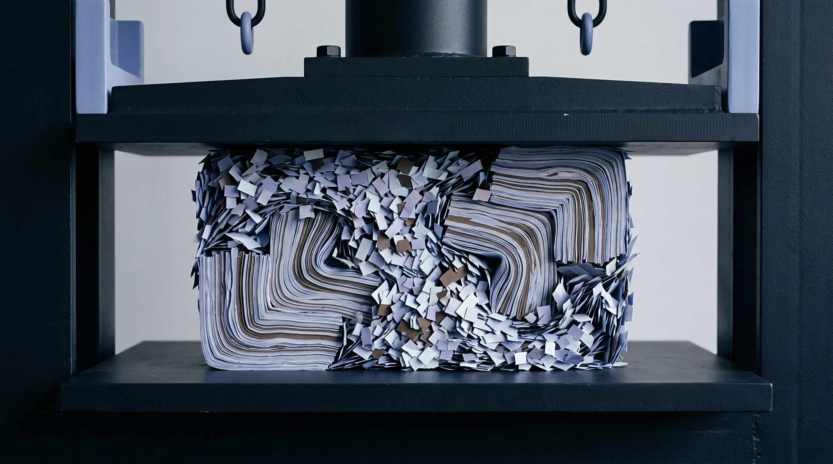
Total deformation in a co-extruded film laminate reflects the combined caliper reduction of its synthetic skin layers, functional tie layers, barrier cores, and the underlying cellulose fiber network. Solid bleached sulfate board compresses under load, losing ten to thirty percent of its bulk thickness at standard nip pressures. When the material exits the nip zone and pressure drops, cellulose fibers recover partially, while compressed polymer layers show time-dependent elastic spring-back alongside permanent plastic deformation.
Analyzing the mechanical strain profile across each co-extruded layer determines plastic yield thresholds.

Substrate Compaction Dynamics
Paperboard compaction directly dictates the effective pressure that reaches an extruded film layer. Solid bleached sulfate board, folding boxboard, and recycled coated recycled board possess distinct initial densities and void ratios. Applied pressure between 2.0 MPa and 12.0 MPa collapses paperboard fibers into interstitial voids, absorbing a large portion of the compressive energy.
How deep deformation extends into the film layer depends on the ratio between the board’s bulk modulus and the shear modulus of the adjacent polymer layer.
A soft board substrate allows the film layer to sink into the fiber bed during high-pressure embossing or creasing operations, altering local matrix geometry and thinning the film along the impression’s perimeter. Conversely, a high-density board substrate acts like a rigid anvil. Here, the applied force concentrates inside the co-extruded film structure, driving severe lateral flow in low-density polyethylene skin layers and potentially shearing brittle ethylene vinyl alcohol barrier layers.
Viscoelastic Modulus Contrast across Polymer Layers
Co-extruded films combine materials with widely disparate mechanical properties. A typical five-layer barrier film features outer low-density polyethylene skin layers, maleic anhydride modified tie layers, and a central ethylene vinyl alcohol core layer. Under high nip pressure, the ratio of elastic moduli between adjacent polymer layers determines the degree of interfacial shear stress generated during compression, driving film shear.
| Polymer Layer Identification | Density Range (g/cm³) | Compressive Modulus (MPa) | Poisson Ratio | Plastic Yield Stress (MPa) |
|---|---|---|---|---|
| Low-Density Polyethylene (LDPE) Outer Skin | 0.918 – 0.924 | 220 – 350 | 0.45 | 8.5 – 11.0 |
| Linear Low-Density Polyethylene (LLDPE) Sealant | 0.916 – 0.926 | 300 – 450 | 0.44 | 10.0 – 13.5 |
| Maleic Anhydride Modified Tie Layer | 0.920 – 0.935 | 380 – 520 | 0.42 | 12.0 – 15.0 |
| Ethylene Vinyl Alcohol (EVOH, 32 mol% ethylene) | 1.170 – 1.200 | 2100 – 2800 | 0.33 | 45.0 – 62.0 |
| Biaxially Oriented Polyamide (BOPA) Structural Core | 1.140 – 1.160 | 1800 – 2400 | 0.36 | 50.0 – 70.0 |
When applied pressure exceeds the plastic yield stress of the low-density polyethylene skin layer but remains below that of the ethylene vinyl alcohol core, differential yield occurs. The skin deforms plastically, thinning locally, while the barrier core undergoes purely elastic strain and returns toward its original thickness once pressure releases. This differential response leaves localized residual stresses at the polymer interface, which can induce film curl, edge haze, or delamination over time.
The mechanical response of a co-extruded film laminate under compressive pressure depends directly on the ratio of elastic moduli between adjacent polymer layers and the compaction behavior of the underlying cellulose substrate.
Failure modes emerge during conversion if compressive stress distributions are miscalculated. In conversion trials, an immediate elastic spring-back of thirty percent occurs in low-density polyethylene skins as soon as the load releases. Identifying these mechanisms early prevents costly tooling errors and lost production time.
- Layer Modulus Mismatch Material deformation concentrates in soft low-density skins, generating severe shear stress at the interface with rigid barrier cores during nip passage.
- Pin-Hole Fracture Brittle ethylene vinyl alcohol layers crack under localized pressure peaks when the underlying board substrate reaches maximum compaction density.
- Lateral Resin Displacement Low-density polyethylene skins flow outward from high-pressure embossing lines, thinning the sealant layer along creasing channels.
- Interfacial Delamination Residual elastic stress differences between stretched tie layers and rigid core layers overcome chemical bond strength after embossing.
Whether high-density tie-layer formulations can prevent micro-delamination at pressures above twenty megapascals remains an open question for film formers.

Ratio
Calculating deformation metrics for multi-layer co-extrusions requires account of compressive strain across every constituent polymer layer. The matrix depth ratio defines how permanent indentation depth in the laminate relates to the uncompressed thickness of the film-board combination. Setting accurate depth ratios ensures scoring, creasing, and embossing dies yield crisp tactile lines without puncturing barrier layers or crushing paperboard fibers to structural failure.
Matrix depth ratios are calculated from baseline calipers measured with a micrometer. Total initial laminate thickness equals uncompressed board thickness plus total co-extruded film thickness. Applying pressure induces vertical strain as the male die or nip roll penetrates the material surface, and the resulting depth ratio captures both plastic compression under load and elastic recovery after tool withdrawal.
Derivation of Compressive Strain Coefficients
Deriving the matrix depth ratio begins with layer-by-layer compressive strain equations. Let total uncompressed laminate thickness be baseline caliper T_0, where T_0 equals the sum of individual polymer layer thicknesses t_i plus the paperboard substrate caliper t_sb. Applied pressure P generates vertical displacement d under steady-state dwell conditions.
The nominal matrix depth ratio R_m is the permanent indentation depth d_m divided by initial uncompressed film thickness t_f.
To account for multi-layer viscoelastic behavior, each layer receives an empirical compressive strain coefficient alpha_i that integrates elastic modulus E_i, Poisson ratio nu_i, and strain hardening exponent n_i. Under applied pressure P, vertical strain epsilon_i for layer i follows the power-law relationship:
epsilon_i = ( P / E_i )^(1 / n_i)
The unrecovered plastic indentation depth within the film layer d_fp is found by subtracting elastic recovery strain epsilon_e from total peak compressive strain epsilon_p across all film layers:
d_fp = sum( t_i ( epsilon_p,i – epsilon_e,i ) )
Paperboard substrate deformation d_sb involves both elastic compression and irreversible micro-fiber collapse. The total permanent matrix depth d_m combines plastic film displacement d_fp and permanent substrate impression d_sb, giving the operational matrix depth ratio formula:
R_m = d_m / t_f = ( d_fp + d_sb ) / sum( t_i )
| Board Caliper (µm) | Film Caliper (µm) | Film Layer Structure | Applied Pressure (MPa) | Peak Indentation (µm) | Final Matrix Depth Ratio (R_m) |
|---|---|---|---|---|---|
| 300 (SBS) | 35 | LDPE / Tie / EVOH / Tie / LDPE | 4.0 | 42 | 0.48 |
| 300 (SBS) | 35 | LDPE / Tie / EVOH / Tie / LDPE | 8.0 | 68 | 0.82 |
| 300 (SBS) | 35 | LDPE / Tie / EVOH / Tie / LDPE | 12.0 | 89 | 1.14 |
| 450 (FBB) | 50 | LLDPE / Tie / BOPA / Tie / LLDPE | 4.0 | 55 | 0.42 |
| 450 (FBB) | 50 | LLDPE / Tie / BOPA / Tie / LLDPE | 8.0 | 92 | 0.76 |
| 450 (FBB) | 50 | LLDPE / Tie / BOPA / Tie / LLDPE | 12.0 | 128 | 1.08 |
| 600 (CRB) | 75 | HDPE / LLDPE / EVOH / LLDPE / HDPE | 4.0 | 78 | 0.36 |
| 600 (CRB) | 75 | HDPE / LLDPE / EVOH / LLDPE / HDPE | 8.0 | 135 | 0.68 |
| 600 (CRB) | 75 | HDPE / LLDPE / EVOH / LLDPE / HDPE | 12.0 | 184 | 0.96 |
Worked Calculation for Five Layer Barrier Packaging
Consider a practical converting scenario with a 450 micrometer folding boxboard substrate laminated to a 50 micrometer five-layer co-extruded barrier film. The film structure comprises outer LLDPE skin layers (15 micrometers each), maleic anhydride tie layers (3 micrometers each), and a central EVOH barrier core (14 micrometers). The converter sets an embossing die pressure of 8.5 MPa with a dwell time of 40 milliseconds at 22 degrees Celsius.
First, establish individual layer properties. LLDPE has an elastic modulus of 350 MPa and plastic yield stress of 11.0 MPa; the tie layer has a modulus of 450 MPa; EVOH has an elastic modulus of 2400 MPa and yield stress of 52.0 MPa. Under 8.5 MPa pressure, applied stress exceeds the yield stress of the LLDPE skins while remaining below that of the EVOH core.
Elastic spring-back in EVOH equals ninety-two percent of its strain, whereas LLDPE retains seventy percent of its peak compressive displacement as permanent plastic deformation.
Second, calculate peak vertical displacement within the polymer structure. Peak film strain under 8.5 MPa reaches 0.22 (22 percent of total film thickness), which means an absolute displacement of 11.0 micrometers during peak tool engagement. Permanent thinning in the LLDPE skins accounts for 8.5 micrometers, tie layers contribute 0.9 micrometers, and the EVOH core undergoes 1.6 micrometers of elastic compression ~ recovering 1.47 micrometers upon release to leave just 0.13 micrometers of permanent dimensional change.
Third, integrate paperboard substrate collapse. The 450 micrometer folding boxboard compresses by 82.0 micrometers under 8.5 MPa pressure. Caliper recovery tests confirm the board bounces back by 55.0 micrometers, leaving a permanent board impression depth d_sb of 27.0 micrometers.
Total permanent matrix depth d_m equals permanent film displacement (8.5 + 0.9 + 0.13 = 9.53 micrometers) plus permanent board displacement (27.0 micrometers), giving d_m = 36.53 micrometers.
Fourth, compute the matrix depth ratio R_m. Dividing permanent matrix depth (36.53 micrometers) by initial film caliper (50.0 micrometers) gives an operational matrix depth ratio of 0.7306. A ratio around 0.73 indicates optimal crease definition without risking barrier shear or pin-holing in the central EVOH layer.
An operational matrix depth ratio of 0.73 achieved under 8.5 MPa pressure on a 450 micrometer folding boxboard laminate ensures clear impression geometry while keeping ethylene vinyl alcohol plastic strain below two percent.
The quantitative procedure for verifying matrix depth ratios on production lines follows a precise sequence.
- Measure baseline thickness of the uncompressed film-board laminate with a precision micrometer under ISO 534 standard contact pressure.
- Section an uncompressed control sample and use optical microscopy to record individual co-extruded polymer layer thicknesses.
- Execute an embossing or creasing pass at target line speed, pressure, and temperature.
- Extract sample specimens post-press and condition them for twenty-four hours at 23 degrees Celsius and 50 percent relative humidity per ISO 187.
- Measure permanent impression depth across the center of the creasing channel using a non-contact optical profilometer.
- Calculate the final matrix depth ratio by dividing measured impression depth by initial uncompressed film thickness.
- Compare the calculated ratio against critical yield thresholds to adjust tooling die clearance before full commercial production.
Thicker skin layers always absorb localized pressure peaks before compressive stress reaches the internal barrier core.
Displacement
When extreme nip pressures act on a co-extruded barrier film laminate, soft polyolefin layers undergo localized lateral movement. This lateral resin displacement shifts polymer mass away from high-compression zones into adjacent uncompressed valleys. Under high hydrostatic pressure, low-density polyethylene skin layers behave almost like incompressible fluids, displacing horizontally whenever vertical clearance drops below critical limits.
This flow dynamic becomes hazardous along sharp creasing edges or narrow embossing dies. As low-density polyethylene flows horizontally, local film thickness drops rapidly along the compression shoulder. Constrained between migrating skin layers, the central barrier core experiences severe tensile and bending forces that threaten packaging shelf life.
If lateral displacement thins the outer skin by more than fifty percent, the core loses its protective cushioning and risks shear fracture from direct contact with hard substrate fibers.
Barrier Integrity Loss under Hydrostatic Compression
Barrier materials such as ethylene vinyl alcohol and biaxially oriented polyamide exhibit high tensile moduli but low elongation at break under compressive shear. When subjected to localized pressure peaks during web processing, these rigid layers cannot flow laterally like surrounding polyolefin skins, accommodating deformation instead through microscopic necking or micro-cracking.
A micro-crack in an ethylene vinyl alcohol layer measuring less than two micrometers in width can increase oxygen transmission rates across the package by up to two orders of magnitude. The barrier performance of the entire film is compromised even when outer polyolefin skins appear visually intact. Non-destructive testing via helium leak detection or optical oxygen sensor spots reveals severe performance loss in packages embossed with excessively high matrix depth ratios.
Microscopic Layer Redistribution and Lateral Flow
Cross-sectional microscopy of deformed co-extrusions clearly demonstrates layer thinning. Under a matrix depth ratio exceeding 1.10, the local skin-to-core thickness ratio changes dramatically: while uncompressed regions maintain a nominal 30:6:28:6:30 layer percentage distribution, high-pressure embossing lines can shift that distribution to 10:4:28:4:10 inside the compressed creasing channel.
The skin layers lose two-thirds of their thickness while the rigid central core retains nearly all of its original caliper. This severe localized thinning forces tie layers into extreme elongation strain. Exceeding tie-layer elongation limits triggers interfacial cleavage, causing the outer low-density polyethylene skin to separate from the barrier core and form air pockets along the crease line.
During hot-fill or retort operations, these air pockets expand, leading to macro-delamination and total seal failure.
Laminate failure during high-pressure embossing stems from lateral polyolefin resin flow that strips protective skin thickness from rigid barrier cores.
Incorrect depth ratio calculations lead to catastrophic oxygen barrier degradation, forcing complete product recalls when vacuum packs lose seal integrity.
Counterpart
Selecting matching female scoring channels and embossing matrices requires translating calculated film yield behavior into exact tooling dimensions. Converting equipment relies on counter-die channels to form precise scores and creases in film-laminated board, where tooling depth dictates fold accuracy. Both the width and depth of the female channel must accommodate displaced board fibers and the plastically deformed film layer without creating mechanical pinch points.
Male-to-female die clearances are specified based on calculated layer compaction factors. If a female channel is too narrow, the co-extruded film gets pinched between the male rule and the channel wall. Channel width provides necessary strain relief; pinching exerts extreme shear stress on outer film layers, stripping polymer off the board.
Conversely, an overly wide channel fails to produce clean fold definition, resulting in weak crease lines and erratic folding resistance on high-speed cartoners.
Matrix Channel Dimensions and Scoring Geometry
Designing creasing tooling for co-extruded laminates requires adjusting standard cartonboard tooling formulas to account for film elasticity. Standard creasing rules for unlaminated board set female channel width W equal to board thickness t_sb multiplied by 1.5, plus male rule thickness t_mr. For co-extruded laminates, this formula must incorporate a film displacement factor delta_f based on the matrix depth ratio R_m.
The corrected channel width equation for co-extruded film laminates is formulated as:
W = t_mr + 1.6 t_sb + 2.0 t_f ( 1 + R_m )
Female channel depth D must exceed the combined thickness of compressed board and displaced film to prevent bottoming out, which turns controlled creasing into destructive compression that crushes fibers and tears barrier cores. Channel depth D is calculated as:
D = 1.1 ( t_sb_compressed + d_fp )
| Total Laminate Caliper (µm) | Film Caliper (µm) | Male Rule Thickness (mm) | Target Depth Ratio (R_m) | Calculated Channel Width (mm) | Recommended Channel Depth (mm) |
|---|---|---|---|---|---|
| 335 | 35 | 0.71 | 0.50 | 1.30 | 0.35 |
| 380 | 50 | 0.71 | 0.70 | 1.48 | 0.40 |
| 500 | 50 | 1.05 | 0.75 | 1.97 | 0.50 |
| 675 | 75 | 1.42 | 0.80 | 2.62 | 0.65 |
| 875 | 100 | 1.42 | 0.90 | 3.05 | 0.85 |
Which Creasing Channel Prevents Substrate Fracture under High Compression?
Channel selection must balance score sharpness against layer fracture risk. Phenolic resin channels, vulcanized rubber matrix strips, and milled steel counter-dies each exert different reactive forces on the film laminate. Phenolic channels provide rigid wall support that yields sharp fold edges, though they require precise alignment to avoid film tearing.
Rubber-based matrices yield slightly under load, distributing peak stress to protect brittle barrier cores at the expense of minor crease relaxation.
Web speed alters dwell duration. Fast rotary die-cutting lines operating at three hundred meters per minute reduce load dwell time to under five milliseconds, making polymer relaxation times critical. These brief dwell times increase effective polymer stiffness, shifting low-density polyethylene from ductile plastic flow toward elastic behavior.
As a result, tooling clearance on high-speed rotary converters must be widened by five to ten percent compared to lower-speed flatbed platen presses.
A systematic tooling verification checklist protects production runs from die-induced failure.
- Channel Width Verification Confirm that female matrix channel width accounts for double film thickness plus substrate displacement under full compressive load.
- Counter-Die Hardness Matching Match matrix shore hardness to line speed, selecting semi-rigid polymers for high-speed rotary lines to cushion impact shear.
- Male Rule Radius Inspection Ensure male creasing rules feature rounded working edges with a minimum radius of 0.35 mm to prevent localized film cutting.
- Position Alignment Audit Perform laser alignment checks between male rules and female matrix channels to eliminate asymmetric shearing forces along crease walls.
Film splitting is frequently attributed strictly to substrate moisture falling below pressroom specification.
Dossier
Translating theoretical film yield calculations into binding purchasing contracts protects converting operations from costly material rejections. Specifications for co-extruded barrier film laminates must set strict tolerances for layer thickness variations, adhesive coat weights, and substrate bulk uniformity. Even a minor shift in baseline skin thickness alters matrix depth ratios, throwing off creasing performance across an entire converting run.
Because resin density dictates strain recovery, procurement dossiers should mandate layer-by-layer caliper tolerances rather than total film thickness alone. A supplier delivering a nominal 50 micrometer barrier film under a plus-or-minus ten percent total thickness specification could supply material where the critical EVOH barrier core varies by thirty percent. Such variance alters layer strain dynamics under pressure, causing unexpected pin-holing or score cracking during production runs.
Quality Assurance Tolerances for Film Compression
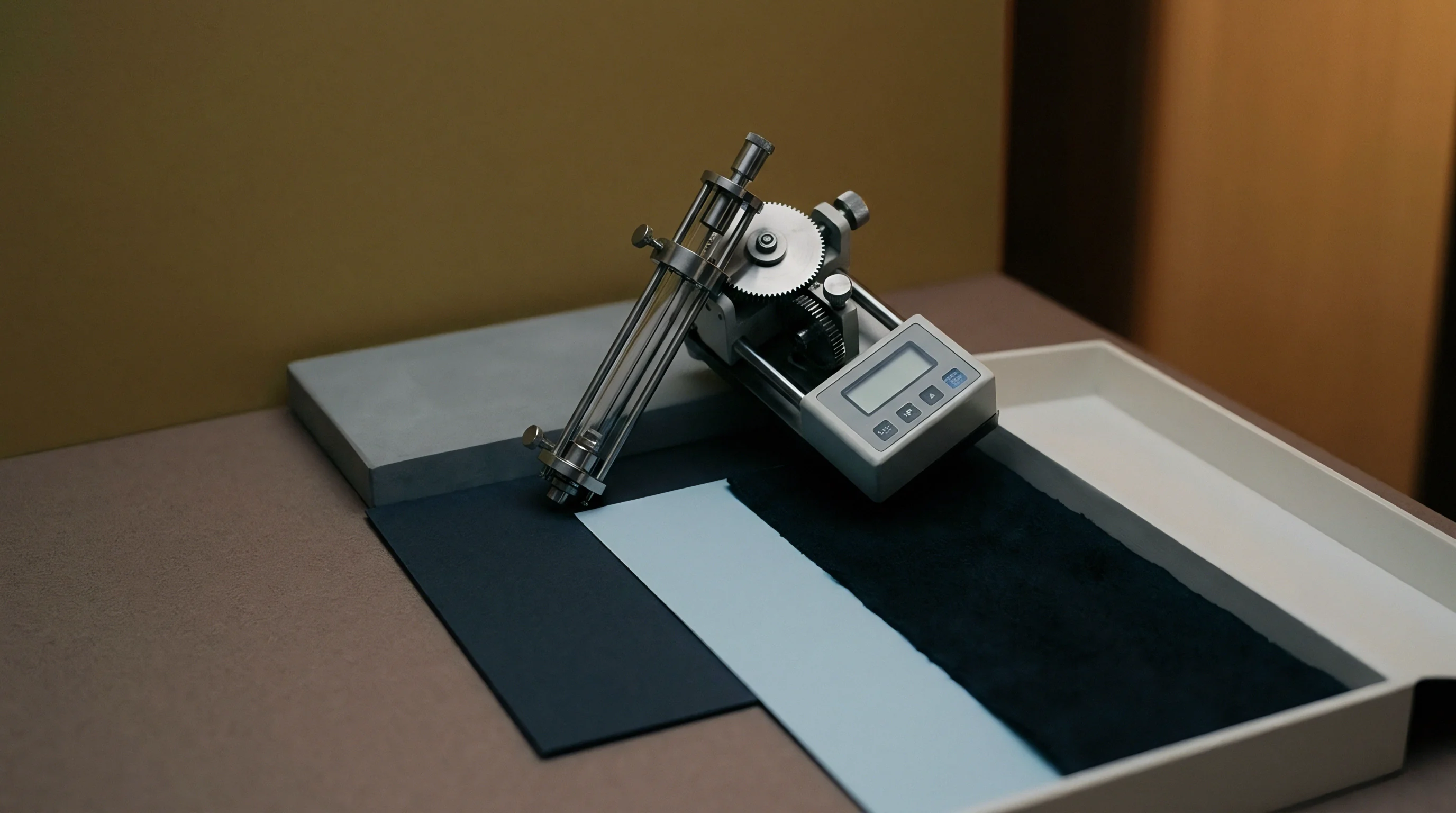
Incoming quality control procedures must audit plastic deformation compliance. Standard testing protocols subject batch samples to bench compression tests using ISO 534 thickness micrometers modified with hemispherical press anvils. Recorded load-displacement curves confirm whether plastic yield points meet pre-approved converter specifications.
Excessive elastic recovery in material batches forces converters to increase die pressure, which accelerates tooling wear and raises the risk of fiber fracture. Clear contract language should define acceptable matrix depth ratio bands for specified press settings. Rejecting non-compliant materials before press mounting avoids unnecessary downtime and wasted converter stock.

Commercial Waste Arithmetic and EPR Modulations
Calculating the landed cost of a laminated packaging run requires factoring in scrap rates generated during matrix depth setup. Make-ready waste on a complex barrier carton run typically averages three to five percent of total order volume. Flawed matrix depth ratio calculations can drive make-ready waste past fifteen percent, wiping out profit margins on custom runs.
Modern packaging regulations introduce modulated Extended Producer Responsibility (EPR) fees based on material recyclability grades. Co-extruded film laminates face severe financial penalties if film content exceeds five percent of total package weight or if layers fail to separate during pulp repulping trials. Specifying film compositions that achieve target matrix depth ratios at thinner calipers directly lowers EPR fee assessments per thousand units.
Maintaining co-extruded film content below five percent of total carton weight avoids maximum Extended Producer Responsibility fee surcharges while supporting repulpability compliance.
Optimizing matrix depth ratios achieves thin-gauge film functionality ~ reducing total polymer usage and shipping weight while keeping the package compliant with international recyclability guidelines.
Standard convertor supply agreements reject liability for layer delamination if line speed exceeds contractually specified nip dwell limits.