Quantitative Correlation between in Line Ultrasonic Crease Attenuation and Box Compression Retention
Inline ultrasonic attenuation across score lines provides real-time prediction of box compression strength retention without destructive testing.


Signal
High-frequency acoustic energy travelling across a creased paperboard sheet encounters structural discontinuities that dissipate mechanical wave amplitude. When corrugated board moves through a high-speed converting line, rotary scoring tools compress the combined board along defined lines to form box hinges. This localized deformation crushes internal fluting and disrupts fiber-to-fiber bonding within inner and outer linerboards.
Transverse ultrasonic waves directed through the score line experience scattering and absorption directly proportional to the physical disruption of the fiber matrix. Measuring this attenuation in real time provides an immediate physical proxy for damage inflicted during scoring.
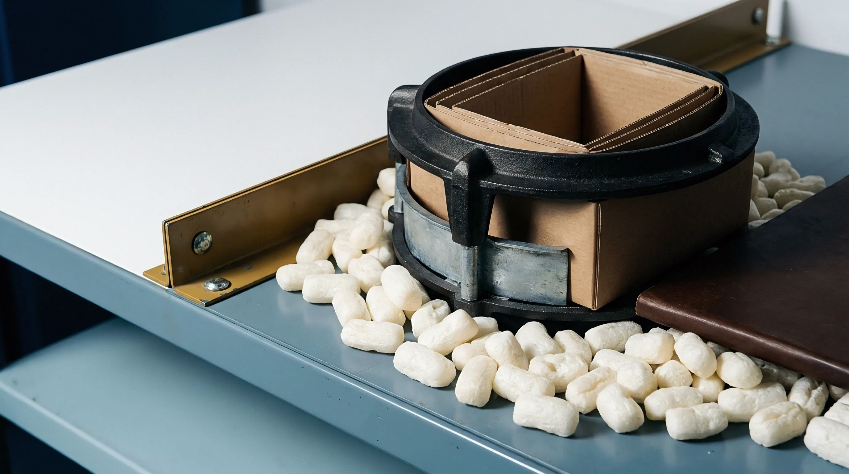
Pitch-Catch Wave Mechanics across Corrugated Scores
Transverse piezoelectric emitters output sound pulses between 40 kHz and 500 kHz that pass through the linerboard thickness toward an opposing receiver. Uncreased combined board presents a uniform density profile with predictable acoustic transmission velocity and signal attenuation. When scoring wheels indent the board surface, densification of paper fibers initially increases sound transmission velocity through the crushed region.
Wave amplitude drops fast. Beyond a critical compression threshold, micro-cracking within outer liner fibers and delamination between paperboard plies introduce acoustic impedance boundaries.
Acoustic waves encounter air-filled micro-voids created by fiber bond failure within the crease. Air has an acoustic impedance orders of magnitude lower than dense cellulose fibers. This impedance mismatch causes partial reflection and phase scattering of transmitted ultrasonic pulses.
The decibel drop in peak-to-peak signal amplitude serves as a direct indicator of structural degradation within the crease zone.
A 12 dB drop in transverse ultrasonic amplitude across a double-wall score line correlates with a 23 percent loss in score line compression resistance at 50 percent relative humidity.

Acoustic Impedance Discontinuities from Inter-Fiber Fracture
Densification of cellulose plies during mechanical indentation alters local density and elastic modulus values within the score region. Pitch-catch transducer pairs positioned on opposing sides of the crease line continuously record wave transmission spectra as board sheets run at speeds exceeding 300 meters per minute. The relationship between scoring tool penetration depth, local caliper reduction, and ultrasonic attenuation follows a non-linear trajectory.
| Crease Penetration Depth (mm) | Anvil Gap (mm) | Acoustic Attenuation (dB) | Transverse Wave Speed (m/s) | Score Residual Caliper Ratio (%) |
|---|---|---|---|---|
| 0.80 | 3.40 | 2.1 | 1850 | 88.2 |
| 1.20 | 3.00 | 4.8 | 1920 | 76.5 |
| 1.60 | 2.60 | 8.5 | 1780 | 63.1 |
| 2.00 | 2.20 | 14.2 | 1540 | 51.4 |
| 2.40 | 1.80 | 21.6 | 1210 | 40.8 |
Initial tool contact causes moderate densification that elevates wave velocity while attenuation remains low. As tool penetration exceeds 1.5 millimeters, shear stresses within the linerboard trigger internal ply separation. Inter-fiber bonds fracture.
Attenuation accelerates rapidly as internal delamination voids multiply. Signal decay indicates fracture. Monitoring signal drop across specific frequency bands isolates fiber fracture from simple web compaction, giving converting operators explicit quantitative data before visible surface cracking appears.
Tooling vendors routinely claim that score attenuation stems entirely from moisture variance rather than mechanical anvil penetration.


Matrix
Corrugated paperboard consists of orthotropic fiber networks arranged in stratified liner and fluting layers. The structural response of this fiber web during rotary creasing determines both folding performance and final container stacking strength. Creasing tools force the planar sheet into a contoured female channel, subjecting outer liner fibers to bending tension while internal plies undergo severe shear and compressive stress.
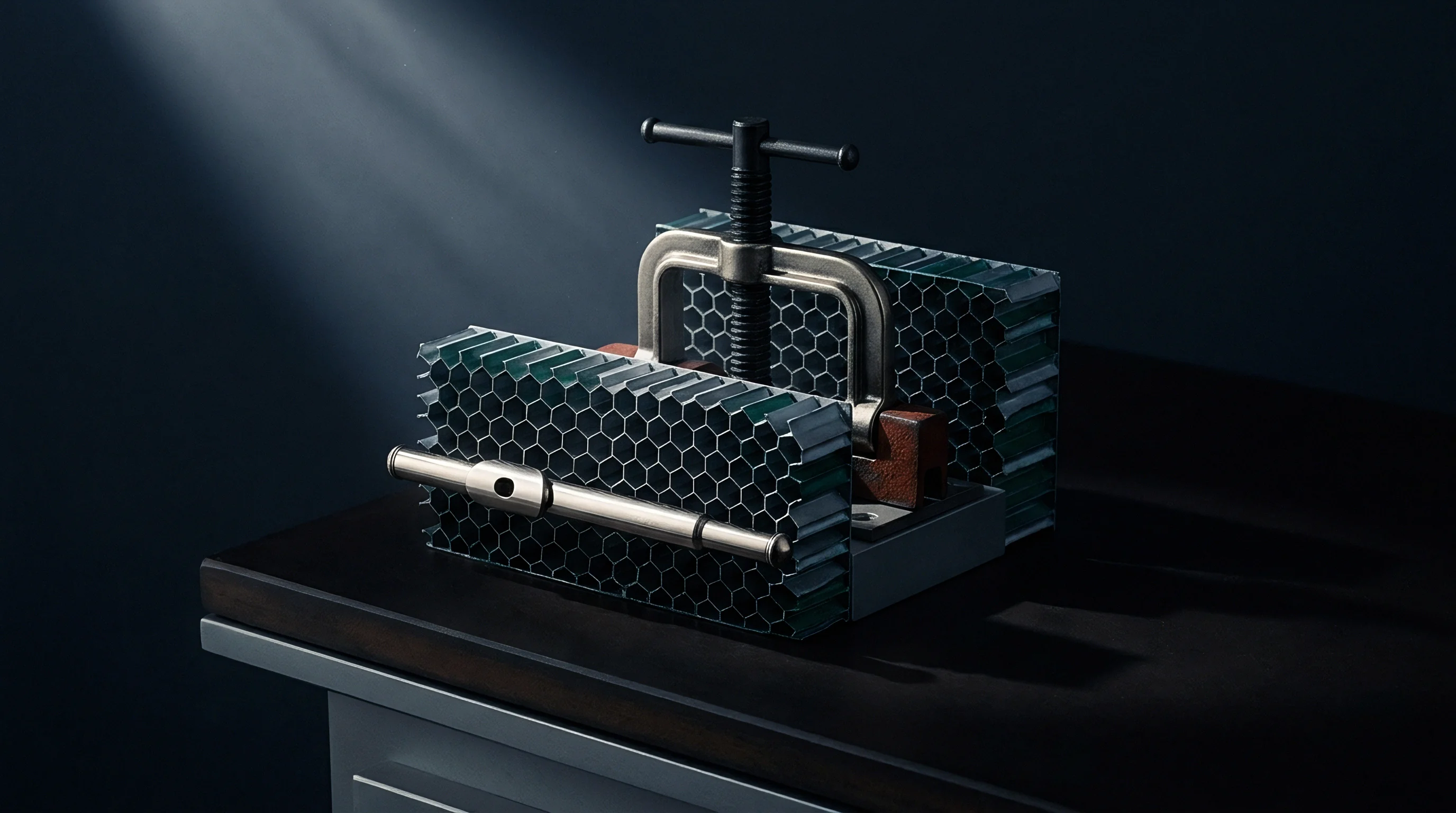
Deformation Zones in Rotary Creasing Tools
Penetration of a male scoring wheel into board stock forces inner plies down into female channel cavities. This displacement creates three distinct deformation zones across the score profile: a central compressive crushed core, two shear transition shoulders, and tension-loaded outer liner regions. Paperboard webs exhibit low out-of-plane shear strength relative to in-plane tensile capacity.
Rotary anvils crush liners.
Excessive penetration depth or incorrect male-to-female tool alignment forces internal plies to shear prematurely. When internal plies split into thin, delaminated sub-layers without rupturing the exterior liner, the crease retains a clean surface appearance. Fluting wall resistance collapses.
Internal voiding severely compromises the structural stiffness of the score line under vertical compressive loads.

Microstructural Damage Modes in Fiber Webs
Compressive crushing on the score interior induces shear stresses that rupture hydrogen bonding between adjacent cellulose strands. The degree of microstructural destruction depends on sheet moisture content, fiber orientation relative to the score axis, and raw material pulp composition. Recycled paper fibers exhibit lower elongation to break than virgin kraft fibers, increasing susceptibility to micro-fracture during creasing.
ISO 3037 edge compression testing mandates uncreased test specimens, concealing the 15 to 30 percent load capacity drop caused by rotary scoring wheels.
Acoustic attenuation measurements capture cumulative microstructural failure modes across the entire crease width:
- Liner micro-cracking occurs on outer tension surfaces when local tensile strain exceeds the rupture limit of refined virgin pulp fibers.
- Internal delamination splitting forms parallel planar voids within inner liner plies, scattering high-frequency sound pulses across the thickness.
- Fluting collapse propagation flattens corrugated arch structures adjacent to the score shoulder, reducing localized out-of-plane bending resistance.
- Tensile fiber pullout separates bonded cellulose strands along the crease axis, diminishing stress transfer capacity across folded panel corners.
Whether localized micro-fractures in recycled medium fluting recover elastic stiffness under dynamic ambient humidity cycles remains an open question in corrugated paper science.

Bending
Mechanical hinges created along converting scoring lines govern how finished carton flaps collapse during automated box assembly. A score line must exhibit sufficiently low bending stiffness to fold cleanly at ninety degrees without causing panel distortion. Excessive reduction in score stiffness destabilizes the vertical corners of assembled corrugated containers, where structural load capacity concentrates.
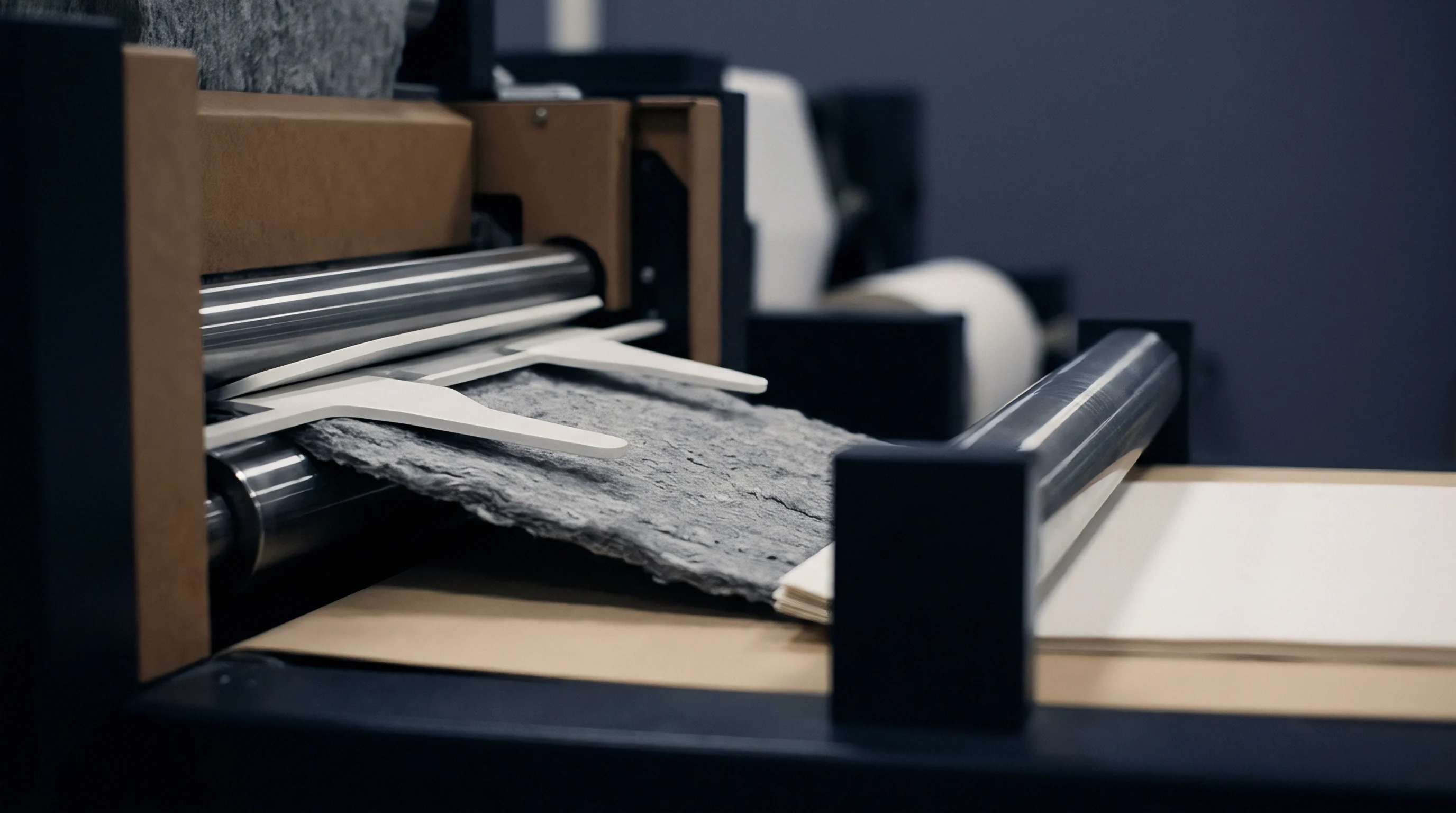
Moment-Rotation Relationships in Folded Panels
Standard laboratory score quality testers measure the peak force needed to swing a creased board specimen through ninety degrees. The resulting moment-rotation curve reveals initial score resistance, yield point behavior, and residual folding torque. An ideal crease demonstrates a steep initial reduction in bending moment followed by a stable, low resistance plateau during full ninety-degree folding.
When scoring wheels crush board stock too aggressively, the score line loses structural integrity. Caliper loss reduces capacity. The crease folds easily during converting, but residual load-bearing capacity drops precipitously.
Ultrasonic wave amplitude tracking directly mirrors the decline in residual bending stiffness recorded on laboratory score testing instruments.
How Does Attenuation Map to Residual Bending Stiffness?
Empirical testing demonstrates a strong non-linear drop in structural resistance as acoustic transmission across the score diminishes. High attenuation values signal severe internal matrix breakdown, reducing the score line effective bending stiffness (Sb).
| Board Combination (gsm) | Score Attenuation (dB) | Crease Bending Moment (N mm) | Edge Compression Loss (%) | Box Alignment Error (deg) |
|---|---|---|---|---|
| 150 Kraft / 110 Fluting / 150 Kraft | 3.5 | 142 | 4.2 | 0.3 |
| 175 Kraft / 120 Fluting / 175 Kraft | 7.2 | 118 | 11.5 | 0.8 |
| 200 Recycled / 127 Fluting / 200 Recycled | 12.8 | 84 | 22.4 | 1.6 |
| 300 Kraft / 150 Fluting / 300 Kraft | 19.4 | 52 | 36.8 | 2.9 |
Linear models fail here. A balance needs to exist between low folding resistance during box setup and high edge stiffness under vertical loading. Crease depth dictates failure.
Attenuation readings between 4 dB and 8 dB generally indicate optimal score formulation, balancing low folding torque against structural wall stability.
Deep score penetration reduces folding resistance while sacrificing edge load capacity.
Load
Container top-to-bottom compression resistance relies on vertical panel wall integrity and score line edge support. Box compression test performance correlates directly with the edge compression test value of combined board and total panel perimeter dimensions. Conventional predictive equations treat vertical score lines as rigid geometric boundaries.
Production creasing reduces edge strength along vertical corner scores, degrading actual stacking performance below theoretical model calculations.

McKee Model Extensions for Creased Corner Load Bearing
Traditional formulations calculate ultimate compression capacity using uncreased edge compression strength, caliper, and box perimeter dimensions. The standard McKee relationship assumes uniform structural resistance across the entire container wall perimeter:
BCT = k · ECTa · (U · d)b
Where BCT represents maximum box compression force, ECT is uncreased edge compression strength, U is box perimeter, d is combined board caliper, k is an empirical constant, and a and b are exponential parameters typically set to 0.75 and 0.25.
To account for localized score degradation, a crease attenuation retention factor (Sr) adjusts the theoretical value:
BCTretention = Sr · BCT
Sr = 1.0 – γ · (αdB – α0)η
The term αdB denotes measured inline ultrasonic attenuation, α0 represents baseline board attenuation before scoring, while γ and η are material coefficients derived from liner pulp elasticity and fluting geometry. Panel edges carry weight. Stacking failure occurs when vertical corner scores buckle under sustained top load weight.
Score attenuation values rising above baseline signal levels indicate excessive anvil penetration long before liner cracking becomes visible to line operators.

Empirical Correlation Curves for Compression Retention
Regression data gathered across multiple linerboard grammages maps decibel attenuation directly against percentage compression loss. As ultrasonic attenuation increases from 2 dB to 20 dB, box compression retention declines from 98 percent to less than 65 percent of theoretical capacity. Over-creasing destroys box capacity.
Multiple structural mechanisms drive compression loss along creased box corners:
- Corner load transfer asymmetry shifts vertical stresses away from damaged crease hinges onto uncreased panel centers, accelerating wall buckling.
- Crease bulge buckling initiation creates local out-of-plane eccentricities that trigger premature panel collapse under static stacking weight.
- Moisture-induced score softening accelerates creep deformation along delaminated fiber matrices during high-humidity cold-chain storage.
- Crease shear slip under top-load stress allows adjacent liner plies to slide past each other along micro-fractured score boundaries.
Standard purchase contracts referencing TAPPI T 811 allow suppliers to test uncreased board strips, shifting the financial risk of score line compression loss entirely onto the box buyer.


Gauge
Non-destructive testing hardware installed on high-speed folder-gluer or rotary die-cutter equipment captures real-time sheet metrics. In-line ultrasonic measuring heads consist of non-contact air-coupled transducers positioned directly above and below score line paths. These transceivers continuously evaluate score attenuation without slowing down web transportation speeds or causing surface scuffing.

Air-Coupled Transducer Configurations for Line Speeds
Piezoelectric elements mounted within focused acoustic housings eliminate physical contact with moving paperboard webs running up to 400 meters per minute. High-frequency acoustic signals cross small air gaps through focused acoustic impedance matching layers. Signal-to-noise ratios remain high when transducers operate at resonant frequencies between 100 kHz and 300 kHz.
Sensor alignment alters baseline.
Air turbulence around high-speed converting cylinders creates phase noise that focused bandpass filters suppress during acoustic signal processing.
Phase-locked loop circuits filter environmental motor hum and aerodynamic turbulence around fast-moving rotary cylinders. Transducers capture acoustic loss.
| Sensor Configuration | Operating Speed (m/min) | Signal SNR (dB) | Frequency Range (kHz) | Measurement Repeatability (%) |
|---|---|---|---|---|
| Wheel-Coupled Contact Transducer | 150 | 38.5 | 50 to 200 | 98.2 |
| Air-Coupled Non-Contact Array | 400 | 29.1 | 100 to 500 | 96.8 |
| Laser-Ultrasonic Hybrid Sensor | 600 | 24.6 | 200 to 1000 | 93.5 |

Calibration Routine for Rotary Creasing Modules
Standardizing sensor voltage baseline values requires precise air-gap spacing and clean board references before starting production.
- Set the air-gap distance between transmitting and receiving transducers to exactly 15 millimeters using a micro-adjustment gauge.
- Pass an unscored sample of target substrate through the measuring head at production line velocity to capture baseline signal amplitude.
- Adjust amplifier gain settings until the root-mean-square voltage output reaches 5.0 volts peak-to-peak.
- Perform three test scores at progressive anvil penetration steps of 0.2 millimeter increments.
- Map observed decibel attenuation against off-line crease stiffness measurements to populate the real-time lookup array.
Miscalibrating the baseline attenuation threshold leads converting lines to ship weakened corrugated boxes that crush under standard pallet stacking loads.


Margin
Over-specifying linerboard grammage to compensate for unpredictable converting damage increases raw material expenditure across high-volume packaging runs. Packaging engineers frequently specify heavier paper grades to ensure safety factors when score damage reduces container compression strength. Real-time attenuation monitoring removes process uncertainty, allowing plants to run optimized target board weights without risking field failures.

Paperboard Grammage Reductions via Closed Loop Control
Eliminating localized score damage enables packaging lines to run lighter combined board combinations without sacrificing finished container top-load performance. Anvil penetration governs strength. When closed-loop feedback automatically adjusts scoring rule depth based on inline acoustic attenuation, structural degradation stays within tight control limits.
Moisture weakens creased webs.
A plant running 50 million square meters of corrugated board annually achieves substantial cost savings by reducing combined board basis weight by 10 grams per square meter. Preventing excessive creasing depth preserves intrinsic linerboard compression strength, allowing lower basis weights to achieve identical box compression test ratings.
Financial Payback on Real-Time Scoring Quality Control
Capital expenditure for non-destructive inline acoustic monitoring arrays averages forty to sixty thousand dollars per converting line. Line speed introduces noise. Spoilage reductions during make-ready combined with paper savings generate rapid financial returns on hardware investments.
Consider a representative high-speed folder-gluer installation:
Assume an annual converting line output of 18,000 metric tonnes of C-flute corrugated packaging priced at an average converted material cost of 1,200 dollars per metric tonne. Field claims resulting from crushed corner failure in pallet stacks currently represent 0.6 percent of total shipped volume, generating 129,600 dollars in direct credit notes and freight replacement costs per year. Make-ready waste from manual scoring wheel adjustments accounts for an additional 25 metric tonnes of rejected board per month, costing 360,000 dollars annually in lost material and wasted machine operating time.
Installing an air-coupled four-channel ultrasonic attenuation array reduces scoring make-ready waste by 60 percent, yielding a direct material saving of 216,000 dollars annually. Real-time automatic gap adjustment eliminates over-creasing damage, lowering field compression failure claims by 80 percent and saving 103,680 dollars in annual claims expense. Total annual cost savings equal 319,680 dollars against an initial hardware and integration cost of 52,000 dollars.
Stack strength drops fast. The complete installation achieves full financial payback in less than two and a half months of continuous operation.
Controlling scoring wheel penetration through real-time attenuation monitoring secures consistent container stacking strength while preventing unnecessary raw material over-specification.