Axial Load Precision
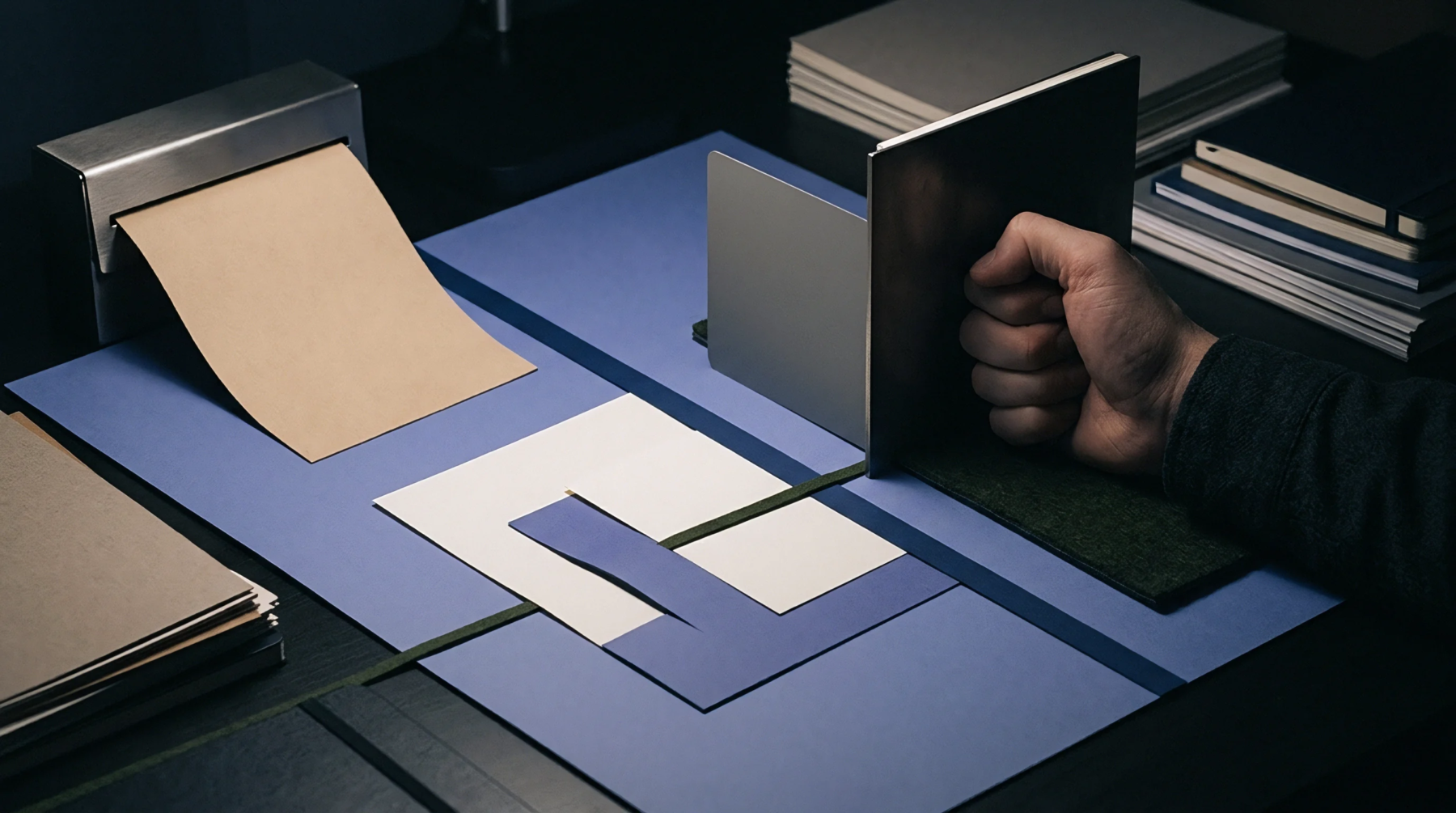
True perpendicular and concentric positioning of the moving load cell carriage relative to the base anvil ensures pure uniaxial stress during tensile and peel testing. In materials testing systems for paper, films, and laminates, crosshead alignment prevents off-axis bending moments that corrupt tensile strength, elongation, and peel resistance measurements. Angular misalignment creates uneven stress distribution across the width of the specimen clamped between the grips.
A misaligned fixture causes premature edge tearing in brittle papers, which yields falsely suppressed tensile energy absorption readings. Universal testing machines must maintain rigorous parallelism throughout the full stroke of the vertical column.
Verification Protocols
Mechanical alignment verification requires precision dial indicators, optical laser sensors, or specialized strain-gauged load verification cells. Misalignment exceeding fractions of a degree introduces severe shear components into pure tensile configurations, invalidating compliance with standard testing methods. In high-resolution testing of thin barrier foils or pressure-sensitive tape delamination, crosshead alignment ensures that recorded peel forces reflect true interfacial adhesion rather than asymmetrical torque on the load frame.
Torsional twist during crosshead translation similarly distorts modulus calculations in low-strain regions.
Operational Boundaries
Grip jaw clamping pressure must be balanced symmetrically across the face to preserve the mechanical alignment established by the machine columns. Uneven pneumatic grip clamping offsets the neutral axis of the test strip, reintroducing parasitic forces even when crosshead alignment satisfies machine tolerance standards. In high-capacity testing frames, heavy fixtures can deflect the guide columns under maximum load, shifting alignment dynamically during the test cycle.
Geometric alignment remains valid only within the elastic deflection limits of the structural testing frame.