Differential Brass Die Thermal Expansion Calibration in Multi Impression Stamping
Precompensate brass stamping dies by scaling CAD repeat centers outward from platen origin using inverse thermal expansion formulas before CNC engraving.

Offset
Dimensional accuracy across wide-platen stamping presses degrades when temperature rises. Tooling drafts demand compensation. When engraving multi-impression brass dies for hot foil stamping or combination embossing, calculating differential thermal expansion between the brass die and the ambient sheet layout separates viable production runs from catastrophic register drift.
Engravers mill brass at ambient room temperature, typically 20 degrees Celsius. In contrast, hot foil stamping operations run between 100 degrees Celsius and 140 degrees Celsius, with combination embossing platens frequently reaching 160 degrees Celsius. Brass possesses a high coefficient of thermal expansion, spanning 18.5 to 20.0 times 10 to the negative sixth power per Kelvin, whereas the carbon steel chases and honeycomb mounting beds expand at roughly 11.0 to 12.5 times 10 to the negative sixth power per Kelvin.
The printed paperboard sheet, meanwhile, undergoes virtually zero thermal expansion, but instead experiences hygrothermal contraction as platen heat drives off bound moisture.
The resulting disparity causes outer die impressions to migrate outward from the press center line. On small formats with two or four cavities, this physical movement stays within commercial register tolerances of plus or minus 0.20 millimeters. On a 1020-millimeter or 1060-millimeter sheet running a 40-up carton layout, the outer cavities wander by more than a full millimeter if cut to ambient CAD dimensions.
Register marks expose drift. That magnitude completely destroys perimeter foil-to-print alignment, blinding embossed borders and cutting off foil elements along carton score lines.
At an operating temperature of 130 degrees Celsius, an uncompensated brass die set spanning 920 millimeters expands by 1.98 millimeters relative to ambient room dimensions.
Linear Expansion Mechanics across Formats
Substrate stability remains relatively fixed while metal tooling grows under thermal excitation. Solid bleached sulphate board exhibits an equilibrium moisture content between 6.0 and 7.5 percent under standard pressroom conditioning per ISO 187 at 23 degrees Celsius and 50 percent relative humidity. Passing through a 120-degree stamping zone during a 180-millisecond dwell strips up to 0.4 percent of that moisture in the contact zone, producing a sheet contraction of 0.05 to 0.12 percent across the grain direction.
Linear expansion of the die works in the direct opposite direction.
Thermal expansion of brass follows a predictable linear relationship across stamping temperature bands. Machining brass alloy CW614N, commonly designated C36000 free-cutting brass, features a certified coefficient of thermal expansion of 19.3 times 10 to the negative sixth power per Kelvin between 20 degrees Celsius and 100 degrees Celsius, rising to 20.1 times 10 to the negative sixth power per Kelvin when evaluated across the 20 to 200 degree range. Structural steel platen material exhibits an expansion rate of 11.5 times 10 to the negative sixth power per Kelvin over the same operational span.
Toolmakers calculate the linear dimensional growth using the formula where change in length equals original length multiplied by the material thermal coefficient multiplied by the temperature differential.
| Tooling Material | Coefficient (10⁻⁶/K) | Bed Width (mm) | Base Temp (°C) | Run Temp (°C) | Calculated Shift (mm) |
|---|---|---|---|---|---|
| Free-Cutting Brass C36000 | 19.8 | 600 | 20 | 110 | +1.07 |
| Free-Cutting Brass C36000 | 20.1 | 1020 | 20 | 130 | +2.25 |
| Free-Cutting Brass C36000 | 20.4 | 1420 | 20 | 140 | +3.48 |
| Platen Tool Steel 1.2312 | 11.8 | 1020 | 20 | 130 | +1.32 |
| Aeronautical Aluminum 6082 | 23.4 | 1020 | 20 | 130 | +2.63 |
| Magnesium Photoengraving | 26.0 | 1020 | 20 | 130 | +2.92 |
A 1020-millimeter monoblock brass plate heated to 130 degrees Celsius expands by 2.25 millimeters across its outer boundary. The underlying steel chase expands by only 1.32 millimeters under identical thermal saturation. That generates a 0.93-millimeter mechanical mismatch between the brass mounting anchor points and the steel platen tapped grid.
If the die is fastened rigidly across its perimeter, internal compressive stresses build rapidly, leading to mechanical plate bowing, uneven impression depth, and localized foil burnishing. Edge units fail first.
Precompensation Arithmetic for Machine Centers
Calculations for step-and-repeat layouts factor both tool material properties and anticipated platen temperatures. The calculation governs placement. Rather than cutting the die to match the cold print layout, the toolmaker applies a negative scaling factor to the CAD file during CNC toolpath generation.
The compensation factor equals the inverse of one plus the product of the coefficient of thermal expansion and the temperature differential. The mathematical equation expresses this scaling ratio as one divided by open parenthesis one plus alpha multiplied by delta tee close parenthesis.
Take an operational scenario involving a 40-up pharmaceutical carton layout. The job runs on an 820-millimeter brass die layout width on a BMA format platen press. Ambient shop temperature sits at 21 degrees Celsius, with target hot foil stamping temperature set at 126 degrees Celsius, producing a delta tee of 105 Kelvin.
Using an operational brass coefficient of 19.6 times 10 to the negative sixth power per Kelvin, the calculated expansion multiplier equals 0.002058. Inverting this factor dictates a shrinkage scale factor of 0.997946 applied to the CAD file before generating engraving passes.
- Centerline Origin Definition fixes the absolute Cartesian zero coordinate at the exact geometric midpoint of the master layout sheet.
- Axis Scaling Application imposes the thermal compensation percentage outward from the designated origin point across both horizontal and vertical vectors.
- Cavity Vector Preservation maintains the internal geometric scale of small intricate brand elements while compressing the interstitial distances separating repeating cavities.
- Verification Measurement documents cold inspection distances across outer register crosses on a coordinate measuring machine before dispatching the plate to the press floor.
Tolerances compound across width. When executing step-and-repeat compensation, the engraver keeps individual emblem features true to size while compressing the center-to-center distances separating distinct carton positions. Compressing an intricate logo script by 0.2 percent causes unnoticeable change on an eight-millimeter mark, yet compressing the repeat pitch across twenty rows pulls the outermost impressions back into perfect alignment once the die blooms to full operating temperature.
Neglecting calculated expansion during tool engraving transforms wide-format jobs into systematic scrap, forcing expensive tool re-cuts and unrecoverable press downtime.


Heat
Energy delivery across heavy stamping platens rarely distributes evenly. Thermal gradients shift local centers. Stamping presses utilize resistance heating cartridges embedded in zone plates behind the chase.
Center zones trap thermal energy because they radiate only toward the front face through the die, whereas outer perimeter zones lose heat constantly to the surrounding ambient air, machine side frames, and heavy casting bulkheads. Thermal imaging of a seasoned 1060-millimeter platen regularly reveals core temperatures running at 135 degrees Celsius while the perimeter corners struggle to maintain 121 degrees Celsius.
This differential thermal profile creates non-linear physical distortion across the tooling face. A brass plate mounted over such a platen does not expand as a uniform, planar rectangle. It forms a subtle barrel-shaped contour, where the center expands aggressively along both lateral and longitudinal axes, and the corners lag behind.
The perimeter loses heat. Precompensated step-and-repeat calculations that assume a flat 130-degree profile across every square centimeter will consequently over-compensate the cold corners and under-compensate the hot core.
Thermal displacement accumulates from the geometric center outward toward the grippers and side guides.
Where Do Thermal Gradients Compromise Outer Cavities?
Center cavities experience continuous contact with dense heating grids, whereas edge zones radiate thermal energy into open press frames. The temperature delta across a typical cross-section ranges from 8 to 15 degrees Celsius depending on chase insulation condition and machine hood extraction volume. Because the expansion calculation depends directly on the local temperature differential, each row and column of a multi-impression layout experiences a slightly varied expansion coefficient in practice.
Precision tooling demands stable stock.
Cold chases distort dies. The converting field maintains two conflicting viewpoints regarding how to manage this localized distortion. Die makers argue that modern digital multi-zone platens compensate for edge losses by driving corner cartridges at higher duty cycles.
Pressroom supervisors observe that thermal conduction through heavy brass distributes heat laterally anyway, smoothing out zone differentials into an unpredictable parabolic curve that defies purely zoned electronic correction.
| Platen Zone | Nominal Setpoint (°C) | Actual Measured (°C) | Localized ΔT (K) | Outer Displacement (mm) | True Register Offset (mm) |
|---|---|---|---|---|---|
| Center Core (Zones 4-5) | 130 | 134.5 | +114.5 | 0.00 | -0.02 |
| Intermediate Band (Zones 2, 7) | 130 | 129.0 | +109.0 | ±0.48 | +0.04 |
| Operator Edge (Zone 1) | 130 | 123.2 | +103.2 | ±0.89 | +0.16 |
| Drive Side Edge (Zone 8) | 130 | 122.8 | +102.8 | ±0.91 | +0.18 |
| Lead Gripper Bar (Zone 3) | 130 | 125.1 | +105.1 | ±0.62 | +0.11 |
| Trailing Platen Edge (Zone 6) | 130 | 124.0 | +104.0 | ±0.68 | +0.13 |
| Data gathered across four-hour stabilization cycle on 1.2312 steel chase using calibrated surface contact thermocouples. | |||||

Heating Zone Stabilization and Dwell Control
Multi-zone digital controllers regulate electrical resistance cartridges across the upper press bed. Zone controllers cycle heaters independently. Standard platens divide the working bed into six, eight, or twelve individually monitored thermal zones, each governed by its own embedded thermocouple.
When the press idles, heat accumulates throughout the tooling block, driving the entire mass toward equilibrium. The moment running commences, cold paperboard sheets strip thermal energy from the die face with every stroke.
Running speeds of 5,000 sheets per hour present a steady thermal sink. At this cadence, incoming 20-degree paperboard absorbs thermal energy from the die surface faster than internal conduction can supply it from the heating plate. The face temperature drops by 6 to 12 degrees Celsius within the first two hundred impressions before cartridge controllers ramp up amperage to re-establish setpoint equilibrium.
If an operator begins registering foil passes during this dynamic recovery curve, registration will walk across the sheet as the dies expand back toward their dynamic equilibrium length.
- Platen Heat-Up Soak Cycle mandates holding the closed, idle press at target operating temperature for a minimum of forty-five minutes before touching fine register adjustments.
- Zone Offset Balancing increases perimeter zone temperature settings by four to six degrees Celsius above center zones to counteract radiative heat sinking into side frames.
- Infrared Face Calibration verifies actual brass surface temperatures against internal platen thermocouple readouts using a calibrated non-contact pyrometer.
- Dynamic Balance Run In processes fifty sacrificial makeready sheets through the active stamping nip to bring die faces into dynamic thermal equilibrium before final visual approval.
Similar physical considerations govern astronomical telescope mirror cells, where dissimilar metals must accommodate thermal drift without pinching optical glass out of its parabolic figure. Stamping presses face the identical mechanical dilemma with sheet register. Die suppliers routinely argue that pressroom ambient humidity and erratic platen heaters invalidate their engraving tolerances.


Chase
Mounting plates and structural carriers determine how expansion translates into cavity displacement. Steel resists thermal movement. The pressman mounts dies either as a single unified monoblock brass plate or as segmented, individual brass dies positioned across a perforated honeycomb chase using hardened toggle hooks.
The structural choice between these two systems dictates how thermal growth behaves mechanically under pressure.
Monoblock brass plates possess massive internal structural integrity. When a full-sheet brass plate expands, the entire metal field moves outward from its center of resistance. If the plate is bolted down securely at multiple points across a steel chase, the mismatched expansion coefficients between the steel and the brass spark tremendous mechanical shear.
The brass plate will physically shear small mounting bolts or buckle vertically away from the chase face, forming an uncorrectable hollow that obliterates impression pressure in the center of the sheet.
Individual dies floating on honeycombs track platen movement while unified monoblock plates force internal shear against the sheet.
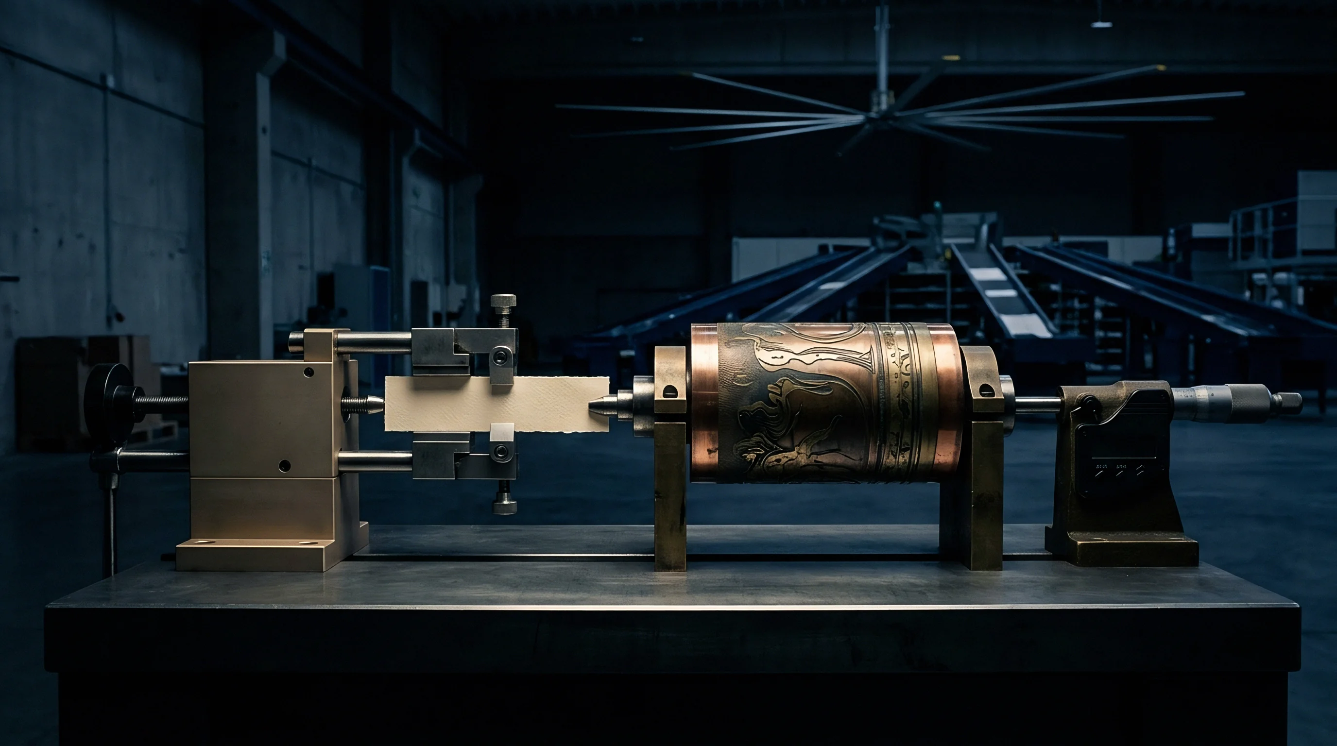
Monoblock Tooling versus Segmented Placement
Machining multiple carton positions from a single continuous brass slab preserves cavity-to-cavity spacing relative to the metal itself. Segmented placement, on the other hand, breaks the layout into individual dies, one per carton position. Individual dies eliminate cumulative thermal expansion across the total sheet width.
An individual 80-millimeter by 120-millimeter brass die running at 130 degrees Celsius expands by only 0.17 millimeters across its major dimension, an amount easily absorbed within print tolerances.
However, segmented individual dies present a different mechanical trap. Each die sits atop a toggle hook clamped into a steel honeycomb chase. As the steel chase heats up, the holes in the honeycomb expand according to the thermal coefficient of steel, not brass.
The center-to-center distance between individual dies therefore tracks the expansion of the steel honeycomb bed, not the brass tooling. Precompensation for individual dies mounted on a honeycomb must therefore scale the die positions according to the steel chase expansion rate, while leaving the internal engraving details scaled to the brass coefficient.
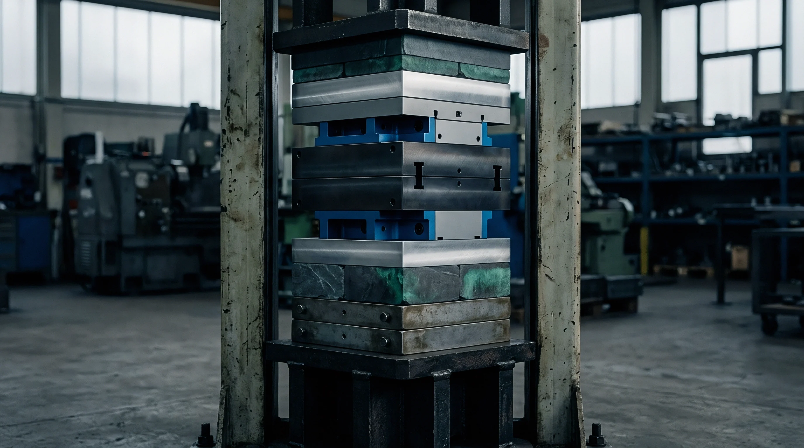
Toggle Restraint Mechanics on Honeycomb Beds
Hardened steel hooks lock die edges against perforated platen holes under substantial clamping force. Loose toggles invite registration crawl. The standard toggle hook engages the beveled 30-degree edge of a brass die, applying both downward clamping force and lateral positioning restraint.
As the press cycles, cyclic impression tonnages ranging from 150 to 300 tons drive the die face into the counter plate, creating tremendous frictional grip that resists lateral sliding during the split second of impression.
Between impressions, when the platen opens, the die is relieved of vertical load. The internal thermal expansion stress attempts to relieve itself by pushing outward against the toggle jaws. Standard bevel-lip toggles allow microscopic outward slippage if torqued unevenly.
Uneven toggle torque across a forty-cavity chase causes individual dies to walk randomly across the honeycomb face during extended production runs.
- Toggle Crest Fracture results when excessive clamping torque over-stresses the thin bevel shelf of the brass die, leading to edge chipping and sudden loss of positioning tension.
- Thermal Ratcheting occurs as the die slips outward during platen open dwell but fails to return upon cooling, progressively walking outer cavities further out of register across multiple shifts.
- Chase Web Distortion develops when thermal expansion of tightly butted adjacent dies exerts excessive lateral force against the thin steel webs separating honeycomb holes.
- Heel Lift Separation happens when asymmetrical toggle clamping forces the rear edge of a heated die upward, causing premature foil strike and ghosting halos.
Setup crews avoid locking every toggle with equal rigidity. Experienced make-ready technicians designate one master registration point per die, clamping that edge firmly while leaving opposing toggles tightened to a sliding slip-fit specification. Locking the central die firmly while allowing peripheral fasteners to slide preserves overall pattern alignment as metal flows outward.
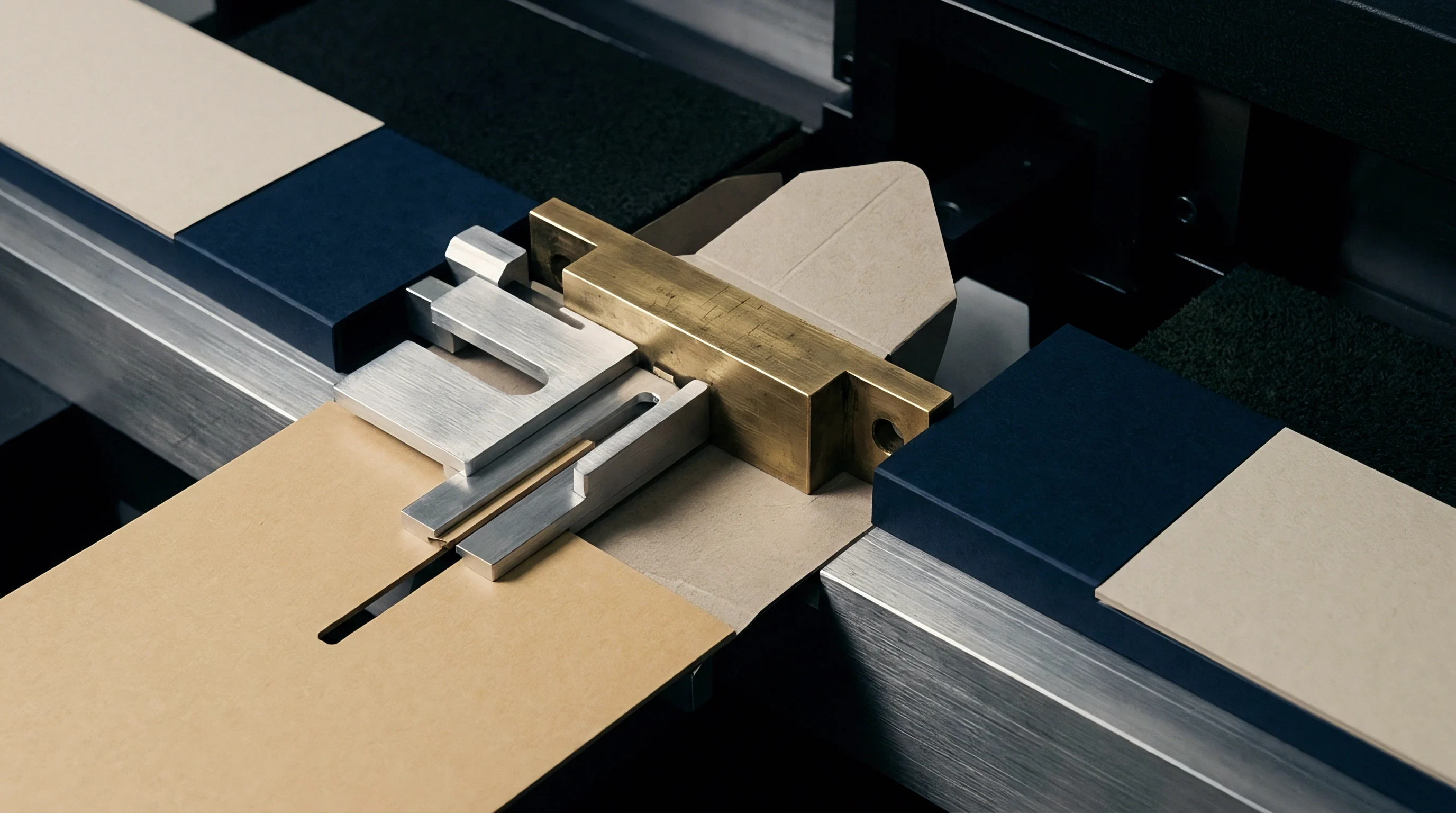

Spoilage
Scrap accumulation accelerates when outer impressions drift outside visual registration tolerances. Sheet stretch compounds errors. Setup waste spikes quickly.
On high-speed automatic platen presses running cosmetic packaging or spirits cartons, foil-to-print misalignment exceeding 0.15 millimeters demands immediate rejection under ISO 12647-2 visual quality metrics. When a multi-cavity layout suffers from differential thermal drift, center cartons look flawless while perimeter cartons reveal exposed print edges, clipped foil vignettes, and skewed hot foil textures.
Press operators facing edge misregistration frequently make the error of moving the entire press register. Moving the side lay or gripper margin to bring the right-hand outer carton into register moves the left-hand outer carton twice as far into scrap territory. The operator begins chasing register across the sheet, burning make-ready stock, running down expensive rolls of metallic stamping foil, and degrading shift throughput.
| Tooling Architecture | Calibration Status | Make-Ready Waste (Sheets) | Running Spoilage (%) | Total Waste Cost (USD) | Shift Downtime (Hours) |
|---|---|---|---|---|---|
| Monoblock Brass 1020 mm | Uncompensated | 1,850 | 6.8% | $8,420 | 3.5 |
| Monoblock Brass 1020 mm | Calculated Precompensation | 450 | 1.1% | $1,780 | 0.8 |
| Segmented Brass on Honeycomb | Uncompensated | 1,200 | 3.9% | $5,150 | 2.4 |
| Segmented Brass on Honeycomb | Steel-Chase Scaled Pitch | 380 | 0.8% | $1,320 | 0.5 |
| Full Steel Micro-Etched Plate | Native Layout Match | 290 | 0.4% | $860 | 0.3 |
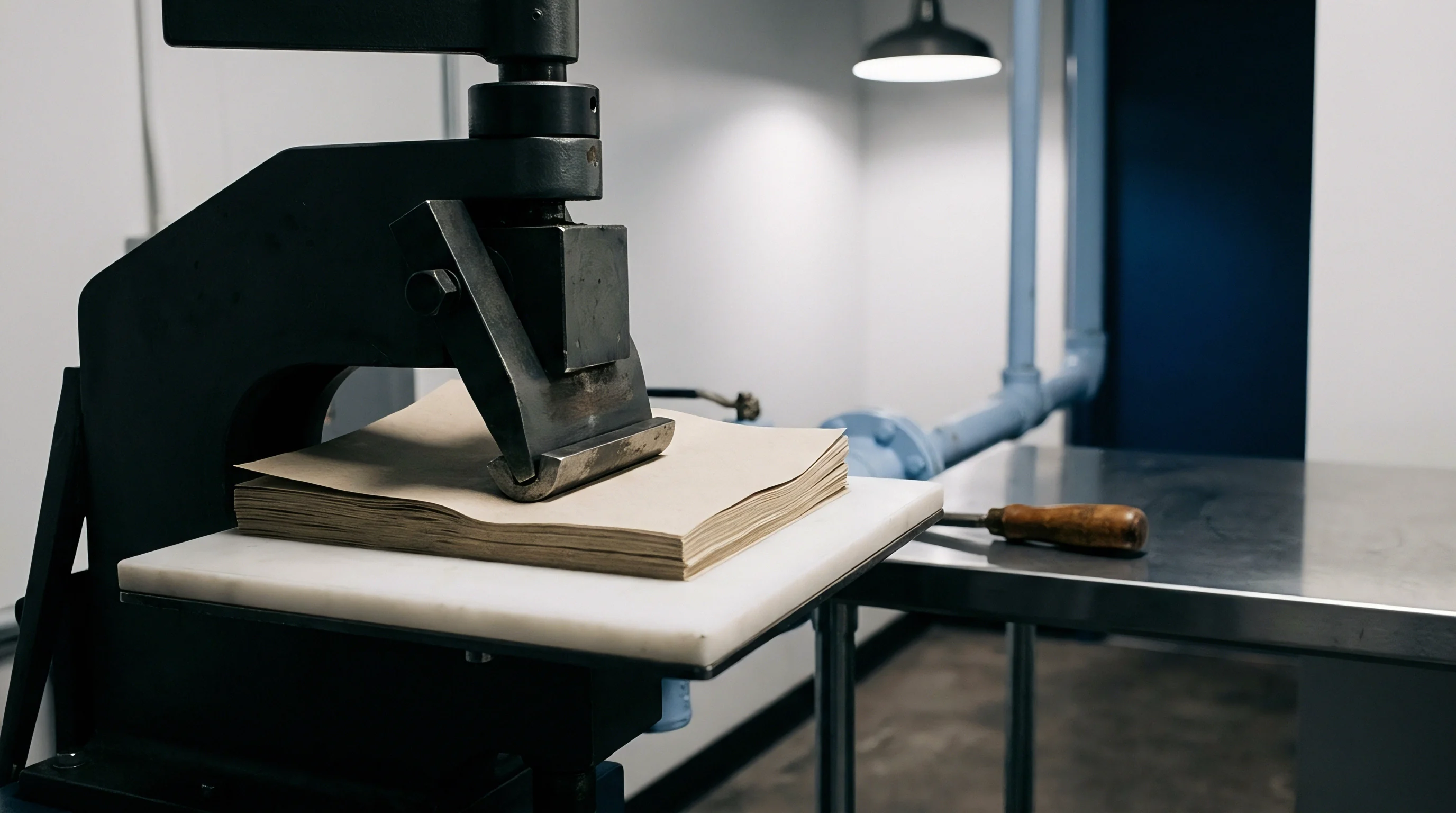
Outer Cavity Misalignment and Image Chasing
Press operators facing edge misregistration frequently make the error of moving the entire press register. The problem lies within the tooling layout geometry, not sheet feed timing or gripper squareness. An operator running thirty-six impressions on an uncompensated brass die set will pull a sheet after five hundred impressions, notice the drive-side perimeter cartons showing foil shifted 0.6 millimeters to the right, and tap the front lay or side register to compensate.
The adjustment immediately throws the operator-side cavities into complete defect status. Modern folding carton finishing operations running luxury packaging cannot afford to sort scrap offline sheet by sheet. If six cartons on a thirty-six-cavity sheet display unacceptable foil drift, the die cutter strips out those defective blanks during automated blanking, reducing the net yield of the entire run by 16.7 percent.
The economic consequence destroys job profitability long before the press reaches sheet twelve thousand.

Make Ready Stabilization Cycles
Running production sheets before the platen reaches thermal saturation wastes costly foil and board. Converting supervisors establish rigid operational disciplines governing machine start-up sequences. Thermal equilibrium requires steady-state operating parameters that include electrical cartridge duty cycles, press speed, and mechanical air circulation around the platen bed.
A press stopped for thirty minutes during lunch cools down sufficiently to shrink brass dies by up to 0.4 millimeters across outer format spans.
Restarting production immediately after an extended idle period generates guaranteed waste for the first three hundred sheets as the tooling warms back to dynamic equilibrium. Astute plants maintain continuous heating regimes, utilizing slow idle cycling or sacrificial running routines to maintain core platen stability. What remains unresolved is whether press manufacturers will ever integrate active dynamic compensation into platen guide rails to counteract thermal shifts mechanically during the run.
Margin
Commercial profitability in stamped folding cartons hinges on balancing tooling expense against running scrap. Monoblock brass tooling for a 1060-millimeter format costs between 4,500 and 8,000 dollars depending on engraving complexity and emboss sculpting depth. Segmented brass dies for a 48-up layout on a honeycomb bed incur initial tooling costs closer to 6,500 dollars, but demand substantially more make-ready labor during setup.
Deciding which architecture to specify requires matching run volumes and reprint frequencies against known thermal performance envelopes.
Tooling budgets frequently tempt buyers into approving uncompensated tooling from lower-cost engravers who lack five-axis coordinate checking or sophisticated thermal scaling software. A two-thousand-dollar savings on initial die purchase disappears completely during the first three hours of make-ready waste on a carton run of fifty thousand units. The finished carton unit cost must carry the burden of added setup waste, slow running speeds caused by manual register corrections, and offline quality sorting fees.
Incorporating DIN 16742 tolerance boundaries into the tooling agreement binds the die engraver to ambient calibration benchmarks rather than unverified hot-state assumptions.
Commercial Tolerances in Multi Impression Formats
Specification sheets for brand packaging frequently dictate foil-to-print registration limits within a strict range of plus or minus 0.20 millimeters. Print margins on folding carton dies often allocate no more than 0.30 millimeters of bleed or trap between printed offset ink edges and stamped metallic borders. When thermal expansion absorbs 0.25 millimeters of that available margin on outer cartons, the converter operates with virtually zero safety latitude for normal sheet wander, gripper tension variation, or board hygroexpansion.
Sourcing managers writing RFQs for multi-impression foil packaging specify dimensional verification protocols in advance. Tooling quotes must state the applied shrinkage compensation ratio, the reference operating temperature assumed by the CAD engineer, and the mechanical reference center used for scaling vectors. Relying on vague verbal assurances that dies are heat ready invites finger-pointing when sheets pull out of register on press.
Purchase Agreement Clauses for Compensated Tooling
Drafting unambiguous tooling orders prevents disputes regarding who bears the cost when dies run off-register. Contract specifications explicitly define whether the engraver assumes a monoblock chase mounting or individual honeycomb toggle placement, because the required compensation scale factors differ by nearly 40 percent between the two setups. If a buyer supplies artwork step-and-repeat files without clearly instructing the engraver to scale cavity positions for thermal growth, the legal liability for resulting scrap rests entirely with the buyer.
When converters subcontract brass engraving, commercial purchase orders include defined validation criteria. Coordinate measuring machine inspection sheets delivered alongside the finished tooling prove that cold dimensions match the precompensated layout. A contractual clause specifying that brass engraving dimensions apply strictly at 20 degrees Celsius under DIN 16742 shift-class tolerances transfers financial liability for thermal misregistration directly back to the engraver unless documented precompensation is delivered.