Mechanical Stress Distribution in Film Laminated Creasing Matrixes
Matching creasing matrix channel width to composite substrate caliper mitigates interlaminar shear stress and prevents film delamination during box folding.

Channel
Steel rule entry into a laminated cartonboard blank forces the composite sheet through localized tensile and compressive strain fields within milliseconds. In film laminated packaging substrates, this mechanical displacement differs fundamentally from unprinted board creasing due to the structural mismatch between the extensible polymeric film and the semi-rigid paperboard core. When the male creasing rule forces the laminated composite down into the counterdie recess, the outer surface film undergoes severe elongation while the interior cellulose fibers compress.
Proper dimensions of the guiding seat determine whether the surface film yields plastically or fractures during subsequent folder-gluer conversion.
Matrix Crease Groove Mechanics
Female scoring grooves establish the spatial boundaries where cellulose fibers deform into a defined ridge during die impression. The mechanical interaction involves three discrete steps: initial contact of the steel rule apex, shear-induced drawdown into the channel recess, and final impression dwell at bottom dead center. During drawdown, the film laminated layer experiences combined bending and tension along the channel shoulders.
Matrix channel width governs the magnitude of peak tensile strain imposed on the outer plastic layer.
Sheet velocity alters strain rate. Polymer film thickness alters bending radius. When the channel is sized too narrow, the male rule pins the laminated sheet against the matrix walls before the board core can fracture internally along its z-direction ply boundaries.
This pinning action generates excessive shear stresses across the film-to-board bond line, initiating micro-delamination before the sheet even exits the die-cutting platen.
Tensile strain within 15-micrometer biaxially oriented polypropylene film reaches 8.5 percent during female channel seat penetration at 23 degrees Celsius and 50 percent relative humidity.
Strain Distribution across Film-Board Composite Structure
Plastically deforming a multi-layer board structure generates steep stress gradients across the boundary between synthetic film coatings and underlying paperboard. Solid bleached board (SBB) and folding boxboard (FBB) absorb compression differently under the rule impact. Folding boxboard relies on internal ply separation within its middle mechanical pulp layers to relieve bending strain.
When a 12-to-15 micrometer film of biaxially oriented polypropylene (BOPP) or polyethylene terephthalate (PET) sits on the top liner, it acts as a continuous tensile membrane. This membrane restricts the natural expansion of the top linerboard fibers, forcing the strain concentration downward into the primary adhesive interface.
Polyethylene channels yield under load. If the matrix channel shoulder lacks sufficient rigidity, the channel wall deflects laterally during impact, broadening the effective channel width and reducing the sharpness of the resulting crease bead. The mechanical relationship governing optimal channel width for film-laminated substrates follows the empirical formulation:
W = 1.5 × t_board + t_rule + 2 × t_film
where W represents the inner matrix channel width, t_board represents the unlaminated board caliper, t_rule is the physical thickness of the steel creasing rule, and t_film accounts for the combined thickness of the film laminate and its dried adhesive layer. Sizing matrixes below this calculated threshold causes immediate surface film cracking along the outer crease apex during 90-degree and 180-degree carton folding.
Selecting a matrix channel width matched to total composite thickness prevents premature delamination of flexible lamination layers.

Shear
Interlaminar stresses along the film-to-board bond line dictate whether the polymeric film stretches plastically or detaches from the underlying cellulose fibers. During matrix penetration, the top surface of the board experiences maximum outward tensile elongation while the bottom surface inside the crease recess undergoes severe mechanical compression. The thin layer of laminating adhesive, typically applied at 1.5 to 3.0 grams per square meter dry coat weight, acts as the primary medium for shear transfer between the stiff cellulose network and the extensible polymer skin.
Adhesive Layer Stress Transmission
Polyurethane and acrylic bonding formulations transfer mechanical loads from the outer protective film into the top linerboard fibers. When the creasing rule forces the laminate into the matrix channel, the velocity of deformation creates dynamic shear rates exceeding 1,000 reciprocal seconds within the thin adhesive film. If the adhesive possesses high shear modulus but low elongation at break, it transfers excessive force directly to the uppermost cellulose fibers, causing fiber tear directly beneath the film surface.
Moisture loss reduces board strain capability. Adhesive weight governs peel strength. Conversely, a highly compliant adhesive deforms elastomericly under load, allowing the lamination film to slide locally over the paperboard base.
While this sliding reduces tensile stress spikes within the film, it creates unattached film blisters along the crease shoulders. These blisters flatten visually under platen pressure but pop open when the die-cut blank passes through high-speed folder-gluer belt transfers.

Polymer Film Orientation and Yield Behavior
Extrusion orientation controls how synthetic films react under transverse tension during high-speed scoring passes. Biaxially oriented polypropylene exhibits balanced tensile strength in machine and cross directions, yet its plastic yield point remains sensitive to localized strain rates. Metallized PET films exhibit significantly higher elastic moduli and lower strain capability than un-metallized BOPP films, making them vulnerable to mechanical necking along matrix edges.
Paperboard fibers collapse under shear. Failure modes observed during high-volume converting runs stem directly from imbalances between substrate stiffness, film yield point, and matrix channel geometry.
- Interlaminar Bond Splitting occurs when peak internal shear stresses exceed the adhesive layer peel strength under rapid rule displacement.
- Surface Film Crazing develops across high-modulus polyester laminates under sharp bending radii inside narrow matrix channels.
- Fibre Ridge Collapse manifests when soft matrix walls allow lateral spreading of the board core under high compressive loads.
Standard ISO 1924-2 tensile evaluation of laminated substrates predicts matrix cracking risks when cross-direction stretch falls below three percent.
| Film Type | Caliper (µm) | Adhesive Base | Substrate | Peak Shear Stress (MPa) | Observed Failure Mode |
|---|---|---|---|---|---|
| BOPP Gloss | 12 | Waterborne Acrylic | 300 µm FBB | 4.2 | Controlled Plastic Yielding |
| BOPP Matt | 15 | Solventless Polyurethane | 350 µm FBB | 5.8 | Interlaminar Adhesive Debonding |
| PET Gloss | 12 | Solventless Polyurethane | 320 µm SBB | 7.1 | Top Liner Fiber Rupture |
| Cellulose Acetate | 14 | Waterborne Acrylic | 380 µm CRB | 3.1 | Transverse Film Micro-Cracking |
Inadequate adhesive film anchorage causes extensive surface peeling across automated folder-gluer lines, rejecting entire packaging lots before shipment.


Anvil
Base support structures beneath the scoring location regulate how force dissipates into the steel die-cutting plate during peak impact. The anvil assembly consists of the cutting plate surface, the pressure-sensitive adhesive backing tape, and the raised shoulders of the matrix strip itself. Each component contributes to the overall vertical spring constant of the creasing counterdie system.
Excessive compliance in the matrix base allows the female channel to sink under platen impression, reducing effective score depth and creating inconsistent crease bead heights across large format dies.
Counterplate Elastic Deformation
Under high platen tonnages, steel base plates and counterdie chamfers flex slightly to absorb transient impact energy. A standard ground steel cutting plate features a surface hardness between 35 and 50 HRC. When press settings apply 300 to 400 metric tonnes of total impression force across a full platen layout, local compressive stresses beneath individual creasing rules exceed 80 megapascals.
Plastic matrix bases made from extruded polyvinyl chloride (PVC) flex elastomericly under these pressure levels, whereas composite pressboard or synthetic fiber-reinforced matrixes retain tight dimensional stability.
Platen pressure forces matrix compaction. Steel counters resist lateral deflection. Scoring width determines bead volume.
The deflection profile across the matrix channel floor directly alters the stress redistribution pattern inside the cellulose matrix. If the base material deforms non-uniformly, the crease bead develops asymmetrical shoulders, forcing the surface film to stretch over an uneven radius during carton erection.
Does Matrix Base Hardness Alter Interface Shear Strain?
Varying the shore hardness of supporting shoulders alters the peak forces concentrated along the score shoulders. Harder matrix shoulders, ranging from 95 to 98 Shore A, force the paperboard substrate to shear cleanly along the inner rule boundary. This sharp shearing action establishes a precise hinge location, reducing the total bending moment needed to fold the board by up to 35 percent.
However, the hard shoulder edge increases localized contact pressures against the protective lamination film.
Counterdie alignment errors split laminates. If the male rule deviates from the exact centerline of a rigid matrix by more than 0.03 millimeters, the severe asymmetrical stress concentration causes immediate film tearing along the tight-side shoulder wall.
- Verify cutting plate cleanliness using solvent wipes to eliminate oil films before matrix installation.
- Position the plastic locator pin securely over the 2-point or 3-point steel rule apex across the entire impression die.
- Transfer the creasing matrix to the ground counterplate under a slow, manual press turn at partial tonnage.
- Peel away the carrier locator strip at a shallow 30-degree angle to avoid distorting the matrix shoulders.
Softer matrix shoulder polymers absorb micro-impact forces and protect delicate metallic foil stampings from edge chipping.
Tooling vendors often claim that matrix shoulder shoulder lifting arises exclusively from dirty platen plates rather than mechanical fatigue of the pressure-sensitive adhesive layer.

Footprint
Spatial stress concentrations beneath the female seat vary non-linearly across the width of the score location during sheet impression. Numerical modeling and physical cross-sectional strain analysis demonstrate that the highest shear strains do not occur at the apex of the male rule, but rather at the rounded entry radii of the female channel shoulders. As the creasing rule pushes the laminated board into the matrix cavity, the composite material wraps tightly around these shoulder radii, subjecting the outer lamination film to extreme localized tensile stress combined with severe bending friction.

Finite Element Strain Field Mapping
Numerical modeling of composite board deflection reveals triaxial stress vectors radiating outward from the rule tip. The principal tensile stress acts parallel to the outer film surface, striving to pull the polymer film apart. Simultaneously, high compressive stress acts perpendicular to the film surface where it contacts the metal rule tip.
This combined stress state drives shear deformation through the thickness of the board substrate.
Polypropylene films stretch before rupture. Matrix wear alters channel geometry. Fillet radii on commercial matrix shoulders typically range from 0.2 to 0.5 millimeters.
Reducing this radius below 0.2 millimeters creates a sharp shearing edge that concentrates mechanical energy into a tight spatial footprint, dramatically raising the probability of surface lamination fracture. Increasing the shoulder radius above 0.5 millimeters spreads the deformation force over a wider area, but produces a wide, ill-defined crease bead that increases folding resistance during high-speed packaging assembly.

Platen Velocity and Dynamic Load Effects
Running speed directly influences the deformation kinetics of synthetic films attached to paperboard surfaces. Die-cutting platens operating at 8,000 sheets per hour subject each score line to impact dwell times under 20 milliseconds. At these strain rates, polymeric films exhibit elevated tensile yield strength and reduced strain-to-failure capacity compared to static bench testing values.
Dynamic forces concentrate at shoulders. Viscoelastic dissipation within both the cellulose fibers and the polymeric lamination layer converts a portion of the mechanical deformation energy into localized heat. On rapid, continuous runs, heat buildup at matrix entry points can soften thermoplastic adhesives, lowering their resistance to interlaminar shear displacement.
| Matrix Base Material | Shoulder Radius (mm) | Press Speed (sheets/hr) | Max Film Tensile Stress (MPa) | Max Board Shear Stress (MPa) | Film Cracking Risk Index |
|---|---|---|---|---|---|
| Standard PVC Pressboard | 0.20 | 4,000 | 48.5 | 12.1 | High |
| Standard PVC Pressboard | 0.35 | 4,000 | 34.2 | 9.4 | Low |
| Fiber Composite Base | 0.35 | 7,500 | 41.8 | 11.0 | Moderate |
| Steel Base Matrix | 0.35 | 9,000 | 45.0 | 11.8 | Moderate |
| Steel Base Matrix | 0.50 | 9,000 | 31.5 | 8.2 | Negligible |
How dynamic viscoelastic relaxation within bio-based lamination adhesives affects high-speed score recovery remains unresolved across converting literature.

Caliper
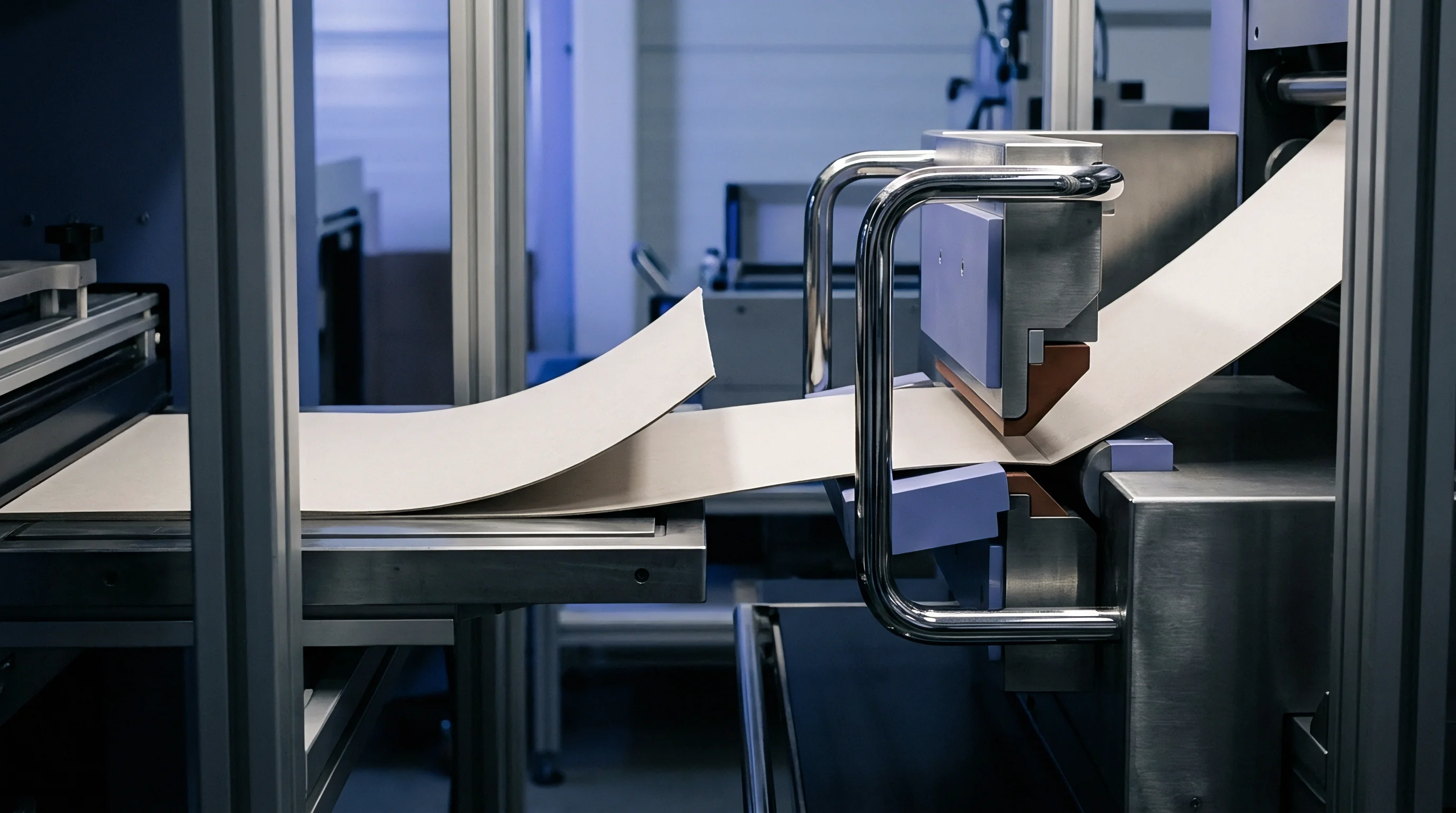
Substrate thickness and film parameters determine the structural channel dimensions necessary to avoid fiber fracture during folding. Precise measurement of composite sheet caliper forms the baseline for all die tooling setup calculations. A common error on converting floors involves selecting creasing matrixes based solely on nominal paperboard grammage while failing to include the additional thickness contributed by surface lamination films, barrier coatings, and adhesive layers.
Worked Strain Energy and Geometry Model
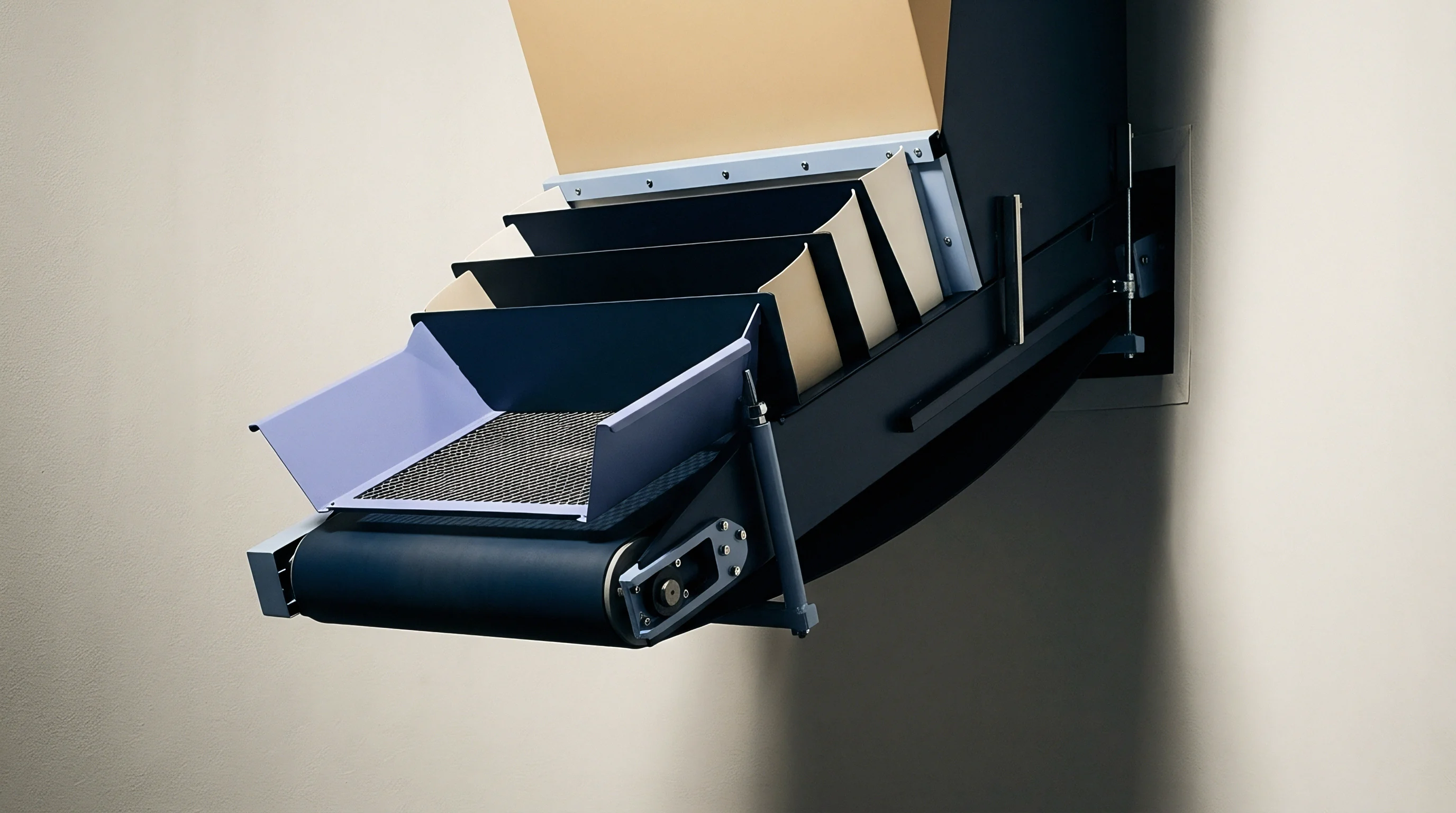
Mathematical modeling of the score deformation zone requires quantifying both elastic recovery and irreversible plastic displacement. Consider a typical premium folding carton specification: a 350-micrometer (0.350 mm) solid bleached board laminated with a 15-micrometer (0.015 mm) gloss BOPP film utilizing a 2-micrometer adhesive layer. Total composite thickness measures exactly 0.367 millimeters.
The job runs on a flatbed die-cutter utilizing a 2-point (0.71 mm) steel creasing rule.
Fiber stiffness governs score formation. Applying the established channel geometry formula yields the required matrix channel width:
W = 1.5 × (0.367 mm) + 0.71 mm = 0.550 mm + 0.71 mm = 1.260 mm
Standard commercial matrix offerings provide discrete channel widths in steps of 0.10 millimeters. Selecting a standard 1.20-millimeter matrix creates an under-sized seat condition where composite clearance is reduced by 0.060 millimeters. This clearance deficit increases peak mechanical strain energy by approximately 22 percent according to the strain energy relationship:
U_strain = 0.5 × E_composite × ε^2 × V_zone
where E_composite represents the effective flexural modulus of the film-board assembly, ε represents localized engineering strain, and V_zone is the physical volume of the deformation region. The elevated strain forces the outer BOPP film beyond its ultimate tensile limit, triggering micro-fractures along the score line during carton squaring on the packaging line.
Commercial Cost Impact of Matrix Selection
Tooling decisions directly affect sheet spoilage rates and job setup duration across high-speed packaging runs. Specifying premium composite-base or steel-base matrixes increases initial tooling consumables expense from approximately $0.80 per meter to $2.20 per meter. For a multi-up die layout requiring 45 meters of creasing matrix, consumable cost rises from $36.00 to $99.00 per make-ready.
However, choosing incorrect plastic-base matrixes that deform premature under platen pressure creates score instability across the run. A zero point five percent increase in sheet spoilage due to film splitting on a 100,000-sheet run of high-end laminated packaging equates to 500 wasted sheets. At a production cost of $0.45 per finished sheet, total scrap costs reach $225.00, completely wiping out the initial savings gained by purchasing cheaper matrix consumables.
A channel width mismatch of 0.10 millimeter increases score line surface film failure rates from 0.2 percent to 4.8 percent on 400-micrometer board runs.
- Channel Width Verification uses optical measuring microscope checks against the combined caliper of paperboard and surface laminates.
- Matrix Base Radius Selection prevents shear stress spikes along the matrix base outer margin under continuous press operation.
- Adhesive Backing Heat Resistance prevents matrix migration across hot platen environments during extended production runs.
| Rule Thickness (pt / mm) | Selected Channel Width (mm) | Matrix Channel Depth (mm) | Effective Clearance Ratio | Calculated Peak Shear Strain | Crease Quality Grade |
|---|---|---|---|---|---|
| 2 pt / 0.71 mm | 1.10 | 0.35 | 0.78 | 0.145 | Unacceptable (Film Splitting) |
| 2 pt / 0.71 mm | 1.20 | 0.35 | 0.92 | 0.108 | Marginal (High Bending Resistance) |
| 2 pt / 0.71 mm | 1.30 | 0.35 | 1.06 | 0.076 | Optimal (Clean Hinge Formation) |
| 3 pt / 1.05 mm | 1.60 | 0.40 | 1.15 | 0.062 | Optimal (Wide Flat Bead) |
Specifying DIN 53121 bending resistance compliance in packaging procurement contracts binds matrix selection to measured flexural stiffness limits rather than operator visual checks.