Dynamic Shear Stress Thresholds during High Speed Polyolefin Film Slitting Operations
Dynamic shear stress must exceed the polyolefin adiabatic yield threshold via precise knife clearance to eliminate edge drawing, micro-tears, and slitting dust.


Severance
Slitting high-tenacity polyolefin film above 600 meters per minute shifts the failure mode from clean fracture to ductile rupture. The converting line running oriented polypropylene or high-density polyethylene film subjects the cut boundary to rapid displacement rates. When deformation rates accelerate beyond the polymer relaxation spectrum, the strain state localizes along a narrow shear band.
Razor, shear, and score configurations alter the stress tensor across this zone. Razor geometry concentrates pure tensile tearing ahead of the blade apex. Rotary shear slitting combines out-of-plane compression with dynamic shear loading.
The distinction governs whether the split web maintains structural integrity or sheds micro-debris across downstream nip rollers.
The transition from a stable shear plane to catastrophic edge tearing correlates with the dynamic shear yield stress of the polyolefin substrate. Uniaxial tensile data gathered at quasi-static strain rates of 0.01 per second underestimates the force required to part biaxially oriented polypropylene during production. Polypropylene exhibits strong strain rate sensitivity.
As line speed increases from 100 meters per minute to 800 meters per minute, the strain rate inside a five-micrometer shear band reaches 100,000 per second. At these velocities, polymer chain disentanglement ceases. The material responds with elevated elastic resistance, followed by severe adiabatic heating within the slip plane.
Dynamic shear yields exceed 85 MPa when effective strain rates pass 50,000 per second under ambient web temperatures of 23 degrees Celsius.
Converters frequently observe edge hairs, curved slivers, and angel hair when slitting biaxially oriented polypropylene below critical shear stress thresholds. This debris generates electrostatic clinging on the film surface, migrating into gravure print units and laminating stations. The particles destabilize adhesive laydown, creating pinholes in high-barrier metallized film structures.
Slitting is the final mechanical transformation before slung roll packaging. Tool wear or misalignment that drops dynamic stress below the clean separation threshold ruins thousands of meters of film within minutes.
Mechanics of Localized Plastic Flow
Deformation begins as the knife penetration induces localized compression, establishing triaxial stress states in the polyolefin matrix. Microvoids initiate around polymer spherulites and inorganic slip additives like synthetic silica. Under quasi-static loading, these voids dilate slowly, allowing drawing, fibrillation, and extensive yielding before separation.
At commercial slitting speeds, void coalescence occurs within microseconds. The energy of plastic deformation converts into thermal energy faster than the thermal conductivity of polyolefin films (roughly 0.12 to 0.22 Watts per meter Kelvin) can dissipate it. The local temperature in the shear zone spikes past the crystalline melting point, which sits around 165 degrees Celsius for polypropylene and 130 degrees Celsius for polyethylene.
When this localized thermal spike takes place, the polymer yields along a razor-thin path, separating cleanly with minimal tensile elongation along the roll edge. Insufficient local shear stress prevents the material from reaching this adiabatic melting threshold. Instead, the substrate draws out into elongated filaments that fray and tear raggedly.
Setting blade velocity, knife overlap, and rake angles correctly ensures that the shear zone achieves the stress required to trigger rapid ductile failure rather than messy drawing.
Tooling
Industrial rotary slitting assemblies employ an upper male knife and a lower female anvil ring. Precise mechanical engagement determines the force balance transferred through the web. Three primary variables dictate the shear stress field: horizontal blade clearance, vertical overlap depth, and the cant angle between the rotating blade planes.
Improper management of these geometric tolerances alters the applied force from controlled dynamic shear to uncontrolled lateral bending, causing premature edge tearing.
Horizontal clearance acts as the most sensitive variable in rotary shear converting. Standard operating procedures target a clearance between 5 percent and 10 percent of total film thickness. For a 12-micrometer biaxially oriented polypropylene film, this translates to a lateral gap between 0.6 and 1.2 micrometers.
When clearance widens past 15 percent, the film draws between the knife flanks instead of parting under dynamic shear. The material undergoes transverse stretching, creating an upturned, stretched lip along the edge of the roll. Conversely, zero clearance or negative interference causes blade face scuffing, severe frictional heating, blade chipping, and rapid edge deterioration.
| Film Substrate | Caliper (microns) | Cant Angle (degrees) | Horizontal Gap (microns) | Vertical Overlap (mm) | Target Line Speed (m/min) |
|---|---|---|---|---|---|
| Biaxially Oriented Polypropylene (BOPP) | 12 | 0.20 to 0.35 | 0.8 to 1.2 | 0.30 to 0.50 | 600 to 1000 |
| Biaxially Oriented Polypropylene (BOPP) | 30 | 0.25 to 0.40 | 1.8 to 2.5 | 0.50 to 0.75 | 500 to 850 |
| Cast Polypropylene (CPP) | 50 | 0.30 to 0.50 | 3.5 to 5.0 | 0.60 to 0.90 | 350 to 600 |
| Machine Direction Oriented HDPE | 20 | 0.20 to 0.35 | 1.2 to 1.8 | 0.35 to 0.55 | 450 to 750 |
| Cast Low-Density Polyethylene (LDPE) | 70 | 0.40 to 0.60 | 5.5 to 7.0 | 0.80 to 1.20 | 300 to 500 |
Vertical overlap governs the penetration arc and dwell time of the blade inside the web profile. Excessive overlap forces the slit edge to drag along the body of the upper knife, generating frictional heat and secondary scuff marks. Overlap maintained between 0.3 millimeters and 0.8 millimeters restricts contact strictly to the cutting apex, minimizing lateral deflection.
Cant angle, defined as the inward inclination of the male knife toward the female anvil, generates the necessary side-force bias. A cant angle between 0.20 and 0.50 degrees maintains positive point-contact engagement, compensating for dynamic runout at high rotational speeds.
Blade Composition and Boundary Wear
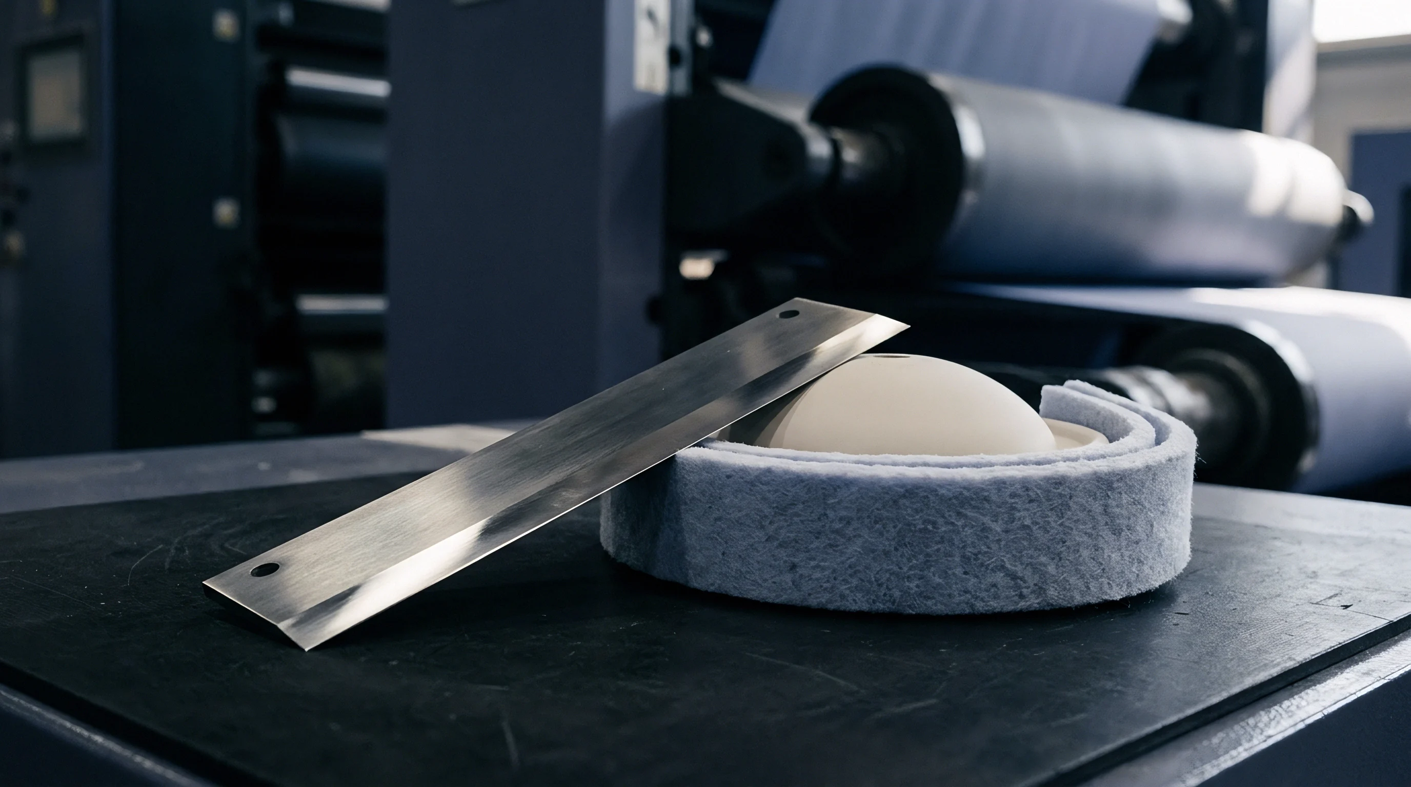
Tooling materials determine how long cutting geometry holds up against abrasive slip additives. High-carbon tool steels degrade within consecutive shifts under continuous multi-kilometer runs. Modern slitting sections deploy sub-micron tungsten carbide grades or ceramic-coated tool matrices to mitigate rapid edge rounding.
- Tungsten carbide alloys with 6 to 9 percent cobalt binder provide the mechanical stiffness needed to prevent tool deflection under high transverse web tension.
- Titanium carbo-nitride physical vapor depositions lower the friction coefficient to 0.2, reducing boundary temperatures and polymer resin adhesion along the blade flank.
- Zirconia-toughened alumina ceramics deliver high edge retention without metallic contamination, serving food packaging film converting lines where metal shavings create contamination liabilities.
- Cryogenically treated powdered steels balance fracture toughness and wear resistance, offering resistance to edge micro-chipping caused by anvil runout vibrations.
As the cutting radius of the upper blade wears beyond five micrometers, cutting forces rise sharply. Rounded tool edges displace web material forward via compression rather than severing it through concentrated shear. The polymer experiences high drawing strains, leaving behind beaded rims that disrupt winding uniformity and cause roll telescoping on slitter-rewinders.
Re-grinding schedules depend directly on edge profile inspection. Optical measuring microscopes check that rake angle variations remain under 0.5 degrees and cutting tip radii stay below three micrometers. Tool holders with pneumatic side-load control deliver repeatable contact forces between 15 and 40 Newtons.
Mechanical springs lose tension over time, letting blades push apart under lateral film tension and causing slitting defects across high-speed runs.
Rheology
Polyolefin behavior during high-velocity cutting depends on polymer rheology and solid-state viscoelasticity. Semi-crystalline polyolefins possess distinct crystalline and amorphous phases. At ambient production temperatures, amorphous domains in polypropylene sit near their glass transition point, which ranges from negative 10 to zero degrees Celsius.
Amorphous domains in polyethylene operate well above their glass transition, which sits near negative 110 degrees Celsius. These differing thermal baselines dictate how polymers absorb and relax strain during cutting.
High deformation rates truncate molecular relaxation processes. When the slitting timescale is shorter than the reptation time of entangled polymer chains, the material exhibits high dynamic moduli. The Deborah number quantifies this response, defined as the ratio of polymer relaxation time to the characteristic process timescale.
As web speeds push past 500 meters per minute, the deformation event occurs over microsecond windows, driving the Deborah number above unity. Under these regimes, the polymer cuts like a rigid solid rather than an elastic fluid.
DIN 53455 tensile protocols run at standard laboratory pull rates underestimate high-speed edge shear stress by up to 340 percent.
Chain orientation introduces profound directional variance. Biaxially oriented films show balanced mechanical characteristics, while cast films display distinct machine and transverse direction disparities. Machine-direction-oriented films exhibit tight polymer alignment parallel to the slitting path.
Slitting along the orientation axis requires less energy because crack propagation follows fibrillar boundaries. Slitting perpendicular to the orientation plane forces the tool to sever primary covalent backbones, demanding higher shear stress to achieve separation.
Viscoelastic Dissipation across High Strain Regimes
Strain rate hardening acts as a protective mechanism until the dynamic stress threshold is breached. When shear strain rates surpass 10,000 per second, effective yield stress scales with the logarithm of the strain rate, following Eyring transition-state kinetics. Activation volume calculations show that cooperative chain movement drops under high stress.
Deformation localizes within narrow slip bands rather than distributing through the bulk web.
Polymer morphology influences the width of these localized shear bands. Resins with high polydispersity indices and broad molecular weight distributions generate wider deformation zones, which can produce rough, scalloped cut edges. Resins with narrow molecular weight distributions, such as metallocene-catalyzed polyethylenes, concentrate strain into tighter zones.
This tight localization produces clean edge geometries at speeds up to 1,000 meters per minute, provided web tension prevents cross-directional fluttering.
Crystallinity fractions directly govern cut quality. High-crystallinity polypropylene homopolymers, with crystallinity levels exceeding 65 percent, separate with clean, glassy fractures under sharp shear knives. Lower-crystallinity copolymers containing ethylene co-monomers retain significant ductility even under high strain rates.
These softer copolymers draw out during cutting unless blade clearance is narrowed and web chilling is applied to restrict drawing.
Flaw
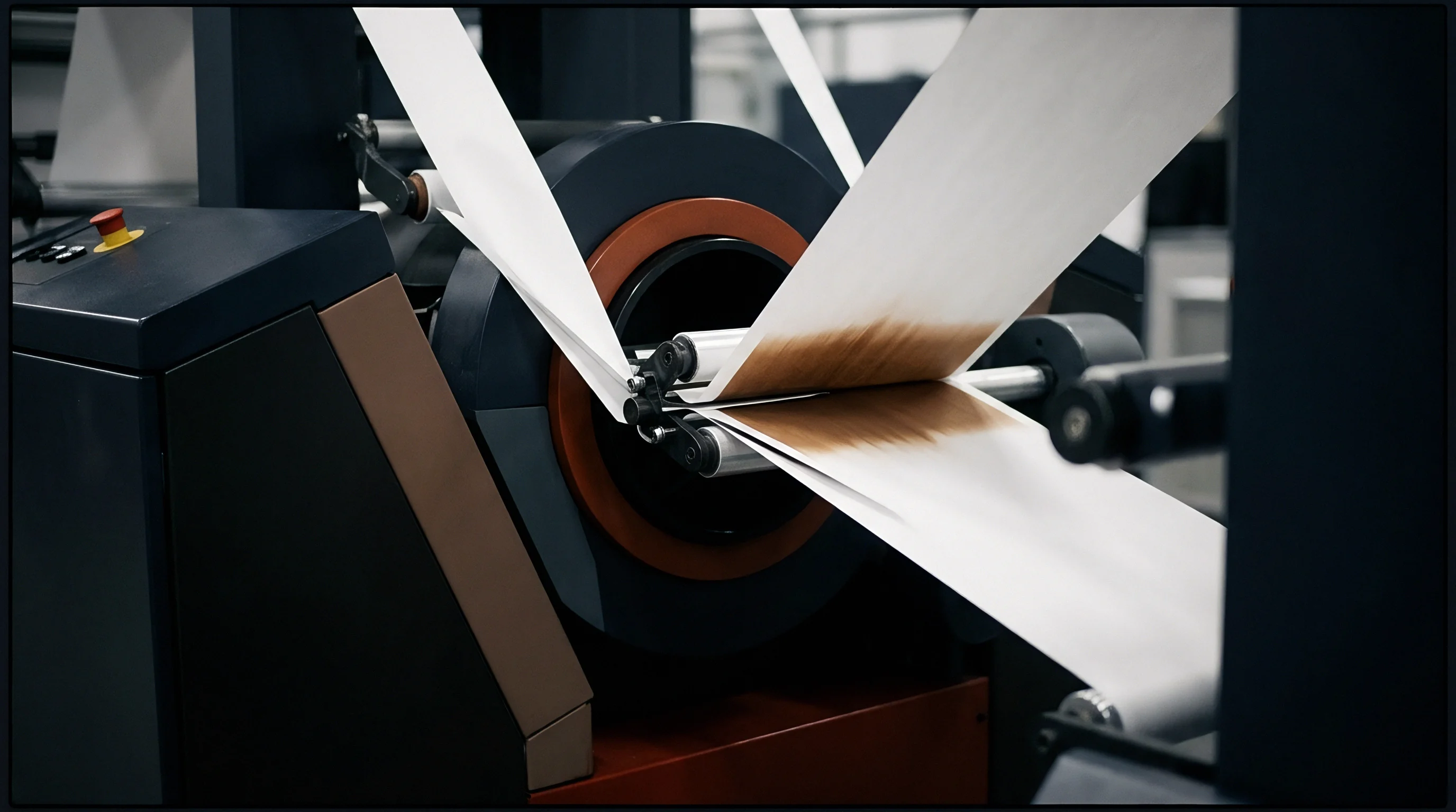
Edge defects generated by sub-optimal slitting mechanics disrupt both converting productivity and the integrity of the finished packaging material. Microscopic fractures, localized plastic draw lips, micro-cracks, and slitting dust accumulate on winding rolls, initiating systemic defects during storage and high-speed unwinding. Identifying these defects under scanning electron microscopy clarifies the mechanical failures occurring at the slitting point.
Edge beading presents as a thickened rim along the cut perimeter of the slit polyolefin roll. This defect arises when excessive tool clearance or dull blade profiles heat the polymer above its melting point without driving complete fracture. The melted resin pools along the edge and cools into a continuous, heavy bead.
When wound onto finished cores, these beads cause high localized radial pressure. The outer edges of the roll pack tightly while the roll center sags, creating uneven winding tension, bagginess, and web tracking errors in multi-pass converting machinery.
Per ASTM D882 testing protocols, a single five-micrometer edge micro-notch reduces roll web break resistance by over 45 percent under dynamic web tension.
Micro-notches along the slit edge introduce severe stress concentrations. Polyolefins are sensitive to notch propagation, particularly under high web tensions. A single five-micrometer tear can drop tensile fracture strength substantially.
When the slit roll unwinds on subsequent gravure printing or extrusion coating lines, dynamic tension spikes trigger web breaks, causing unplanned line shutdowns, material scrap, and extensive downtime.
Dust Generation and Mechanical Delamination
Slitting dust consists of loose polymer chips and fibrils ranging from 0.5 to 50 micrometers in size. This debris breaks free when the applied stress fluctuates around the dynamic shear threshold, causing erratic cycling between ductile shear and brittle tensile tearing. The resulting dust coats guide rollers, contaminates corona treatment stations, and settles onto printed substrates.
- Fibrillar debris formation occurs when low-overlap tools tear the final ligament of the web instead of shearing it cleanly through the thickness.
- Corona discharge pinholing happens as airborne polymer dust lands on treating rolls, arcing under high voltage and burning micro-holes through barrier films.
- Extrusion coating voiding occurs when loose polyolefin particles prevent hot tie-layer resins from contacting treated film surfaces.
- Telescoped roll collapse results from air entrapment and low friction when slitting dust reduces the coefficient of friction between winding film wraps.
Multilayer barrier films present complex slitting challenges. When co-extruded films contain incompatible polymer layers, such as polypropylene laminated to polyamide or ethylene vinyl alcohol, different layers respond differently to applied shear stress. The polyolefin skin may yield via ductile drawing while the barrier core fails through brittle fracture.
Mismatched mechanical responses can cause edge delamination. The separated layers let ambient oxygen and moisture enter the cut edge, compromising barrier integrity before food packaging sterilization cycles.

Calculation
Predicting dynamic shear stress values enables proactive converter optimization of machine parameters, avoiding reactive adjustments on the plant floor. Dynamic shear stress depends on web tension, film thickness, cutting force, knife contact area, and line velocity. Resolving these variables into practical equations allows technical personnel to configure slitting lines with confidence.
The effective shear stress during rotary slitting can be derived from the resultant mechanical cutting force split into normal and tangential components. Dynamic shear stress, represented by the Greek letter tau, equals the tangential force divided by the instantaneous shear contact area. The tangential force correlates with machine drive power and web tension, while the contact area depends on tool overlap, knife blade radius, and substrate caliper.
Worked Operational Scenario
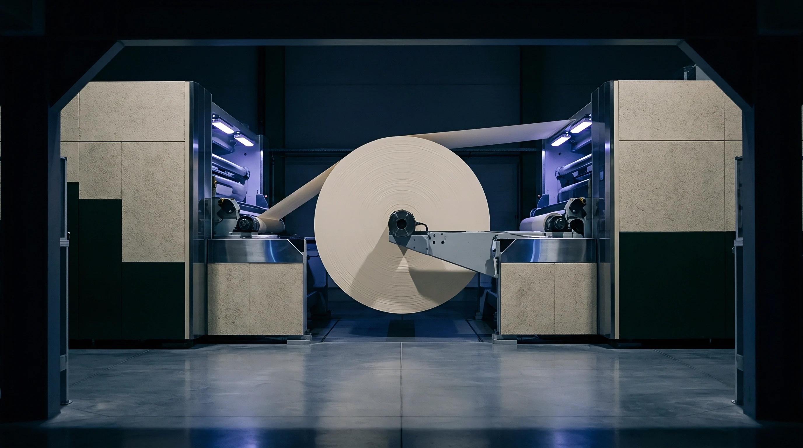
Evaluating a high-speed production run running biaxially oriented polypropylene packaging film demonstrates these engineering calculations. Consider a 1,000-millimeter web slit into multiple ribbons across an automated turret winder under steady-state running conditions:
- Operating line velocity runs at 800 meters per minute (13.33 meters per second).
- Substrate characteristics consist of 20-micrometer biaxially oriented polypropylene with a density of 0.905 grams per cubic centimeter.
- Operating web tension holds at 40 Newtons per meter of web width.
- Rotary knife overlap depth is set to 0.40 millimeters with a blade radius of 75 millimeters.
- Measured horizontal cut zone width spans 12 micrometers under high-speed video capture.
The arc length of contact along the rotating blade profile can be calculated from the blade radius and vertical overlap depth. Contact arc length equals the square root of twice the product of blade radius and overlap depth. For a 75-millimeter radius and a 0.40-millimeter overlap, this calculation yields an arc length of 7.75 millimeters.
The instantaneous contact area during cutting equals this arc length multiplied by the film thickness of 0.020 millimeters, yielding an effective area of 0.155 square millimeters.
Piezoelectric load cell measurements show an effective tangential cutting force of 14.5 Newtons acting on the web ribbon during steady cutting. Dividing this force by the instantaneous contact area yields an applied dynamic shear stress of 93.5 Megapascals. The shear strain rate within the 12-micrometer deformation band equals web velocity divided by deformation width, producing a strain rate of 1,110,000 per second.
Material testing shows that at strain rates above 1,000,000 per second, the dynamic shear threshold of this oriented polypropylene grade sits at 88 Megapascals. The operating shear stress of 93.5 Megapascals safely exceeds this minimum threshold, confirming the process operates within the clean fracture regime. If line speed drops to 300 meters per minute while tool geometry remains fixed, the strain rate declines to 416,000 per second.
At this lower speed, the dynamic shear threshold falls to 76 Megapascals, yet the tangential cutting force drops disproportionately to 9.8 Newtons. This results in an operating stress of only 63.2 Megapascals, which falls below the required threshold, causing edge drawing and debris accumulation.

Protocol
Maintaining consistent cut quality at high web speeds requires rigorous setup and calibration routines. Ad-hoc blade positioning and unmetered pneumatic loading inevitably lead to quality failures, web tears, and early knife wear. Standardized maintenance procedures ensure process reliability across multi-shift converting operations.
Setup procedures begin with runout verification of the lower female anvil shaft. Using dial test indicators with 0.5-micrometer graduations, technicians measure total radial and axial runout along the full shaft length. Total indicated runout should not exceed three micrometers at any point.
Excessive runout causes the upper male knife to cycle between over-engagement and under-engagement with every rotation. This variation creates oscillating shear conditions that show up as periodic scalloped edge patterns on rewound rolls.
Line Bring-Up and Knife Phasing
The sequence for setting rotary tooling tolerances must follow strict mechanical steps:
- Lower female anvil rings are locked to the lower drive shaft using torque wrenches calibrated to manufacturer specifications to prevent shaft distortion.
- Upper knife holder assemblies are secured to the dovetail cross-beam, using micrometer depth gauges to establish baseline cross-machine positions.
- Horizontal blade clearance is set using precision brass feeler gauges or non-contact optical sensors, locking side-play tolerances within 5 to 10 percent of film thickness.
- Vertical blade overlap depth is set using depth micrometers, indexing the male blade downward until the specified overlap registers relative to the female anvil shoulder.
- Pneumatic side-load lines are purged and pressurized, using digital pressure gauges to verify target engagement force across every slitting station.
- The line is run at an idle speed of 50 meters per minute for 30 seconds to inspect blade tracking before introducing production web tension.
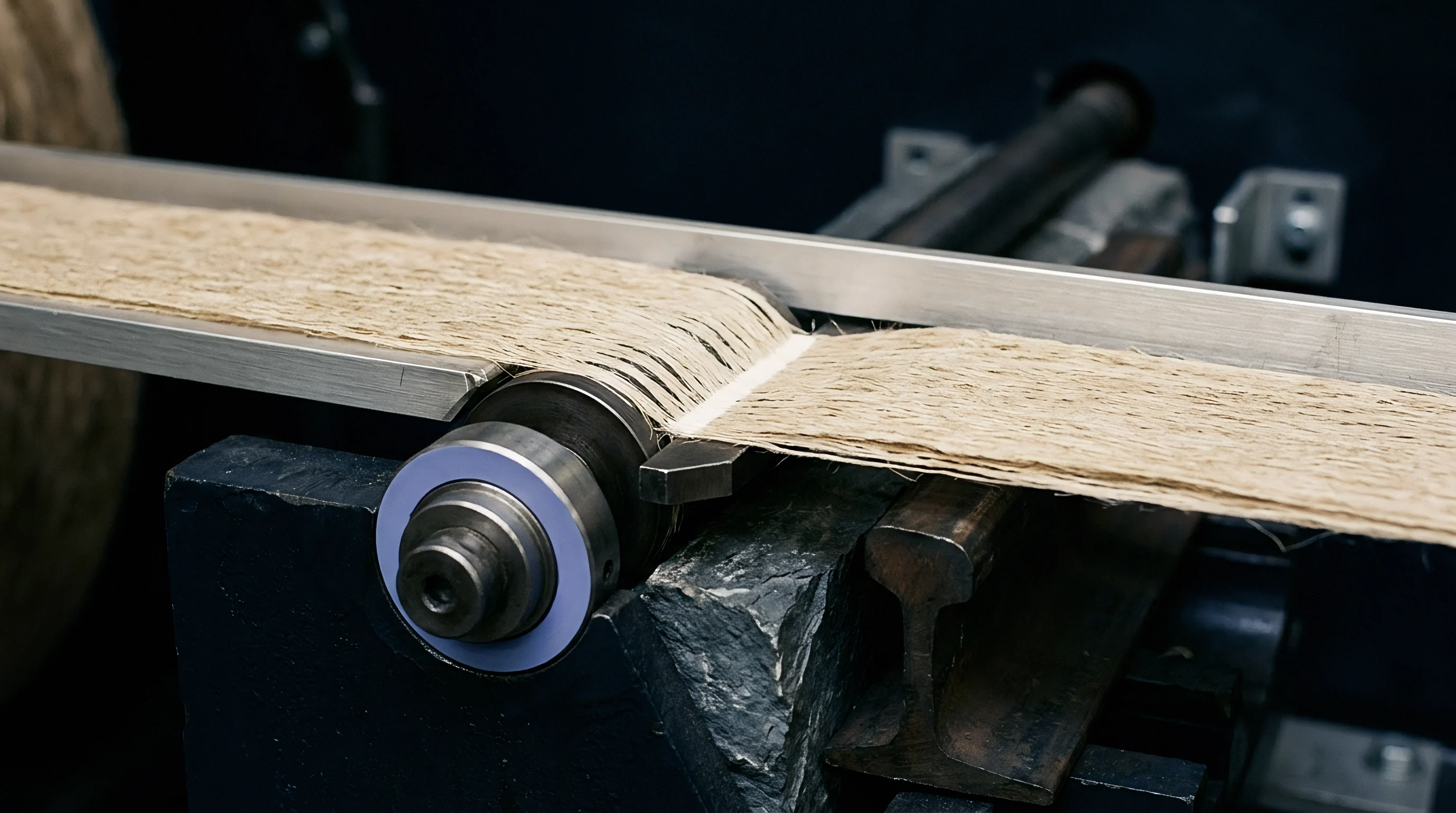
In-line optical monitoring systems verify cut quality continuously across long production runs. High-resolution line-scan cameras positioned down-web from the slitting section illuminate the cut edges using high-intensity stroboscopic backlighting. Optical recognition algorithms track edge profile variations in real time, detecting micro-serrations, drawing lips, and slitting dust before rolls move to palletizing.
When edge deviations exceed eight micrometers, the monitoring system alerts operators to inspect knife wear or adjust side-load pressures.
Margin
Slitting performance directly impacts converter profitability and operational costs. Defective roll edges drive significant internal scrap, customer rejections, and warranty claims. In high-volume flexible packaging operations, converting margins depend on yield efficiency, making scrap reduction a vital financial priority.
Edge trim waste represents a steady material cost on slitting lines. While primary web edge trimming is required to remove cast edges or tenter clips, excessive trim widths waste sellable film. A line running 12-micrometer biaxially oriented polypropylene at 750 meters per minute with 25-millimeter trim widths per side converts 18 kilograms of polymer resin into low-value trim every hour.
Upgrading to high-rigidity slitting holders with closed-loop pneumatic cant systems allows trim width reduction to 10 millimeters per side, capturing significant material savings annually across continuous operating shifts.
| Failure Mode | Root Mechanical Cause | Production Loss Mechanism | Estimated Scrap Rate (%) | Landed Cost Impact (EUR/tonne) |
|---|---|---|---|---|
| Edge Beading | Excess horizontal gap and blade face dragging | Roll blocking, baggy edges, print register drift | 2.5 to 4.0 | 65 to 105 |
| Slitting Dust Debris | Sub-threshold dynamic shear stress cycling | Coating voids, gravure cylinder clogging | 1.5 to 3.0 | 40 to 80 |
| Edge Notch Rupture | Knife micro-chipping and anvil runout spikes | Catastrophic high-speed web breaks on downstream lines | 3.0 to 6.5 | 80 to 170 |
| Layer Separation | Mismatched shear rates across co-extruded barrier layers | Loss of barrier hermeticity, flexible pouch leakers | 4.0 to 8.0 | 110 to 220 |
Tooling replacement costs are minor compared to the operational expense of unscheduled downtime. High-grade tungsten carbide blades cost more than carbon steel options, but they deliver four to eight times the service life between re-grinds. Investing in quality tooling pays back quickly by preventing line stoppages, reducing make-ready times, and eliminating salvage rewinding passes.
Can Line Velocity Compensate for Dull Blade Radii?
Increasing line speed temporarily raises local strain rates, which can partially compensate for edge rounding on worn blades. However, this adjustment carries significant process risks. Driving dull blades at elevated velocities spikes cutting temperatures and increases lateral knife deflection.
Dynamic runout vibrations worsen at higher speeds, turning stable cutting zones into erratic impacts that shorten knife life and degrade roll edge quality.
Slitter-rewinders operating near design speed limits risk generating static charges exceeding 30 kilovolts along the unshielded web path. These static fields attract slitting dust back onto the film surface while introducing safety hazards for floor operators. Proper static neutralization bars installed downstream of the slitting zone, combined with consistent knife maintenance schedules, protect film quality and operating profitability far better than uncalibrated speed increases.
Material supply agreements establish strict limits for slitting edge quality. Standard purchase terms specify that edge weave must remain below 0.5 millimeters across an entire roll, roll faces must stay flat within 1.0 millimeter, and rolls must be completely free of visual angel hair debris. Violating these standards allows downstream packaging plants to reject full material lots, leaving converters liable for logistics costs and production downtime penalties.