Non Contact Laser Profiling Verification Baseline Setup in Board Converting
Establish an isolated vacuum datum and calibrate 405-nanometer sensors to eliminate sub-surface scattering errors during board crease verification.

Optics
Board converting lines use non-contact laser triangulation sensors to measure surface topographies, crease profiles, and score geometries without compressing fibrous plies. The setup projects a focused semiconductor laser beam at a set standoff distance onto the board web, sending the diffuse reflection through a receiver lens array to a position-sensitive detector or CMOS sensor grid. Light penetrating cellulose substrates creates chromatic and volumetric dispersion, shifting the apparent optical plane below the true physical surface.
Under 660-nanometer red laser light, virgin solid bleached sulfate boards show sub-surface scattering depths between 12 and 45 micrometers; unbleached kraft liners keep photon penetration under 8 micrometers due to lignin absorption.
Surface absorption and diffuse scattering differ widely among coated, uncoated, and recycled grades. In setting up the optical receiver, technicians balance sensor integration time against web speed. Blue laser diodes at 405 nanometers sharply cut sub-surface penetration on bleached chemical pulp, cutting optical centroid uncertainty fourfold compared to standard red diodes.
A 405-nanometer blue diode limits beam penetration to 3.2 micrometers on clay-coated solid bleached board conditioned at 23 degrees Celsius and 50 percent relative humidity.
Specular reflection from high-gloss barrier coatings like extruded polyethylene or UV-cured overprint varnishes can saturate the receiver and bloom the signal. Sensor firmware prevents clipping with dynamic power loops that adjust laser output on a microsecond scale. Steep crease shoulders also create occlusion zones in standard triangulation geometry, though a dual-receiver sensor head resolves these blind spots by taking elevation readings from opposing 45-degree angles.
Triangulation accuracy across folding boxboard depends heavily on sensor wavelength, spot geometry, and beam polarization relative to machine-direction fibers.
| Substrate Grade | Caliper (µm) | Grammage (g/m²) | Laser Wavelength (nm) | Scattering Depth (µm) | Z-Axis Resolution (µm) |
|---|---|---|---|---|---|
| Solid Bleached Sulfate (SBS) | 450 | 310 | 660 (Red) | 38.4 | 2.8 |
| Solid Bleached Sulfate (SBS) | 450 | 310 | 405 (Blue) | 5.1 | 0.6 |
| Folding Boxboard (FBB) GC1 | 520 | 300 | 405 (Blue) | 4.8 | 0.7 |
| Coated Recycled Board (CRB) | 480 | 350 | 405 (Blue) | 3.2 | 0.8 |
| Unbleached Kraft Liner | 380 | 275 | 660 (Red) | 7.6 | 1.2 |
Uneven mineral pigment across double-coated board alters local diffuse reflectivity, producing small signal fluctuations that equipment vendors often dismiss as background substrate noise.
Bed
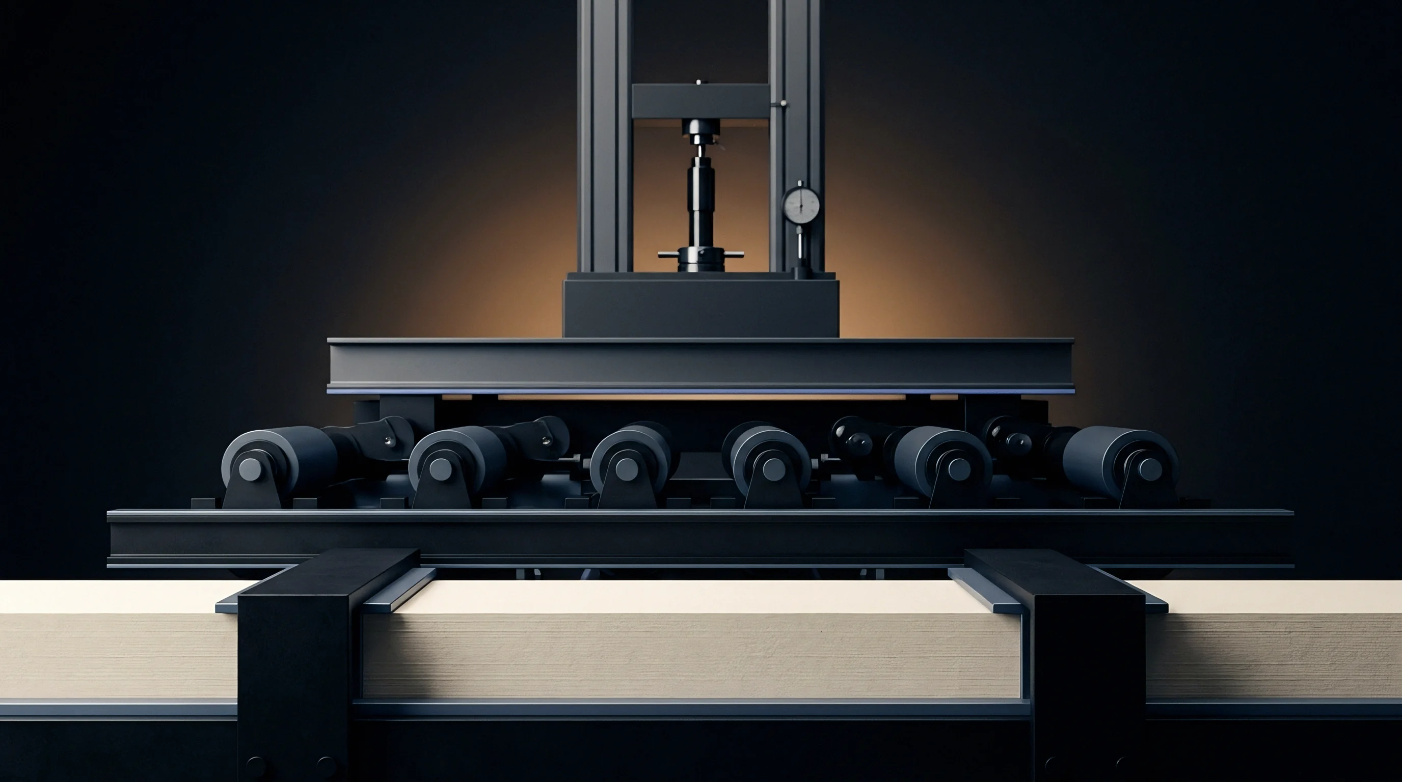
Mechanical stability under the optical scanning zone determines whether laser displacement records true board contours or machine vibration. Platen die-cutters and folder-gluers create strong harmonic excitation during operation, with vibrations reaching 60 to 180 micrometers in amplitude between 15 and 250 Hertz. Mounting the laser assembly to a decoupled granite or cast-iron bridge isolates the sensor head from frame shudder.
Reliable baseline measurements demand a vacuum datum platen ground flat to within 2.5 micrometers per 300 millimeters of span.
Vacuum hold-down zones hold warped sheets flat against the reference platen without adding cross-directional tension. If suction varies across the surface, sheet flutter degrades the baseline and produces false thickness readings across score lines.
Uneven vacuum distribution creates micro-pockets that distort board baseline profiling across rotary die-cutting stations.
Operators build rigid datum surfaces using platen alloys and vacuum hole layouts that stop sheets from dimpling under strong suction. The mounting assembly relies on several core components:
- Granite mounting bridges isolate optical triangulation heads from frame harmonics using high internal damping.
- Ceramic vacuum platens maintain flatness despite ambient temperature shifts on high-speed folder-gluer lines.
- Micro-machined suction orifices avoid sheet dimpling on light folding boxboard while pulling uniform suction.
- Pneumatic edge hold-down clamps flatten curled multi-ply blanks against the datum plane before scanning starts.
Warp and edge curl in recycled paperboard can lift sheets off the measurement datum. Because recycled fibers expand readily with moisture, sheets curl whenever relative humidity strays more than 5 percent from the mill packaging baseline. Vacuum manifolds need to pull at least 40 kilopascals of negative pressure to hold 600-micrometer coated recycled board flat.
If the hold-down fails to pull the blank flush against the datum, the profiler registers false baselines, driving unnecessary tooling adjustments and wasting hundreds of production hours.
Calibration
Reference artifacts provide traceable baselines for optical profilometry in converting environments. Standard procedures rely on optical-grade silicon carbide step gauges, matte ceramic reference blocks, and calibrated chrome-on-glass targets to establish height and lateral dimensions under ISO 25178. Factory light, dust, and temperature shifts all drift baseline readings over time, so daily checks measure an optical flat certified within 0.05 micrometers to track receiver drift and diode aging.
Triangulation sensors show thermal zero-point drift averaging 1.5 micrometers per degree Celsius of temperature change. Engineers address this with temperature-compensated mounts and positive-pressure air curtains around the optical path. Filtered, dry air keeps paper dust from settling on receiver lenses.
ISO 25178 part 604 defines non-contact sensor noise thresholds, ensuring measurement errors stay below 0.5 percent of nominal board caliper.
Gauge repeatability and reproducibility studies separate instrument noise from board surface variations. Daily baseline calibration follows a set sequence:
- Thermal stabilization lets the optical sensor and laser diode reach thermal equilibrium over a twenty-minute warmup cycle.
- Reference artifact scanning records absolute Z-axis height against an ISO-traceable 500-micrometer ceramic step block.
- Lateral scaling verification checks X-axis and Y-axis distortion against a calibrated glass grid target.
- Optical noise quantification reads static output across an optical black reference flat to confirm sensor electronic stability.
- Substrate zero compensation measures diffuse baseline on an uncreased section of the target board lot to zero out coating scattering depth.
Calibration records support compliance with supply contracts. Section 4.2 of DIN 55437-1 requires profile measurement tools to maintain a gauge uncertainty ratio below one to ten against total score tolerance bands.

Deformation
Die-cutting and scoring transform flat multi-ply board into cartons through controlled internal delamination. A precision matrix forces board into a channel, stretching the liner while breaking internal fiber bonds in a localized delamination zone. Non-contact laser profiling captures this geometry in dense three-dimensional point clouds, measuring bead height, groove penetration, symmetry, and shoulder roll-off.
These dimensions directly indicate how the carton will behave on automated erection equipment.
Creasing rule width, channel depth, and moisture levels together govern bead geometry. If board moisture falls below 6.0 percent, outer liners crack on cross-direction scores, showing up in laser scans as fine split ridges along the crease apex.

What Dynamic Displacement Limits Crease Depth Precision?
Laser triangulation heads sampling at 100 kilohertz capture profiles on carton blanks moving at 300 meters per minute. Vibration and web flutter introduce surface artifacts that alter measured groove depths, requiring high-speed algorithms to filter out spatial noise using Gaussian regression per ISO 16610-21.
| Board Grade | Rule Thickness (pt) | Matrix Channel Width (mm) | Nominal Caliper (µm) | Bead Height (µm) | Crease Symmetry (%) |
|---|---|---|---|---|---|
| Solid Bleached Sulfate | 2.0 (0.71 mm) | 1.40 | 400 | 225 | 98.2 |
| Solid Bleached Sulfate | 3.0 (1.05 mm) | 1.80 | 600 | 340 | 97.5 |
| Folding Boxboard GC2 | 2.0 (0.71 mm) | 1.50 | 450 | 270 | 95.1 |
| White Lined Chipboard | 2.0 (0.71 mm) | 1.60 | 450 | 210 | 91.4 |
| Coated Kraft Back | 3.0 (1.05 mm) | 1.90 | 550 | 315 | 96.8 |
Crease recovery force relies on symmetrical delamination. An off-center crease rule produces skewed bead profiles, reducing carton stiffness and causing side panels to bow on high-speed gluer lines. Symmetrical beads ensure reliable opening on packaging machinery.
Settlement
Disputes between board mills, converters, and packaging plants usually focus on dimensional tolerances and converting yield. When cartons jam in loader magazines, packaging lines reject whole lots over score defects or panel bowing. Laser profiling data provides objective surface geometry files to settle these claims.
Stoppages get expensive quickly ~ high-speed pharmaceutical lines lose thousands of euros per hour when jammed.
In one commercial converting dispute, a delivery of two million pharmaceutical cartons was rejected for defective score stiffness and improper fold lines. The converter scanned 500 retained blanks from the disputed batch alongside 500 blanks from an accepted reference run using laser profiling.
| Batch Identity | Mean Bead Height (µm) | Bead Height Spread (µm) | Liner Crack Count per 1000 | Erection Force (N) |
|---|---|---|---|---|
| Accepted Reference Run | 245.2 | 12.4 | 0 | 1.42 |
| Disputed Production Lot | 182.6 | 44.8 | 28 | 2.68 |
| Recalibrated Tooling Trial | 242.0 | 14.1 | 1 | 1.45 |
Profile data showed that the disputed lot suffered from shallow matrix penetration, which reduced bead height by 62.6 micrometers and raised opening force past feeder limits. The quantitative data separated converter setup error from baseboard delamination failure. Technical purchase contracts increasingly specify laser scan baselines, setting explicit limits for crease geometry, residual score thickness, and surface roughness.
How effectively optical profiling systems can separate furnish moisture fluctuations from mechanical tooling wear on high-speed inline converting lines remains an open question.