Predictive Shear Strain Thresholds for Extruded Polyethylene Layers during Rotary Female Die Scoring
Rotary female die scoring of extruded PE layers requires limiting peak shear strain below 1.65 to prevent pinhole fracturing and barrier loss.
Film
Extruded polyolefin skins applied to solid bleached sulfate paperboard experience severe combined normal and tangential forces when passing through high-speed rotary scoring nips. Microstructural deformation within the polymer layer dictates whether the skin maintains liquid barrier continuity or suffers localized shear failure. Low-density polyethylene applied via extrusion coating forms an semi-crystalline structure characterized by spherulitic domain boundaries suspended in an amorphous polyolefin matrix.
During high-velocity scoring, stress fields concentrate at the interface between the fibrous paperboard substrate and the polymer coating. Shear forces govern deformation.
Deformation behaviour under high-velocity scoring tools depends directly on melt flow index and density parameters established during resin synthesis. Low-density polyethylenes with a melt flow index between 4.0 and 7.0 grams per ten minutes at 190 degrees Celsius under a 2.16 kilogram load demonstrate optimal drawability during extrusion coating, yielding layer thicknesses from twelve to thirty micrometres. Higher melt flow index values reduce long-chain branching entanglements, lowering the ultimate elongation at yield when the polymer experiences rapid transient deformation.

Polymer Rheology under High Strain Rates
Polyolefin coatings processed at standard extrusion temperatures exhibit non-linear viscoelastic responses during millisecond scoring contacts. Strain rate sensitivity accelerates sharply when line velocities exceed two hundred meters per minute. Rotary die engagement times often fall below two milliseconds, preventing polymer chain orientation and relaxation along stress contours.
Under these adiabatic conditions, mechanical energy converts locally into thermal energy, softening the polyolefin matrix while elevating localized plastic strain concentrations.
Extrusion cooling profiles dictate crystallite size and spatial distribution across the coating thickness. Rapid chill roll quenching produces fine spherulitic structures that distribute mechanical shear more uniformly than coarse crystallites formed during slow cooling. Polymer density shifts ductility.
Extruded coatings with densities ranging from 0.918 to 0.924 grams per cubic centimetre yield a balanced combination of tensile yield strength and shear elongation. Increasing density above 0.930 grams per cubic centimetre elevates stiffness but restricts ultimate strain capacity, accelerating crack initiation at score lines.
| Resin Type | Density (g/cm³) | Melt Index (g/10 min) | Tensile Yield (MPa) | Critical Shear Strain Limit |
|---|---|---|---|---|
| Autoclave LDPE | 0.918 | 7.0 | 9.5 | 1.85 |
| Tubular LDPE | 0.920 | 5.5 | 11.2 | 1.65 |
| Metallocene LLDPE | 0.919 | 4.2 | 12.8 | 2.10 |
| HDPE Blend (15%) | 0.932 | 3.0 | 18.4 | 1.15 |
Extrusion Process Variables and Density Limits
Chill roll quenching speeds determine the relative ratio of amorphous to crystalline domain fractions within the polyolefin barrier layer. High quench rates lock the polymer chains into an amorphous configuration that tolerates higher localized shear strain before micro-void initiation occurs. Melt temperature management during extrusion coating further impacts interfacial adhesion and coat-weight uniformity across the machine direction.
Oxidation of the molten web at the air gap creates polar carboxyl groups that bond chemically to cellulosic board fibers, anchor points that transfer shear stresses into the fibrous network during scoring.
An extruded low-density polyethylene layer of eighteen micrometres thickness reaches its ultimate shear strain limit at 1.85 when evaluated under a strain rate of 1200 reciprocal seconds at 23 degrees Celsius.
Inadequate melt oxidation weakens interfacial bonding, allowing the polyolefin layer to delaminate prematurely under female die anvil displacement. Excessive melt temperatures cause thermal degradation and chain scission, dropping polymer molecular weight and severely compromising shear strain thresholds. Machine-direction orientation developed during high-draw extrusion creates anisotropic strain resistance.
Polyolefin skins display higher ultimate strain values in the cross-machine direction, making cross-web scoring lines particularly susceptible to shear cracking when die geometry is uncalibrated. Cold web conditions reduce ductility. Increasing melt flow index reduces polymer strain resistance during rapid rotary deformation.
Crease
Rotary male scoring wheels compressing paperboard into matching female channel dies create complex strain fields across laminated polymer coatings. Penetration depth, male wheel tip radius, female groove width, and anvil nip clearance define the geometric compression profile imposed upon the composite material. As the male blade forces the paperboard substrate into the female channel, the polyolefin skin on the reverse side undergoes intense tensile-shear displacement.
Displacement fields develop rapidly as the tool edge enters the scoring cavity.
Die engagement geometry determines whether polyolefin coatings deform plastically or rupture during scoring operations. Female channel anvil design must match paperboard thickness and polyolefin layer caliper to avoid exceeding critical shear thresholds. Groove width ratios relative to substrate caliper dictate the bending radius formed at the score root.
Tight female channels concentrate shear stress at the score shoulders, while wide channels result in poor crease definition and unstable folding torque during subsequent carton erection.
Rotary Female Die Geometry and Anvil Parameters
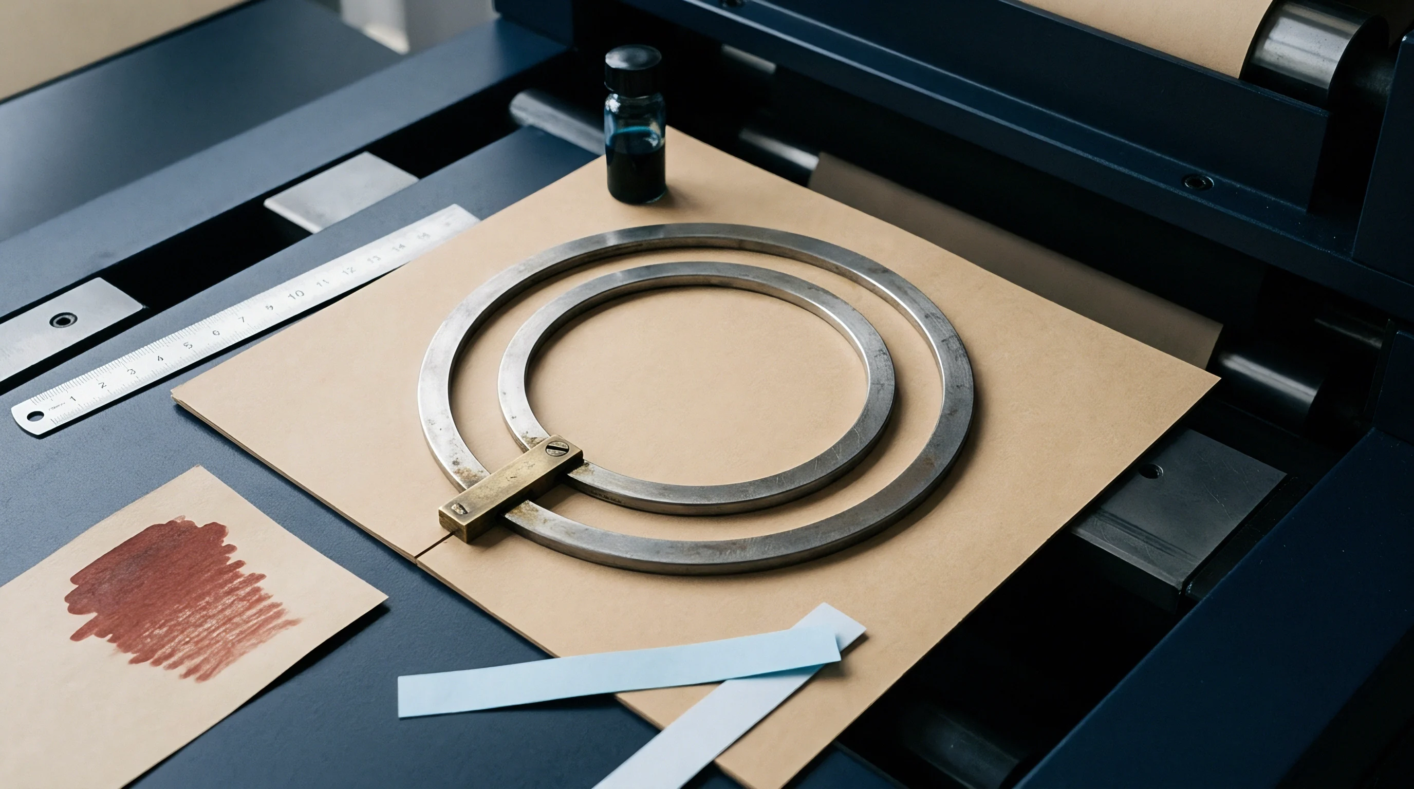
Channel depth, shoulder radius, and groove width directly govern the displacement profile enforced upon polyolefin-coated paperboard layers. Rotary scoring systems utilize hardened steel female rings featuring precision-ground grooves mounted opposite chrome-plated male score wheels. Tooling alignment controls strain.
Penetration depth controls displacement. Male rule tip radii ranging between 0.35 and 0.70 millimetres distribute compressive forces across the score root, preventing premature fiber cutting while preserving polyolefin skin continuity.
| Male Radius (mm) | Female Width (mm) | Female Depth (mm) | Penetration Ratio | Peak Shear Strain |
|---|---|---|---|---|
| 0.35 | 1.10 | 0.45 | 0.75 | 1.92 |
| 0.50 | 1.25 | 0.45 | 0.70 | 1.58 |
| 0.70 | 1.40 | 0.50 | 0.65 | 1.24 |
| 0.35 | 1.40 | 0.50 | 0.80 | 1.71 |

Nip Penetration Mechanics and Velocity Vector Dynamics
Machine operating speeds exceeding two hundred meters per minute reduce the total deformation duration to less than three milliseconds. Under these rapid engagement times, the velocity vector of the male rule edge imposes steep strain gradients across the polymer layer thickness. Shear stress concentrations peak along the female channel entry shoulders, where material experiences maximum bending curvature combined with compressive nip force.
Calibrating female anvil clearance prevents mechanical crushing of board fibers while ensuring polyolefin membrane continuity.
- Measure exact substrate caliper across three web points using a dead-weight micrometer per ISO 534 conditioning standards.
- Select female anvil ring channel width establishing a one-to-one point four ratio against total composite substrate thickness.
- Adjust male die ring nip clearance using precision feeler gauges to set exact penetration depth into the female groove.
- Execute high-speed trial run at target line velocity and extract score samples across the full web width for barrier validation.
Improper die alignment generates asymmetric strain distributions across the female channel shoulders. When the male score wheel shifts off-center by as little as twenty micrometres, local shear strain on the narrow side increases by up to thirty-five percent. This displacement spike frequently breaches the polymer’s shear yield limit, initiating micro-fractures along the inner fold line.
Extrusion coater technical representatives frequently maintain that line speed increases alter heat history and fully compensate for improper anvil channel width.


Threshold
Material failure in extruded polyolefin layers initiates when local shear strain values exceed the critical yield limits of the polymer matrix. Predictive shear strain modeling allows packaging engineers to establish precise tooling parameters before running production stock through rotary converting equipment. Hydrostatic pressure generated during die nip compression alters the classical von Mises yield criterion, increasing polyolefin resistance to shear yield under uniform compressive fields.
Yield limits bound headroom.
Microstructural failure manifests through two distinct physical mechanisms during rotary female die scoring. Shear strain accumulation leads to localized necking and thinning of the polymer membrane, ultimately causing pinhole rupture under web tension. Alternatively, interfacial shear stress exceeds the mechanical adhesion strength between board fibers and the polymer coating, triggering delamination.
Both modes ruin barrier performance and lead to liquid packaging failure.

Mathematical Strain Prediction and Yield Equations
Calculating the onset of permanent shear deformation relies upon modified Tresca and von Mises yield criteria adjusted for hydrostatic compression. The effective shear strain gamma experienced by an extruded layer inside a female die channel derives from localized displacement vectors across the coating thickness.
Effective shear strain equations incorporate score penetration depth, female channel width, and polymer coat weight. Peak effective shear strain is modeled using the following formulation:
gamma = (delta_x / t_PE) (1 + beta P_hydro)
Where delta_x represents horizontal strain displacement at the channel shoulder, t_PE represents polyolefin layer thickness, beta represents the pressure-sensitivity coefficient of polyolefin yield strength (typically 0.0025 per megapascal for LDPE), and P_hydro represents local hydrostatic compression pressure in the die nip. Microscopic fractures ruin seals.
Scoring Penetration Worked Calculation
Evaluating a typical liquid packaging board specification demonstrates how geometric variables dictate internal strain magnitudes. Take a solid bleached sulfate substrate with a total caliper of 380 micrometres coated with a 20 micrometre layer of extruded low-density polyethylene having a density of 0.920 grams per cubic centimetre. The converting line operates with a male score wheel radius of 0.35 millimetres and a female channel groove width of 1.20 millimetres at a channel depth of 0.50 millimetres.
Assume a tooling penetration depth set to 0.28 millimetres, representing a 73.7 percent penetration ratio relative to paperboard caliper. Hydrostatic nip pressure reaches approximately 18.5 megapascals at peak engagement. The horizontal strain displacement delta_x calculated at the female die shoulder equals 28.4 micrometres under these geometric constraints.
Substituting these values into the shear strain equation yields:
gamma = (28.4 / 20.0) (1 + 0.0025 18.5) = 1.42 1.046 = 1.485
For an extruded LDPE grade with a published critical shear strain threshold of 1.65 under high strain rate conditions, an effective strain value of 1.485 remains safely within stable operating limits. Increasing tooling penetration depth to 0.33 millimetres elevates horizontal displacement delta_x to 33.1 micrometres while raising hydrostatic pressure to 22.0 megapascals:
gamma = (33.1 / 20.0) (1 + 0.0025 22.0) = 1.655 1.055 = 1.746
An effective shear strain of 1.746 exceeds the polymer’s critical threshold of 1.65, triggering plastic necking and pinhole shear fracture along the score root. Excessive depth causes tear.
- Parameter Verification Check physical polymer coat weight and substrate caliper using calibrated micro-gauges prior to scoring setup.
- Strain Analysis Calculate peak effective shear strain using actual channel dimensions and verified tool engagement depths.
- Thermal Conditioning Maintain converting hall ambient temperatures at twenty-three degrees Celsius to preserve polyolefin ductility.
- Speed Modulation Adjust rotary line velocity gradually while monitoring score line barrier continuity via die-penetration tests.
A contract specification demanding zero dye penetration under ASTM F1929 forces line operators to maintain female anvil clearance within a six micrometre window.
Whether biaxial web tension applied during high-speed rewinding suppresses micro-void formation at peak shear locations remains unverified across commercial converting lines.
Audit
Verifying barrier continuity following rotary scoring requires destructive and non-destructive physical testing procedures. Visual inspection cannot identify sub-visible shear micro-cracks formed within extruded polyolefin layers along score roots. Quality assurance regimes must implement rigorous testing protocols to detect barrier breakdown before converting stock into finished liquid cartons.
Barrier failure drives scrap.
Standardized test methods apply chemical indicators, vacuum decay, or electrical impedance to locate barrier breaches created by excessive shear strain. Dye penetration testing provides rapid feedback on converting line setup, exposing pinholes and delamination channels. Advanced cross-sectional microscopy quantifies structural damage within both the paperboard fiber network and the polyolefin membrane.
Dye Penetration and Microscopic Inspection Procedures
Solution mixtures containing wetting agents and red dyes reveal sub-visible pinholes caused by excess shear strain during scoring. Testing involves applying glycol-based dye solutions along the score line for a standardized exposure duration, typically two minutes. Dye passes through polyolefin micro-cracks and stains the underlying cellulosic fibers, providing clear visual evidence of barrier failure.
Scanning electron microscopy and optical cross-sectional analysis reveal internal structural deformation within scored board samples. Microscopic examination of polished score cross-sections measures actual local wall thinning in the polyolefin skin, identifying necking regions that approach failure thresholds. Automated image analysis software quantifies polyolefin layer thickness reduction along score contours, furnishing precise data for tooling optimization.
| Test Method | Standard Designation | Detection Limit | Target Metric |
|---|---|---|---|
| Dye Penetration | ASTM F1929 | 10 µm pinhole size | Zero stain breaches |
| Crease Stiffness | TAPPI T 577 | ±1.5 mN force precision | 45% force reduction |
| Micro-Sectioning | ISO 187 Prep | 1.0 µm resolution | <30% layer thinning |
| Conductivity Test | ASTM D512 Mod | 0.1 µA current leak | <0.5 µA leakage rate |

Standardized Test Methods and Mechanical Evaluation
ASTM F1929 and TAPPI T 577 establish formal testing protocols for evaluating scoring lines on polymer-laminated packaging stock. Crease stiffness testing measures the bending force required to fold scored board to a ninety-degree angle, correlating bending resistance with score depth and polyolefin deformation. Balanced scoring produces significant bending force reduction without compromising the fluid barrier layer.
Sharper male tip radii shift polymer deformation from planar displacement to localized cutting action.
- Shear Micro-fracturing Pinholes generated along score shoulders due to local strain values exceeding polymer yield limits.
- Interface Delamination Separation between polyolefin skin and cellulosic board fibers caused by excessive interfacial shear stress.
- Crystallite Cavitation Micro-void formation within polymer spherulitic boundaries induced by high strain rate deformation.
- Pinhole Tensile Rupture Complete membrane tearing along the score root resulting from excessive male blade penetration depth.
Inserting an explicit zero-pinhole requirement under TAPPI T 577 into purchasing agreements transfers financial liability for barrier failure directly back to the converting plant.


Margin
Operational profitability in liquid board converting relies upon maintaining maximum line speed without triggering barrier degradation. Polyolefin coating thickness directly affects raw material spend, representing a primary target for downgauging initiatives. Reducing polymer coat weight lowers tonnage costs but narrows the acceptable operating window for female die scoring setup.
Tight tolerances prevent leaks.
Converting waste generated by barrier failure rapidly eliminates savings achieved through polymer downgauging. Unintended production stops, customer rejections, and material scrap drive up landed unit costs per thousand cartons. Establishing predictive strain thresholds allows line operators to optimize tooling setups and protect profit margins across high-volume packaging runs.
Downgauging Economics and Scrap Minimization
Reducing polyolefin coating thickness from twenty-four to eighteen micrometres lowers raw material spend while narrowing converting tolerance windows. Lightweight coatings exhibit lower absolute elongation capacity before localized strain causes complete layer rupture. Male rule alignment and female channel depth precision become tightly constrained as coat weights decrease.
Scrap rate minimization depends upon maintaining score parameters within verified strain limits across full production shifts. Statistical process control tracks board moisture, caliper variability, and die wear to prevent strain drift during long runs. Automated camera inspection systems installed downstream of rotary scoring stations detect dimensional score variations, alerting operators before pinhole generation occurs.
Tooling Wear and Commercial Operating Windows
Wear on male scoring edges increases effective tool radius, shifting shear stress distributions toward tensile tearing regimes. Female anvil grooves experience edge rounding over extended production runs, altering compression profiles and increasing local strain values. Tool wear alters clearance.
Melt index alters yield.
Regular tooling audits prevent uncalibrated wear from forcing polyolefin strain levels past critical thresholds. Scheduled refurbishment of male scoring rings and female channel anvils maintains strict geometric tolerances required for high-speed operation. Commercial operating windows remain stable when tool wear is systematically tracked and corrected.
Pinhole generation in barrier skins drives conversion waste faster than board delamination.
Running female die channels beyond recommended wear thresholds ruptures the polyolefin membrane, generating pinhole leaks that reject entire production lots at customer filling lines.