Flexographic Anilox Cell Metering Dynamics under High Shear Rate Regimes
Anilox metering under high shear rate regimes depends on ink rheology and blade deflection balance to prevent hydrodynamic lift and coat weight drift.
Shear
Fluid velocity gradients inside flexographic metering zones reach extreme levels during routine press runs. When an engraved ceramic roll spins against a fixed metering blade at line speeds between 300 and 600 meters per minute, the fluid trapped in the contact gap undergoes intense mechanical deformation. The dynamic clearance separating the doctor blade tip from the solid ceramic land area is only 1 to 5 micrometers high.
Dividing a surface velocity of 10 meters per second by a 2-micrometer gap yields an instantaneous local fluid strain rate of 5,000,000 inverse seconds. At these shear rates, liquid ink mechanics bear little resemblance to standard bulk rheology measured on low-shear rotational viscometers.
The velocity profile across this narrow gap produces a steep shear field. Fluid molecules directly touching the moving ceramic roll wall instantly reach full surface speed, while those contacting the stationary blade surface remain still. This high differential generates significant viscous friction, increasing fluid forces within the chamber enclosure.
Predicting how liquid ink behaves inside this microscopic zone requires accounting for the boundary forces, hydrodynamic lift vectors, and thermal dissipation mechanisms that govern final film transfer thickness.
Boundary Layer Dynamics at High Line Speeds
Viscous fluids passing beneath a rigid doctor blade form a thin boundary film that resists direct mechanical wiping. Bulk fluid inside the ink chamber advances toward the metering nip under moderate delivery pressure, generally kept between 1.2 and 2.5 bar in enclosed chamber systems. As fluid enters the convergent wedge created by the blade tip bevel angle and the curved roll circumference, mechanical squeezing forces the fluid velocity vector into a tight micro-channel.
Boundary layer detachment occurs when hydrodynamic pressure within this convergent wedge surpasses the mechanical loading force applied to the blade holder. If pneumatic pressure is insufficient, the fluid wedge forces the blade edge upward by several hundred nanometers. This mechanical gap lets excess fluid pass through the wipe zone, increasing the wet ink film thickness delivered to the plate cylinder regardless of nominal cell volume ratings.
Film weight remains stable across narrow-web flexographic runs when chamber pressure stays constant and tip deflection remains below critical hydroplaning thresholds.
Velocity Gradients across Ceramic Land Interfaces
Ceramic land areas form the flat structural grid separating engraved cells on an anilox roll surface. During metering, these laser-polished land surfaces pass directly beneath the doctor blade contact edge, shearing excess ink away from cell openings. The clearance between the land surface and the blade tip dictates metering precision.
In an ideal mechanical state, the doctor blade makes direct boundary contact with the land areas, shearing the fluid plane flush with the cell rim.
Mechanical imperfections, hydrodynamic fluid wedges, and structural blade flex alter this clearance dynamically. When line speeds accelerate from 200 meters per minute to 500 meters per minute, the fluid dynamic strain rate across the land interface scales linearly. A fluid layer passing over a 5-micrometer land area undergoes rapid deceleration and shearing within microseconds.
This transient stress breaks down structural polymer networks in water-based and UV-curable ink formulations, temporarily dropping local viscosity to a fraction of its resting value.

Thermal Energy Generation within Metering Gaps
Severe mechanical shearing within microscopic liquid gaps converts kinetic energy directly into heat. Friction between liquid polymer chains and solid ceramic surfaces creates localized high-temperature zones along the doctor blade edge. Under continuous operation at 500 meters per minute, localized temperature spikes inside the 2-micrometer fluid gap can exceed bulk chamber ink temperatures by 8 to 14 degrees Celsius.
This thermal energy reduces local liquid viscosity right at the metering point, altering fluid resistance. In water-based acrylic systems, localized heating accelerates solvent evaporation at the blade tip, causing resin precipitation and forming insoluble micro-particles that score ceramic surfaces. In solvent-based systems, temperature increases alter evaporation rates, shifting the solvent balance and causing resin aggregation.
In UV-curable acrylate systems, heat generation lowers fluid viscosity drastically, accelerating hydrodynamic blade lift and steadily increasing film weight across continuous production runs.
Failing to account for fluid strain forces inside the blade gap leads to unchecked hydrodynamic lift, uncontrolled wet film laydown, substrate flooding, and premature wear on the ceramic roll surface.
Geometry
Cell architecture dictates how liquid inks fill, sit within, and evacuate micro-cavities under strong rotational velocity fields. Modern ceramic rolls rely on laser-engraved structures defined by screen count, volumetric capacity, wall angle, and opening-to-depth ratios. Engraving densities range from 120 lines per centimeter for heavy solid coatings down to 500 lines per centimeter for fine process graphics.
The spatial dimensions of these micro-cavities interact with high-velocity fluid gradients, determining how much liquid remains inside the cavity versus how much is sheared off by the doctor blade.
Standard cell structures feature quadrangular, hexagonal, or tri-helical geometries. Hexagonal configurations with a 60-degree orientation represent the established industry baseline, offering dense packing and high wall stability. However, as press speeds exceed 400 meters per minute, traditional closed hexagonal structures suffer from fluid entrapment.
The short cavity length and steep wall angles prevent liquid ink from fully evacuating during the brief contact phase with the printing plate, lowering effective ink transfer efficiency.
Cell Opening Ratios and Ceramic Microstructure
Micro-cavity depth relative to opening surface width determines how easily ink flows into and out of the cavity during high-speed rotation. The opening-to-depth ratio is a core design metric for flexographic roll specification, with an optimal depth-to-opening ratio falling between 23 percent and 33 percent. When cell depth exceeds 35 percent of the opening width, fluid dynamic stagnation occurs at the cavity base.
High shear rates across the top opening pass over a stagnant fluid wedge trapped in the lower third of the cell, effectively reducing the active volume delivered by the roll.
Surface roughness along internal cell walls also affects evacuation mechanics. Thermal laser ablation leaves microscopic ridges and micro-porosity within the chromium oxide ceramic layer. These surface irregularities create friction points that catch polymer molecules during fluid discharge.
Multi-beam laser engraving and post-engraving super-finishing treatments smooth wall surfaces, reducing boundary layer friction and permitting higher evacuation ratios under high shear.
Laser Engraving Topography and Land Area Profiles
Laser engraving techniques shape the structural cross-section of ceramic land areas. Traditional single-pulse CO2 laser systems generated parabolic cell shapes with wide, irregular land areas. Modern multi-beam fiber laser systems produce flat-bottomed, steep-walled cell profiles with ultra-thin land areas.
Narrow land areas lower total contact surface friction between the doctor blade and the ceramic matrix, reducing blade tip wear and localized heat generation.
Land area width must withstand mechanical contact pressure without fracturing. If land walls are engraved narrower than 2 micrometers, high hydraulic pressure spikes generated within the chamber can crack the ceramic matrix walls, causing cell-to-cell bridging. Bridged cells destroy volumetric uniformity and create erratic fluid turbulence underneath the doctor blade, leading to irregular ink film delivery and localized print density streaks.
A cell volume deviation of 0.4 BCM per square inch at 500 meters per minute alters dry ink film weight by 0.18 grams per square meter under ISO 12647 print conditions.
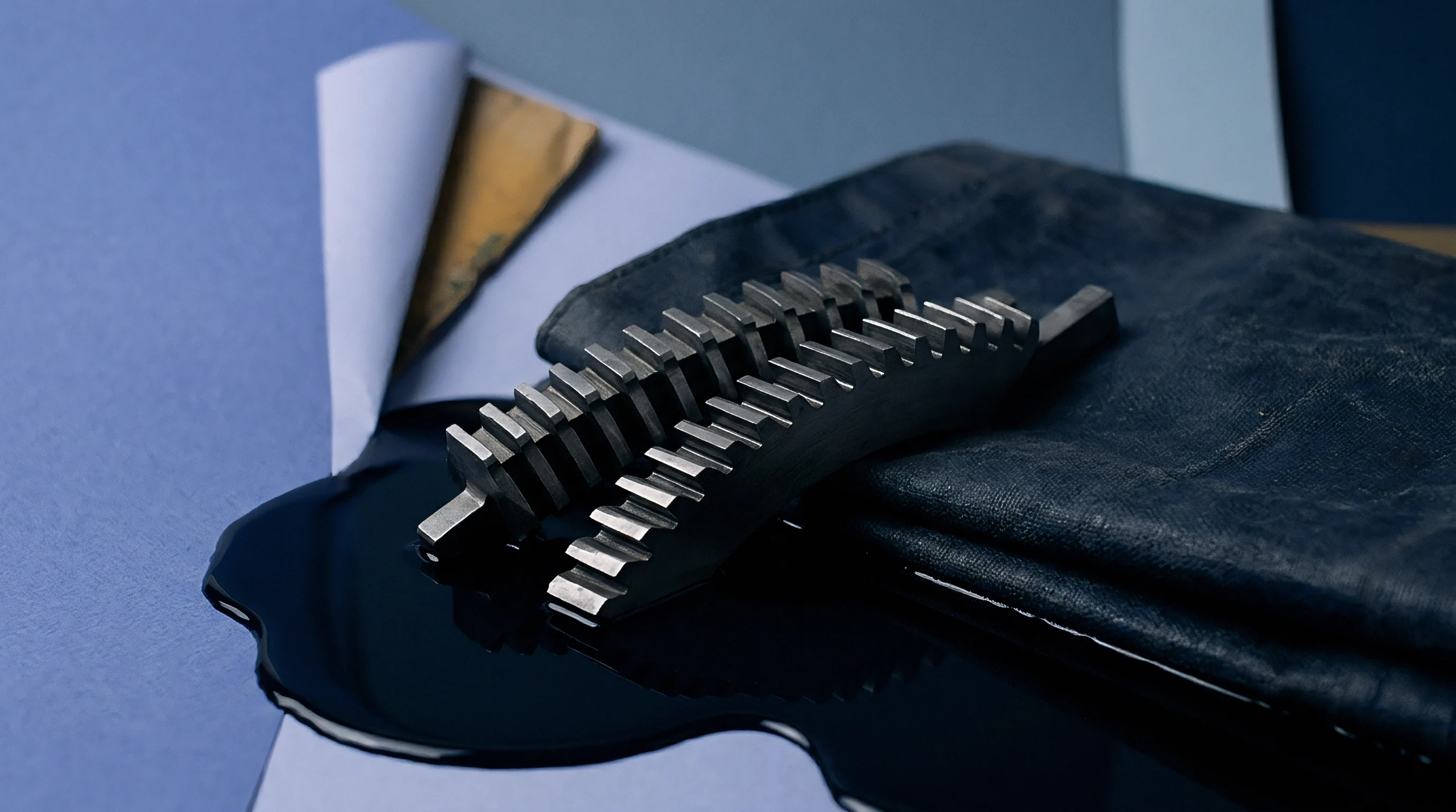
Structural Failure Modes under Dynamic Press Forces
High-velocity liquid flow across micro-engraved ceramic structures induces mechanical and chemical fatigue mechanisms that degrade volumetric delivery precision over time.
- Ceramic wall micro-fracturing under continuous impact from doctor blade contact pressure and hydraulic fluid hammer phenomena leads to cell wall collapse and volumetric expansion across high-wear roll bands.
- Thermal shock cracking resulting from rapid localized heat generation along doctor blade contact zones degrades the structural integrity of the plasma-sprayed chromium oxide layer, allowing moisture and acid corrosion to attack the underlying steel core.
- Insoluble pigment compaction occurring in cell bottom corners reduces effective volumetric capacity when high shear forces squeeze vehicle liquids out of the cell while compacting solid pigment particles into immobile cakes.
- Chemical leaching of ceramic binders driven by aggressive alkaline washing solutions or low-pH fountain additives weakens micro-engraved land structures, accelerating abrasive surface wear under doctor blade friction.
Where Does Hydrodynamic Lift Rupture Boundary Metering Compliance?
Hydrodynamic lift ruptures mechanical boundary compliance when fluid pressure generated within the convergent blade entry zone exceeds the pneumatic loading force of the chamber blade holder. As press velocity increases, the fluid wedge forces the doctor blade edge off the ceramic land area, creating a continuous liquid lubrication film between the blade steel and the ceramic roll. This hydroplaning state transforms the metering system from a positive displacement mechanical wipe into an unstable hydrodynamic film-splitting regime, resulting in sudden increases in wet coat weight, severe film weight variation across the web, and loss of print dot sharp definition.
| Cell Structure Type | Screen Count (cm⁻¹) | Target Volume (cm³/m²) | Depth-to-Opening Ratio (%) | Shear Rate at 400 m/min (s⁻¹) | Evacuation Efficiency (%) |
|---|---|---|---|---|---|
| Standard Hexagonal 60° | 360 | 4.2 | 28 | 3.8 x 10⁵ | 42 |
| Elongated Hexagonal 75° | 400 | 3.5 | 24 | 4.5 x 10⁵ | 51 |
| Tri-Helical 45° Channel | 200 | 8.0 | 18 | 2.1 x 10⁵ | 68 |
| Open Wave Continuous | 320 | 5.0 | 20 | 3.2 x 10⁵ | 62 |
When ceramic volumetric delivery drops or displays irregular wear patterns across press runs, fine cell screen counts are often held to blame for inherently degrading fluid flow, regardless of press speed or ink rheology tuning.
Viscosity
Liquid inks used in flexographic printing exhibit complex non-Newtonian rheology under operational shear rates. Bulk liquid viscosity measured at rest or under low shear on standard outflow cups does not reflect fluid resistance inside the doctor blade metering gap. Under shear rates exceeding 100,000 inverse seconds, liquid polymer solutions undergo severe mechanical orientation.
Polymer chains align parallel to the flow direction, causing rapid structural disentanglement and dramatic apparent viscosity reductions. This pseudoplastic shear-thinning behavior governs how ink flows into and out of anilox cells.
Measuring liquid resistance at 105 s-1 to 106 s-1 demands dynamic capillary viscometry or high-shear rotational rheometry. Standard outflow cups measure low-shear gravity flow at strain rates under 100 inverse seconds, providing zero actionable insight into how an ink behaves under doctor blade metering forces. Two inks displaying identical efflux times on a Zahn 2 cup can display radically different high-shear viscosity profiles, producing completely different wet coat weights on high-speed press runs.
High Shear Rate Viscosity Plateau Evaluation
Non-Newtonian fluid formulations follow dynamic rheological curves marked by distinct flow regions. At extremely low shear rates, fluids exhibit an upper Newtonian viscosity plateau (η0). As shear stress increases, the fluid enters a power-law shear-thinning regime where apparent viscosity declines rapidly.
At high shear rates approaching 106 s-1, fluid molecules reach maximum mechanical alignment, entering a lower infinite-shear viscosity plateau (ηinfty).
The numerical value of ηinfty dictates true metering resistance inside the doctor blade nip. Capillary rheometers fitted with 50-micrometer dies measure high shear rate viscosity for formulation testing. If an ink formulation maintains a high ηinfty value, hydrodynamic lift forces beneath the doctor blade increase significantly, promoting blade hydroplaning at high press speeds.
Conversely, if ηinfty drops too low, fluid internal cohesion breaks down entirely, leading to ink misting, splashing within the chamber, and erratic cell filling mechanics.

Thixotropic Recovery Timelines during Ink Transfer
Thixotropy describes time-dependent structural recovery following severe mechanical shearing. When liquid ink passes beneath the doctor blade, its polymer network is fully sheared and disentangled. Upon exiting the doctor blade contact zone, the fluid experiences an immediate drop in shear rate down to near-zero conditions within the cell cavity prior to plate cylinder contact.
The time required for the polymer network to reform its structural viscosity determines transfer behavior.
If structural viscosity recovery occurs too rapidly, within fractions of a millisecond, the ink stiffens inside the cell cavity before transferring to the flexographic plate surface, resulting in poor volumetric transfer rates and severe pinholing in solid print areas. If structural recovery is excessively slow, the fluid remains extremely thin during plate contact and substrate transfer, leading to severe dot gain, edge slurring, and ink pooling along printed graphic contours.
Inks with rapid thixotropic structural recovery require lower cell depth ratios to achieve uniform ink release at press speeds exceeding 400 meters per minute.
Polymer Chain Mechanics under Shear Stress
Ink formulation chemistries dictate molecular structural response under violent liquid strain fields. Water-based flexographic inks rely on acrylic resin solutions neutralized with volatile amines, extended with emulsion polymers. Under high shear forces, these branched synthetic polymer chains undergo reversible mechanical deformation, stretching along flow stream vectors.
Solvent-based formulations utilizing nitrocellulose or polyamide resins feature shorter, more rigid polymer backbones that align rapidly with minimal elastic strain energy storage.
UV-curable inks present unique non-Newtonian challenges due to their high concentration of oligomers, reactive monomer diluents, and photoinitiators, containing zero volatile solvents. Because UV formulations lack evaporating carrier liquids, their initial bulk viscosity is naturally much higher, often between 500 and 1500 mPa·s at rest. Under high shear metering rates, UV oligomer chains generate intense viscous resistance, creating extreme hydrodynamic lift forces that demand double the mechanical blade loading pressure required for solvent-based inks.
| Ink Chemistry System | Zero-Shear Viscosity η₀ (mPa·s) | Infinite-Shear Viscosity η∞ (mPa·s) | Carreau Relaxation Time λ (s) | Thixotropic Index (10:1 Shear Ratio) | Misting Threshold Velocity (m/min) |
|---|---|---|---|---|---|
| Water-Based Acrylic | 350 | 18 | 0.012 | 2.8 | 450 |
| Solvent Nitrocellulose | 120 | 12 | 0.002 | 1.4 | 650 |
| UV-Curable Acrylate | 1200 | 45 | 0.045 | 4.2 | 320 |
| Water-Based Polyurethane | 480 | 22 | 0.018 | 3.1 | 400 |
Higher binder molecular weight increases ink vehicle cohesion, reducing misting at high press speeds regardless of solvent evaporation rate.

Blade
Doctor blade contact mechanics form the physical boundary governing fluid metering across engraved roll surfaces. In enclosed chamber systems, two opposing blades contact the ceramic roll surface under pneumatic load. The lower blade acts as a fluid seal to prevent ink leakage, while the upper blade serves as the reverse-angle metering blade, shearing excess ink away from ceramic land areas.
The mechanical interaction between the flexible steel or composite blade tip and the rigid ceramic roll face operates under high contact friction, hydraulic liquid pressure, and dynamic deflection forces.
Standard reverse-angle metering setups align the doctor blade at a target contact angle between 28 degrees and 35 degrees relative to the tangent line at the contact point. If the contact angle drops below 25 degrees, the blade presents a wide contact footprint that acts as a hydroplaning ski, elevating the blade off the ceramic lands. If the contact angle exceeds 38 degrees, the blade edge acts as a mechanical scraper, causing rapid tip chipping, micro-spalling of the ceramic land walls, and aggressive blade tip wear.
Contact Mechanics and Tip Deflection Angles
Blade tip profile geometry establishes the contact stress distribution across the metering zone. Three primary tip profiles dominate industrial applications: standard straight-cut tips, bevel-cut tips, and lamella reduced-thickness tips. Lamella blades feature a thin step-down section along the working edge, typically 50 to 100 micrometers thick, maintaining a constant contact area throughout the operational lifespan of the blade.
Contact pressure distribution across the lamella edge remains uniform even as mechanical loading force varies. Lamella tip blades maintain uniform metering contact under lower total chamber pressure. Straight-cut and bevel-cut blades experience expanding contact area width as the steel tip wears down under ceramic friction.
As contact width expands, nominal contact pressure drops proportionally, allowing hydrodynamic fluid lift to force the blade edge upward, causing gradual wet coat weight drift across continuous press runs.

Hydrodynamic Lift Calculations for Metering Chambers
Fluid moving inside the enclosed chamber generates dynamic hydraulic pressure along the entry wedge of the doctor blade. This hydrodynamic lift force can be approximated using simplified Reynolds lubrication equations for narrow sliding gaps:
F_h = (6 μ U L²) / h²
Where F_h represents the total upward hydrodynamic lift force per unit width, μ represents the local ink dynamic viscosity at high shear rate (η_∞), U represents the roll surface line velocity, L represents the contact length of the fluid wedge, and h represents the minimum fluid film gap height between blade tip and ceramic land area.
The mathematical relationship demonstrates that hydrodynamic lift forces scale linearly with line velocity U and liquid viscosity μ, but increase quadratically with wedge contact length L and inversely with the square of gap height h. When line speed doubles, mechanical pneumatic blade loading force must increase proportionally to prevent hydrodynamic lift from forcing the gap height h to expand, which would result in uncontrolled film laydown increases.
Non-compliance with ISO 12647 density variation tolerances occurs when chamber doctor blade deflection exceeds 12 micrometers under dynamic fluid loading.
Mechanical Setup Protocol for Chamber Alignment
Achieving stable mechanical metering performance requires methodical alignment procedures during press prep and chamber installation.
- Inspect chamber sealing end-seals for dimensional swelling, chemical hardening, or mechanical wear that prevents uniform chamber seating against the anilox roll ends.
- Clean doctor blade clamping surfaces thoroughly, removing dried resin, ink scale, and micro-debris that create localized clamping pressure variations along the blade length.
- Mount high-precision blue steel or ceramic-coated doctor blades into the clamping bar, utilizing a torque wrench to tighten clamping bolts sequentially from the center outward to prevent blade structural buckling.
- Verify blade tip straightness using a precision mechanical straightedge, ensuring total tip deviation stays below 0.05 millimeters per meter of blade length.
- Position the chamber assembly parallel to the anilox roll axis, checking that both upper and lower blade tips contact the ceramic surface simultaneously across the entire face width.
- Apply initial pneumatic loading pressure incrementally up to the minimum sealing threshold, avoiding excessive mechanical over-tightening that bends blade edges into wider contact angles.
- Circulate fluid through the chamber system, monitoring return line flow rates and internal chamber pressure gauges to verify hydraulic balance before starting roll rotation.
- Accelerate roll rotation smoothly to target production speed, adjusting pneumatic load in small steps only if visual inspection reveals ink weeping or hydroplaning streaks.
| Blade Material Composition | Tensile Strength (MPa) | Elastic Modulus (GPa) | Tip Profile Type | Nominal Contact Width (µm) | Hydrodynamic Lift Resistance Index |
|---|---|---|---|---|---|
| Standard Carbon Steel | 2000 | 210 | Straight Cut | 150 – 300 | Low |
| Micro-Alloy Swedish Steel | 2200 | 215 | Lamella (100 µm) | 100 (Constant) | High |
| Ceramic Coated Steel | 2100 | 210 | Bevel 20° | 80 – 200 | Moderate |
| Ultra-High Polymer Composite | 180 | 9.5 | Rounded Edge | 500 – 800 | Very Low |
Doctor blade steel specifications referencing ISO 12647 tolerances require tip width straightness within 0.02 millimeters per meter to eliminate localized film weight streaking across wide-web presses.

Cavitation
Micro-cavitation within engraved cells is a main driver of inconsistent fluid discharge and micro-foam defects in high-speed flexographic printing. As individual engraved cells rotate past the doctor blade metering edge, liquid trapped inside experiences violent localized pressure shifts. Inside the chamber, ink enters the cell under positive hydraulic delivery pressure.
As the cell passes beneath the blade contact land area and emerges downstream, sudden mechanical boundary release triggers a sharp drop in pressure within the microscopic cell cavity.
The localized pressure drop at the trailing cell wall can fall below the vapor pressure of the liquid vehicle, causing micro-cavitation bubbles to nucleate within microseconds. As the roll rotates toward the plate cylinder nip, these micro-bubbles expand, coalesce, and violently collapse according to Rayleigh-Plesset bubble dynamics. These collapses generate micro-jets that disrupt the liquid meniscus, causing splattering along cell edges and leaving partial air voids within the cavity that reduce total transferred ink weight.

Pressure Drops at Trailing Cell Walls
Cell trailing edge geometry directly influences local pressure drop magnitudes during cell emergence from the doctor blade edge. Flat, steep-walled trailing cell boundaries create sudden flow detachment zones where fluid velocity vectors cannot smoothly follow the cell wall profile. Boundary layer breakdown occurs quickly.
The resulting pressure drop creates a localized vacuum pocket along the rear vertical wall of the cavity. Fluid flow simulations indicate that shallow trailing wall angles, such as those found in elongated 75-degree hexagonal cells or continuous open-wave channels, smooth the pressure gradient transition. Smooth transitions prevent localized static pressure from falling below liquid vapor pressure thresholds, suppressing micro-cavitation bubble formation during high-speed rotation.
Air Bubble Nucleation and Boundary Layer Trapping
Continuous circulation of liquid ink through chamber delivery pumps introduces dissolved air into the fluid matrix. High velocity mechanical shearing inside the chamber breaks entrained air into microscopic air bubbles measuring between 1 and 10 micrometers in diameter. These micro-bubbles act as pre-existing nucleation sites for micro-cavitation events when fluid passes through the pressure drop zone beneath the doctor blade.
Sub-micron air bubbles trapped inside cell bottom corners resist fluid displacement during ink chamber filling cycles. The surface tension forces of the liquid vehicle, combined with low substrate wetting characteristics, seal the air pocket in place at the base of the cell. Occupying cell volume with trapped air pockets reduces functional liquid capacity, altering the volumetric delivery calibration of the anilox roll during live production.
Surfactant Equilibrium Criteria
Formulators utilize specialized surfactant systems to control static and dynamic surface tension in flexographic inks, especially water-based formulations operating at dynamic liquid-air surface ages under 10 milliseconds.
- Dynamic surface tension reduction balance achieved by blending fast-acting acetylenic diol surfactants lowers dynamic surface tension to below 30 mN/m within 5 milliseconds of surface generation, promoting cell wall wetting and suppressing air trapping.
- Defoamer molecule compatibility thresholds managed to prevent insoluble hydrophobic particle aggregation that fouls ceramic cell bottoms while maintaining anti-foam activity within high-shear chamber agitation zones.
- Hydrophilic-lipophilic balance optimization for ink resin solubilization stabilizes ink vehicle viscosity under micro-cavitation pressure spikes, preventing shear-induced resin precipitation along cell rims.
- Substrate surface wetting energy differential calibrated to ensure the liquid ink surface energy remains at least 10 mN/m below the solid surface energy of the printing plate polymer for rapid volumetric transfer.
What fundamental fluid mechanics limit prevents complete elimination of micro-cavitation events when press speed exceeds 800 meters per minute?
Yield
The operational and economic consequences of anilox cell metering dynamics converge directly on dry ink coat weight stability, graphic print density control, and net converting substrate yield. Flexographic converters buy substrate reels by weight or total surface area, but sell printed packaging based on strict color tolerance specifications defined by CIELAB delta E color thresholds. Uncontrolled volumetric delivery drift caused by doctor blade hydroplaning, high shear ink thinning, or cell cavitation leads directly to off-shade production, web rejection, and wasted substrate tonnage.
Maintaining ink laydown stability across press speed acceleration curves represents a primary converting headroom metric. On modern wide-web packaging presses running coated paperboard or virgin solid bleached sulfate liners, line speeds vary from 50 meters per minute during setup up to 500 meters per minute during continuous production. If ink shear-thinning and doctor blade hydrodynamic lift forces are not precisely balanced, the optical density of printed solid graphics shifts continuously across press speed adjustments, producing out-of-spec material during press acceleration and deceleration cycles.
Film Thickness Control across Press Velocity Curves
Wet ink film thickness (hwet) delivered to the substrate surface depends on the product of anilox cell volumetric capacity (Vcell), total transfer efficiency factor (Etrans), and blade metering compliance factor (Cmeter):
h_wet = V_cell E_trans C_meter
In an ideal mechanical state, the metering compliance factor Cmeter remains precisely equal to 1.00 across all line speeds, delivering constant wet film thickness. In high shear press environments, hydroplaning increases Cmeter above 1.00, increasing laydown weight, while micro-cavitation and cell trapping drop Etrans below nominal baseline values.
Increasing press speed from 200 to 500 meters per minute drops ink film thickness by 0.22 grams per square meter on high-speed converting lines. This variation destabilizes color matching models. To compensate, press operators frequently adjust ink viscosity on the fly by adding water, solvents, or amines, further destabilizing ink vehicle non-Newtonian rheology and accelerating mechanical blade wear.
Substrate Intake Dynamics and Wet Laydown Metrics
The physical properties of the target packaging substrate govern how liquid ink films settle, penetrate, and dry following transfer from the flexographic plate cylinder. Coated folding carton board grades featuring high Bendtsen smoothness and controlled Cobb sizing accept liquid ink films cleanly, requiring minimal wet laydown thickness to achieve maximum optical ink density. Highly porous unbleached kraft liners absorb liquid ink vehicle rapidly into the internal fiber matrix, demanding higher volumetric laydown to maintain surface color saturation.
When high shear metering instability generates wet film thickness variations on porous kraft substrates, liquid penetration depth fluctuates across the web face width. Fluctuation creates structural mottle, pinholing, and erratic surface gloss levels. On non-porous flexible packaging films like oriented polypropylene or polyethylene terephthalate, wet film thickness variations produce ink drying rate differentials within hot-air dryer tunnels, resulting in residual solvent retention, web blocking on re-wound rolls, and severe odor complaints from end-use food packagers.

Economic Impact of Volumetric Metering Drift
Volumetric metering drift impacts converting financial performance through increased ink consumption, substrate waste generation, and press downtime required for doctor blade replacement and anilox roll deep cleaning. Ink vehicle costs represent a significant percentage of total variable converting costs in flexible packaging and folding carton plants. Delivering an unnecessary extra 0.3 grams per square meter of wet ink film weight across a high-volume job running 500,000 square meters of substrate consumes hundreds of kilograms of excess ink inventory without providing graphic benefit.
Managing the hydrodynamic, mechanical, and rheological variables within the flexographic anilox metering zone transforms high-speed printing from an unstable trial-and-error process into a predictable, engineered manufacturing system. Matching doctor blade deflection dynamics, cell structural geometry, and high-shear ink rheology enables flexographic packaging converters to maximize press velocity without sacrificing coat weight precision, color compliance, or substrate yield integrity.