Optical Displacement Calibration for Bleached Paperboard Crease Inspection
Optical displacement calibration on bleached board demands non-penetrating ceramic standards to eliminate 25-micrometer errors from pulp scatter.


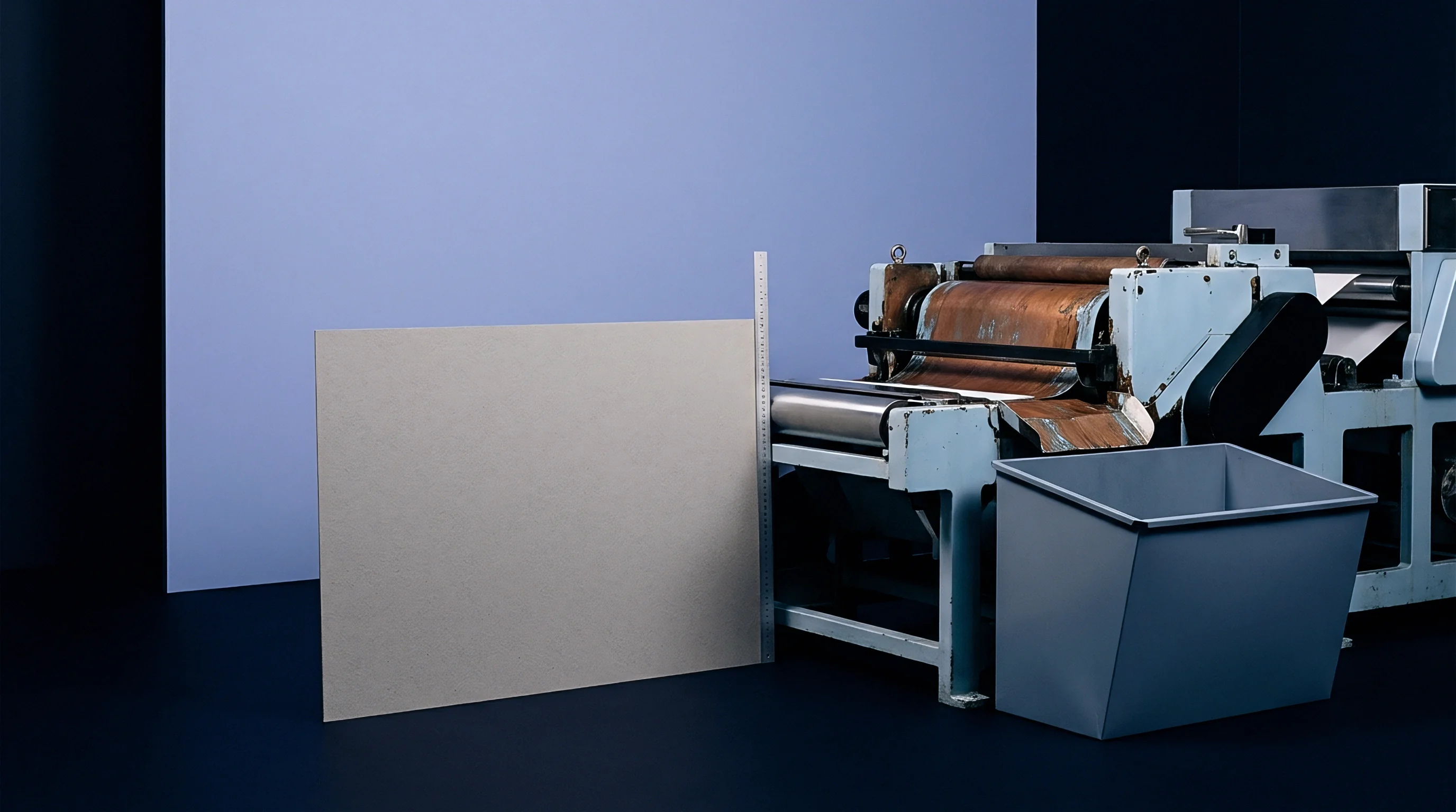
Probe
Positioning a chromatic confocal optical displacement head four millimeters above a running web of 350 gsm solid bleached sulphate board exposes the mechanical reality of converting inspection. The focal spot scans across. Surface elevation varies across fractions of a millimeter as the board travels over the anvil cylinder.
A crease line pressed into bleached chemical pulp is an intentional disruption of the fibrous matrix, bounded by two raised shoulders and a central depression. Capturing that three-dimensional relief at web speeds exceeding three hundred meters per minute demands sub-micron vertical resolution combined with lateral spot dimensions smaller than twenty micrometers.
Optical displacement sensors deployed on folding carton lines operate under tight physical constraints. Laser triangulation units project a focused semiconductor diode beam onto the bleached board surface, imaging the diffuse reflection onto a linear complementary metal-oxide-semiconductor array at an oblique angle. Chromatic confocal pens use hyperchromatic lens arrangements to split polychromatic white light along the optical axis, mapping the reflected wavelength to distance without triangulation parallax.
The selection between these two measurement architectures governs the susceptibility of the inspection system to local surface variations.
Calibrated at 23 degrees Celsius and 50 percent relative humidity, a chromatic confocal head maintains an axial measuring range of 1.2 millimeters with a root-mean-square displacement resolution of 0.08 micrometers.

Sensor Geometry and Spot Dimensions
Triangulation systems project an elliptical footprint across the score zone. When the projected axis aligns parallel to the carton score, the sensor integrates elevation across the width of the crease groove, smoothing the sharp transitional inflection at the shoulder edge. Aligning the triangulation plane perpendicular to the crease direction resolves the shoulder slopes cleanly, yet risks shadowing errors along the trailing flank of deep male beads.
Chromatic confocal pens project circular spots down to twelve micrometers in diameter. Their normal incidence avoids mechanical occlusion within the creasing depression.
Diffuse scatter replaces specular reflection. Solid bleached board presents a porous network of delignified softwood and hardwood kraft fibers, coated with calcium carbonate and kaolin clay layers bound by styrene-butadiene latex. Laser light hitting this unprinted white surface does not rebound from an infinitely thin plane.
The incident beam undergoes volume scattering, penetrating the top mineral coating and entering the bleached fiber matrix before emerging. This lateral subsurface migration inflates the apparent optical spot size, degrading the true lateral resolution of triangulation receivers.

Triangulation versus Confocal Chromatic Profiles
Each optical approach responds differently to board flutter and web vibration. Mechanical vibration shifts the crease profile within the measuring field, introducing dynamic displacement artifacts that register as false variations in bead height.
- Chromatic confocal sensors isolate wavelength peaks independently of receiver tilt, delivering repeatable altitude values across steep crease shoulders up to forty-five degrees of inclination.
- Laser triangulation arrays offer acquisition rates up to fifty kilohertz, capturing high-density cross-web profiles at maximum folder-gluer velocities.
- Specular triangulation heads produce intense receiver saturation on high-gloss cast-coated bleached boards, requiring real-time closed-loop laser exposure control to prevent spatial clipping.
- Telecentric confocal lenses preserve perpendicular ray geometry across the field, eliminating the trapezoidal image distortion that alters crease width calculations on thicker packaging substrates.
When displacement sensors operate outside their calibrated axial sweet spot, non-linearities in the optical train corrupt the calculated crease depth. The folder-gluer operator then adjusts the scoring collar pressures based on distorted dimensional data, crushing the board core and precipitating premature carton panel roll-over on automated high-speed cartoning lines.

Target
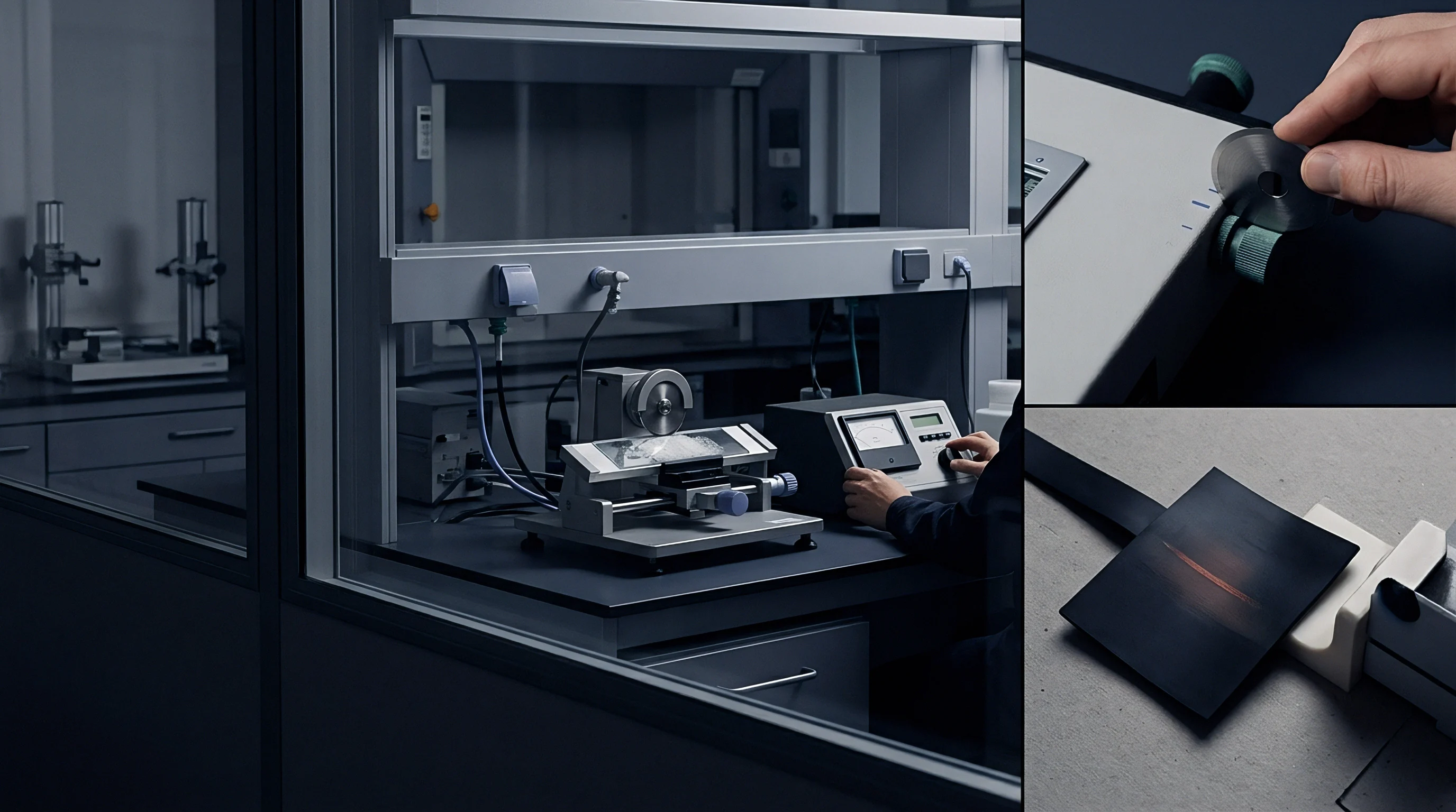
Direct verification of an optical gauge requires stable artifacts that decouple the sensor physics from the instabilities of cellulose. Calipers drift under ambient swings. Using a production paperboard sample to calibrate an optical displacement system introduces systematic errors because paperboard thickness expands and contracts with atmospheric moisture.
Standardizing an inline or benchtop optical crease measurement device relies on certified physical artifacts manufactured from materials with near-zero thermal expansion and invariant optical scatter properties.
Matte ceramic reference specimens provide the baseline for displacement verification. Highly polished glass or tungsten carbide gauge blocks exhibit strong specular reflection that overwhelms diffuse triangulation sensors or produces phase cancellations in optical sensors calibrated for matte media. Sintered aluminum oxide ceramics with a calibrated diffuse reflectance between eighty-five and ninety percent replicate the gross optical reflectivity of solid bleached sulphate board without introducing the subsurface light penetration characteristic of cellulose fibers.
Contractual acceptance criteria under ISO 12647-7 require optical verification standards to hold certified dimensional uncertainty within plus or minus 0.5 micrometers traceable to national metrology institutes.

Physical Calibration Masters and Matte Ceramic Artifacts
Step-height artifacts machined from ceramic substrates feature precision-milled grooves matching standard die-cutting rule dimensions. Rule widths for folding cartons commonly span from 0.71 millimeters (two-point rule) to 1.42 millimeters (four-point rule), with crease channel depths milled from 0.40 to 0.80 millimeters. An ideal calibration target integrates a stepped series of calibrated grooves: flat reference plane, 200-micrometer step, 400-micrometer groove, and 800-micrometer trough, all lapped to a certified surface roughness Ra between 0.35 and 0.45 micrometers.
The gauge records sixty points. This roughness value matches the micro-topography of triple-coated bleached paperboard without creating localized micro-shadows that split the reflected optical peak. Calibration routines run the optical sensor across these precision steps to construct the transfer function relating sensor output voltage or digital pixel index to physical z-axis displacement.
| Substrate or Master | Specular Gloss 60 Deg | Surface Roughness Ra | Thermal Expansion Coeff | Optical Penetration |
|---|---|---|---|---|
| Sintered Alumina Master | 3.2 percent | 0.40 micrometers | 8.1 x 10^-6 / K | Zero |
| Diffusing Opal Glass Master | 4.1 percent | 0.05 micrometers | 7.6 x 10^-6 / K | 12 to 18 micrometers |
| Polished Silicon Wafer Master | 98.5 percent | 0.01 micrometers | 2.6 x 10^-6 / K | Zero |
| SBS Board Coated 280 gsm | 38.0 percent | 0.95 micrometers | Cellulose expansion | 35 to 65 micrometers |
| SBS Board Uncoated 280 gsm | 6.5 percent | 3.80 micrometers | Cellulose expansion | 80 to 140 micrometers |

Step Height Verification and Optical Zeroing
Establishing the reference baseline on a moving converting machine demands a two-tier zeroing sequence. Structural vibrations in the converting frame transmit high-frequency displacements through the sensor bracketry. A static zero point derived on an anvil roller at standstill does not match the dynamic center line of a web tensioned to two hundred newtons per meter.
- Mount the certified ceramic step master into the off-line gauge fixture under standard laboratory conditioning of 23 degrees Celsius and 50 percent relative humidity according to ISO 187.
- Execute an axial traverse of the optical displacement sensor across the reference plinth, capturing one thousand discrete elevation points per millimeter of travel.
- Compute the baseline plane through a least-squares linear regression of the ungrooved master shoulders, rejecting outliers deviating beyond three standard deviations.
- Offset the zero datum to the computed baseline and scale the z-axis voltage gain until the measured groove depths correspond with the certified master calibration certificate.
Where purchasing specifications cite ISO 13849 safety and machine reliability standards, the calibration certificate must stipulate the exact optical wavelength and sensor exposure frequency utilized during master verification, precluding the mill from disputing out-of-spec score dimensions when alternative optical heads are fitted to downstream folder-gluers.


Ridge
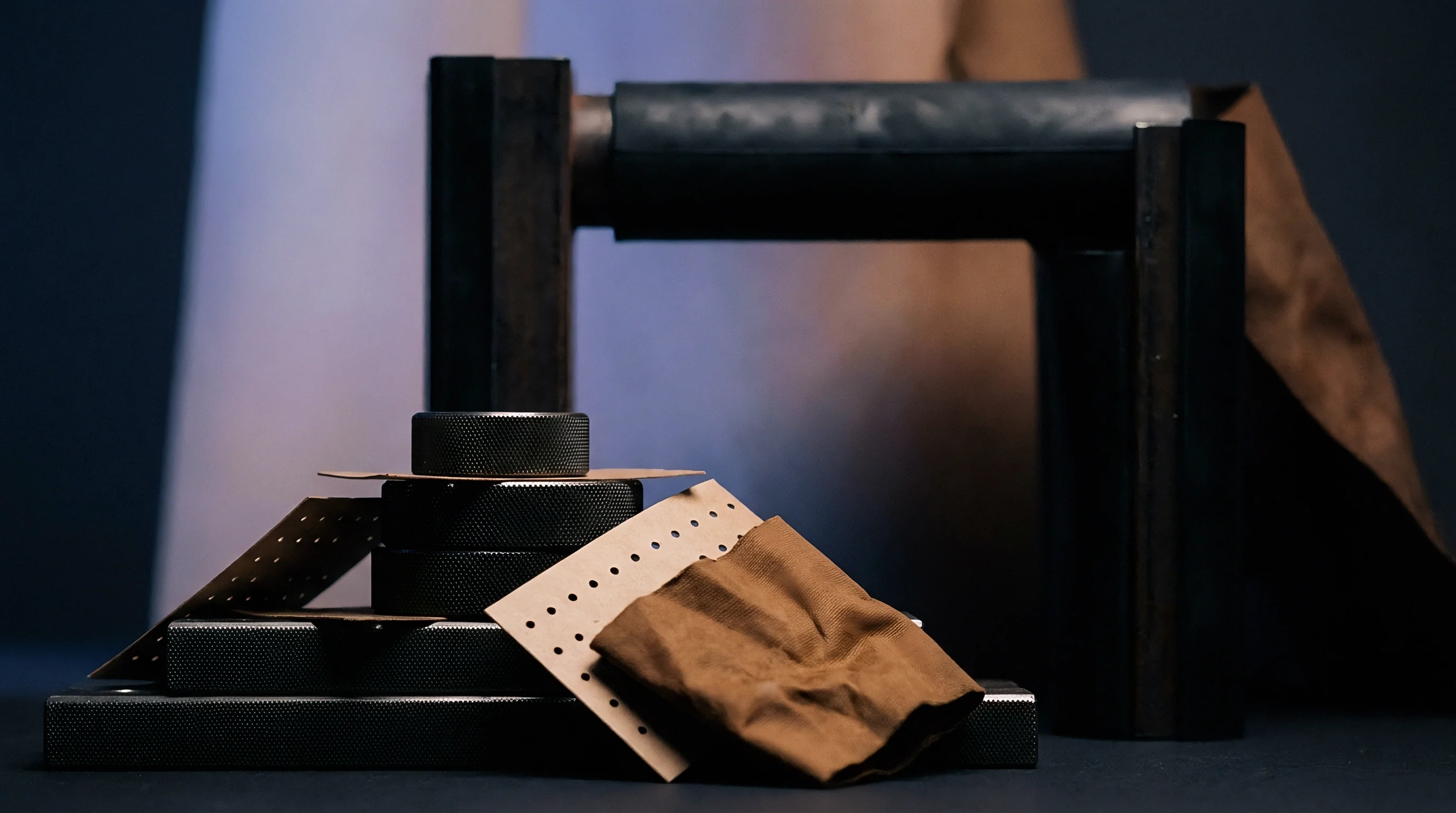
Creasing paperboard is an act of controlled internal shearing rather than pure mechanical embossing. Plates wear down over time. When a steel rule presses bleached paperboard into an underlying counter-matrix groove, the sheet experiences intense localized transverse shear and out-of-plane compression.
The furnish in solid bleached board consists of long softwood fibers in the interior to build tensile strength, combined with short hardwood fibers on the surfaces for flatness and printability. As the scoring rule strikes the top side, this multi-ply structure delaminates internally.
Delamination controls the internal hinge. A properly calibrated optical profile reveals this internal mechanical disruption through outer surface geometry. The underside of the board forms a defined bead that seats into the matrix channel, while the top surface forms an indented trough bounded by subtle raised shoulders.
If the board retains too much structural integrity without delaminating, the bead fails to form and surface fibers rupture. If the board delaminates excessively, the crease loses all bending stiffness, causing carton flaps to wander during packing line closing operations.
A crease that preserves hinge integrity presents a bead height equal to sixty-five percent of the uncreased board caliper while maintaining an unbroken top coating layer.
Crease Bead Width and Delamination Bulge
Measuring the cross-sectional geometry of the crease demands accurate boundary segmentation. The crease bead does not present vertical walls. It forms a smooth, bell-shaped displacement curve whose shoulders merge gradually into the uncompressed carton panel.
Optical displacement inspection systems evaluate the crease profile through three primary parameters: total groove depth on the rule side, bead height on the matrix side, and the inflection width measured across the bead shoulder bases.
Shear splits the internal plies. The width of the bead must clear the edges of the counter-matrix during folding. When the female creasing matrix is sized too narrow, the sides of the male bead are pinched, generating asymmetric shearing forces that fracture the outer bleached liners.
When the matrix channel is too wide, the board sags into the gap without undergoing shear, creating a wide, shallow bead with low bending resistance and undefined hinge coordinates.
| Board Caliper (microns) | Grammage (gsm) | Rule Thickness (pt) | Matrix Channel Width (mm) | Nominal Bead Height (microns) |
|---|---|---|---|---|
| 300 | 215 | 1.5 pt (0.53 mm) | 1.0 mm | 195 |
| 400 | 275 | 2.0 pt (0.71 mm) | 1.3 mm | 260 |
| 500 | 340 | 2.0 pt (0.71 mm) | 1.5 mm | 325 |
| 600 | 405 | 3.0 pt (1.05 mm) | 1.9 mm | 390 |
| 700 | 460 | 3.0 pt (1.05 mm) | 2.2 mm | 455 |

Symmetry Ratios across the Score Line
Balanced folding depends on bilateral symmetry. Asymmetric crease profiles arise when the die-cutting rule is misaligned relative to the matrix channel, or when the sheet shifts dynamically during the platen impression stroke. An optical sensor scanning across the bead identifies the centroid of the indentation and compares the left and right slope gradients.
- Shoulder slope mismatch indicates lateral deflection of the creasing rule under load, shifting the folding axis away from the intended package panel dimension.
- Shoulder height differential signals uneven platen pressure across the carton blank, creating localized areas prone to diagonal twisting during the initial ninety-degree fold.
- Bead crest flatting appears when the matrix depth is insufficient, bottoming out the board bead against the steel plate and causing fiber crushing.
- Secondary micro-creasing occurs alongside the primary score when worn matrix channels allow lateral board slippage under the rule strike.
Scores pop open at speed. When asymmetry exceeds twelve percent of total bead width, the folding torque on the folder-gluer develops an uneven force couple. The carton panel hinges not along its center line, but along the weaker, over-sheared shoulder edge.
The carton glues out of square, skewing manufacturer seals and jamming cartoner loading pushers.
A stable rule strikes the channel center without forcing the board against the sidewalls.


Translucency
Photons migrate through fiber networks. Solid bleached sulphate boards consist entirely of bleached virgin chemical pulps, characterized by high brightness values ranging from eighty-four to ninety-four percent ISO under ISO 2470. Bleaching removes light-absorbing lignin, leaving a carbohydrate network of cellulose and hemicellulose that exhibits high optical scattering and very low optical absorption in the visible spectrum.
This chemical purity creates a measurement hazard: incident light from an optical sensor does not bounce cleanly off the outermost surface boundary, but enters the translucent sheet body.
Laser triangulation sensors calculate distance by detecting the peak of the light distribution focused on their detector arrays. When the beam penetrates the board, light scatters sideways and backwards from interior fiber-air interfaces before reaching the detector lens. The detector receives a diffuse, expanded blob rather than a sharp spot.
Because the internal scattering volume is non-uniform, the centroid of this distribution shifts relative to the actual mechanical top edge of the board, introducing an optical penetration offset that corrupts true displacement readings.
Uncalibrated laser triangulation over bleached virgin paperboard records an apparent displacement 25 to 55 micrometers deeper than the true mechanical surface established by stylus profilometry.

How Does Penetration Depth Skew Peak Detection?
Subsurface photon migration varies with local sheet density. In the uncreased board panel, the fiber network retains its manufactured density, typically around 0.75 to 0.85 grams per cubic centimeter for bleached sulphate grades. Inside the crease groove, the die rule compresses the board, driving the local density above 1.15 grams per cubic centimeter.
This severe mechanical compaction collapses fiber lumens and eliminates internal air voids, altering the local refractive index environment.
Titanium dioxide scatters incident rays. With fewer light-scattering internal voids in the compressed crease base, the optical beam penetrates deeper into the board core before backscattering. Across the uncompressed crease shoulders, the board remains porous, causing shallower penetration.
Consequently, the optical sensor measures an exaggerated groove depth: the recorded optical profile reports both the physical depression and the localized change in optical scattering length. Stylus contact profilometers confirm this error, showing that optical displacement sensors systematically overestimate crease groove depth on bleached stocks by fifteen to thirty percent if uncorrected.

Pigment Coatings and Optical Brightener Interference
Surface treatments on bleached board compound the displacement calibration offset. Packaging boards usually carry double or triple mineral coatings consisting of ground calcium carbonate and fine kaolin clay. Clay platelets align parallel to the board surface, creating a barrier that reduces light penetration.
Calcium carbonate particles, conversely, act as isotropic scatterers that diffuse the beam immediately below the surface.
Optical brightening agents added to the furnish or coating absorb ultraviolet radiation between 340 and 380 nanometers and re-emit fluorescence in the blue visible spectrum between 420 and 470 nanometers. When triangulation systems utilize blue laser sources operating near 405 nanometers to minimize spot size, the beam excites the optical brighteners. The sensor array then captures both the reflected laser photons and the isotropic fluorescent glow emitted from deep within the sheet plies.
The fluorescent emission carries no directional phase information, washing out the reflected signal-to-noise ratio and distorting peak detection algorithms.
The board manufacturer insists that variations in crease depth readings across different board batches stem entirely from improper optical gauge zeroing on the press floor, rather than shifts in the mill coating formulation or pulp freeness.

Margin
Line stoppages destroy run margins. The economic impact of crease inspection rests on preventing jams in high-speed packaging machinery. Modern packaging lines for pharmaceuticals, foods, and cosmetics erect, fill, and seal folding cartons at speeds between four hundred and one thousand units per minute.
At these speeds, a carton flap that resists folding by five millinewton-meters above specification will trip the line insertion arm, initiating an automated line purge. Running forty-tonne board lots through converting without robust displacement calibration turns high-yield carton stock into press waste.
Consider a typical packaging converter running a 40-tonne order of 320 gsm solid bleached sulphate board, producing approximately 450,000 pharmaceutical cartons. The uncreased board possesses an initial machine-direction bending resistance of 310 millinewtons measured across a 50-millimeter sample width at a 15-degree bend angle according to ISO 2493-1. Correctly creased cartons require this bending resistance to drop to eighty millinewtons along the primary score line, yielding a crease stiffness ratio of approximately twenty-six percent.
Every ten-micrometer discrepancy in measured crease depth shifts the resulting carton fold bending moment by four to seven percent on 300 to 350 gsm bleached boards.

Which Tolerance Envelopes Prevent Folding Failures?
If the optical displacement sensor overestimates groove depth by twenty-five micrometers due to optical penetration errors, the press operator decreases the scoring counter-pressure to avoid tearing the sheet. The actual mechanical crease depth achieved is twenty-five micrometers shallower than intended. Instead of the targeted eighty millinewtons of bending resistance, the score retains a stiffness of one hundred and twenty-five millinewtons.
Cartons jam in downstream rails. This excess stiffness causes the carton side panels to bow outward during high-speed squaring, increasing the carton profile width by 1.2 millimeters. When the defective blanks enter the downstream automated cartoning machine, the carton fails to open completely within the eight-millisecond mechanical window provided by the rotary pick-and-place mechanism.
| Calibration Error Offset | Actual Crease Depth | Fold Resistance (ISO 2493) | Cartoner Jam Rate | Financial Loss on Run |
|---|---|---|---|---|
| Zero (Calibrated) | 210 micrometers | 82 mN | 0.02 percent | Base Run Cost |
| +10 micrometers (Deep) | 200 micrometers | 96 mN | 0.15 percent | 1,420 USD |
| +25 micrometers (Deep) | 185 micrometers | 125 mN | 2.40 percent | 18,900 USD |
| +40 micrometers (Deep) | 170 micrometers | 168 mN | 11.80 percent | 94,500 USD |
| -25 micrometers (Shallow) | 235 micrometers | Fiber cracking | 8.50 percent | 76,200 USD |

Commercial Impact on Packaging Line Speeds
A cartoner jam rate of 2.4 percent stops the line twenty-four times per hour. Tooling gaps compound web defects. The economic damage extends far beyond the raw scrap value of the paperboard.
In an automated filling plant operating at a conversion line charge of 650 USD per hour, recurring micro-stoppages degrade overall equipment effectiveness from a budgeted eighty-five percent down to fifty-two percent. Press operators discard flawed sheets.
The reverse failure mode carries equal financial exposure. When an optical calibration error reads the crease as shallower than reality, the die-cutting operator increases rule penetration. The steel scoring edge cuts into the top chemical pulp plies, rupturing the kaolin coating and breaking surface fibers.
While this reduces fold resistance, the broken outer fibers fissure when folded one hundred and eighty degrees during carton pre-breaking, displaying unsightly white cracks along printed dark carton edges. Brand owners reject entire shipments for cosmetic cracking, leaving the converter to absorb paperboard cost, printing expenses, and freight claims.
Whether inline optical displacement sensors can successfully decouple structural fiber penetration from mechanical surface elevation under varying web moisture contents on the converting floor remains a subject of active development across the packaging industry.