Compensating Tooling Growth and Counterforce Creep in High Speed Converting
Tooling growth and counterforce creep offset each other through chilled oil temperature control and hydraulic bearer adjustment.

Heat
Rotary die cutting cylinders operating at web velocities exceeding 250 meters per minute generate internal thermal energy through continuous mechanical action. Kinetic energy converts to energy losses across the bearing journals, ring contact zones, and shear interfaces where steel blades penetrate paperboard stock. High-speed operation elevates tool body temperatures significantly above ambient room levels.
This thermal shift causes physical mass enlargement that alters calibrated knife clearances.
Thermal Expansion Dynamics in Rotary Cylinders
Solid tool bodies machined from high-carbon alloy steels expand predictably when exposed to continuous friction. Steel expands uniformly along three dimensional axes relative to its coefficient of thermal expansion. Heat causes steel expansion.
A cylinder with a nominal body diameter of 250 mm experiences outward linear growth along its radius. Operating temperatures on long production runs routinely climb 15 to 25 Kelvin above setup conditions. Uncontrolled radial swelling reduces the clearance gap between the cutting blade tip and the counter cylinder.
Tool clearance collapses quickly. Standard kiss-cutting applications for self-adhesive label stock maintain an operating clearance between 12 and 18 microns. A thermal rise of 18 Kelvin on a 250 mm D2 steel cylinder increases the body radius by approximately 24.3 microns.
This radial growth completely consumes the nominal clearance gap. The knife edge strikes the underlying hardened cylinder with destructive impact force. Edge blunting occurs within thousands of revolutions, dulling the cutting rule and generating excessive debris.
| Alloy Grade | CTE (10^-6 / K) | Hardness (HRC) | Temp Rise (K) | Radial Swell (μm) |
|---|---|---|---|---|
| AISI D2 (1.2379) | 10.8 | 60-62 | 18.0 | 24.3 |
| CPM 10V | 10.1 | 62-64 | 18.0 | 22.7 |
| AISI M2 (1.3343) | 11.5 | 63-65 | 18.0 | 25.9 |
| Chromium Carbide | 6.2 | 68-70 | 18.0 | 14.0 |
| Values calculated for a 250 mm nominal diameter cylinder body measured under ISO 22007-2 thermal testing conditions at 23 degrees Celsius baseline. | ||||
Frictional Power Dissipation at Bearer Rings
Ring surfaces maintained under hydraulic preload generate intense local thermal zones. Bearing friction drives temperature. High downward pressure ensures continuous rolling contact between upper and lower cylinders, preventing web drift and bounce.
This severe contact pressure induces micro-slippage across the metal contact band. Frictional heat flows inward from the ring shoulders toward the active tool center. This localized energy input creates non-uniform thermal profiles across the cylinder face.
Temperature differentials across the cylinder face produce differential radial expansion. End sections adjacent to the rings expand faster than the center section during early production hours. This saddle-shaped expansion profile causes uneven cutting depth across the web.
Center lanes experience insufficient cutting pressure while outer lanes suffer from deep anvil marking. Converting lines operating without active thermal stabilization report continuous edge breakdown on outer package margins.
A twenty Kelvin temperature rise on a three hundred millimeter diameter tool cylinder reduces knife clearance by thirty-one microns under continuous bearer contact.
Cylinder manufacturers frequently state that metal thermal swell remains well within standard machinery design margins, claiming that knife dulling on long runs stems from operator miscalibration of initial preload force rather than unmanaged kinetic friction.
Deformation
Polymer counterforce materials and creasing matrices exhibit time-dependent mechanical yield when subjected to rapid cyclic impact loading. Counterforce polymers creep under pressure. Polyurethane jackets, vulcanized rubber profiles, and phenolic matrix channels deform under repetitive compressive stresses applied at frequencies exceeding 100 Hz. Over extended production shifts, this dynamic load causes permanent structural yield within the polymer matrix.
Viscoelastic Relaxation in Counterforce Polymers
Polymeric anvil covers absorb kinetic shock during every cutting strike. Mechanical stress rearranges polymer chains within the matrix material. Molecular chains slip past one another under peak compression loads, recovering only partially before the subsequent impression impact arrives.
This incomplete elasticity converts kinetic energy into internal thermal energy. Elevated internal temperatures accelerate viscoelastic creep, causing progressive structural sinking across active impression zones.
Score channels lose depth. Polyurethane anvil covers running against rotary creasing rules experience permanent thickness loss over continuous runs. A 95 Shore A polyurethane jacket under continuous dynamic stress demonstrates measurable loss of effective height within 100,000 production cycles.
The reduction in counterforce height lowers creasing pressure against the paperboard substrate. Creases formed against degraded counterforce matrices exhibit reduced fold definition and variable score stiffness.
- Creasing Rule Channel Shallowing occurs when polymer matrix walls yield sideways under repeated blade penetration, widening the female groove width by up to 0.12 mm and diminishing score fold crispness.
- Asymmetric Score Profile Distortion develops when localized temperature variations across the anvil sleeve cause uneven polymer softening, resulting in skewed score line depths across adjacent carton panels.
- Premature Substrate Delamination emerges when degraded matrix counter force fails to support paperboard liners during scoring, causing internal plies to shear apart prematurely before reaching the folder-gluer.
- Inconsistent Kiss-Cut Cutting Depth arises as polyurethane anvil jackets compress permanently by 15 to 30 microns, allowing cutting blades to pull short of backing paper liners.
Matrix Compression Set and Creep Kinetics
Compression set testing measures permanent polymer deformation following prolonged stress application. Standard laboratory evaluations under static ISO 815 conditions understate the real deformation experienced on high-speed converting floors. Dynamic cyclic loading creates severe energy accumulation that accelerates strain rates.
Polyurethane matrices exposed to millions of compression cycles display creep rates up to four times higher than static prediction models suggest.
Polyurethane softens as temperature climbs. As internal matrix temperatures exceed 45 degrees Celsius, the storage modulus drops rapidly. Lower resistance to compression deformation allows creasing rules to sink deeper into the matrix, reducing effective force against board fibers.
The press operator observes declining crease sharpness without detecting changes in external machine mechanical settings. Increasing downward pressure to compensate only accelerates heat generation and matrix structural breakdown.
| Matrix Material | Initial Hardness | Temp at 100k Cycles (°C) | 500k Creep Strain (%) | Height Loss (μm) |
|---|---|---|---|---|
| Polyurethane Sleeving | 95 Shore A | 52.4 | 6.8 | 34.0 |
| Cast Polyurethane Anvil | 98 Shore A | 46.1 | 4.2 | 21.0 |
| Vulcanized Synthetic Rubber | 85 Shore A | 58.9 | 11.4 | 57.0 |
| Phenolic Counterplate | 115 Rockwell R | 38.2 | 1.1 | 5.5 |
Failure to correct for progressive matrix structural yield reduces female channel depth until paperboard fibers no longer bend cleanly, resulting in cracked box corners, panel bowing, and complete stoppage of high-speed folding-glueing machinery.

Pitch
Dimensional shifts in tool bodies alter the operational pitch circle diameter of rotary convertors. Cold startup distorts pitch. Gear-driven converting stations rely on precise mesh ratios between upper tool cylinders and lower anvil shafts.
Thermal growth changes the working circumference of the tool body without expanding the drive gears at the same rate. This pitch mismatch causes register drift along the running direction of the web.
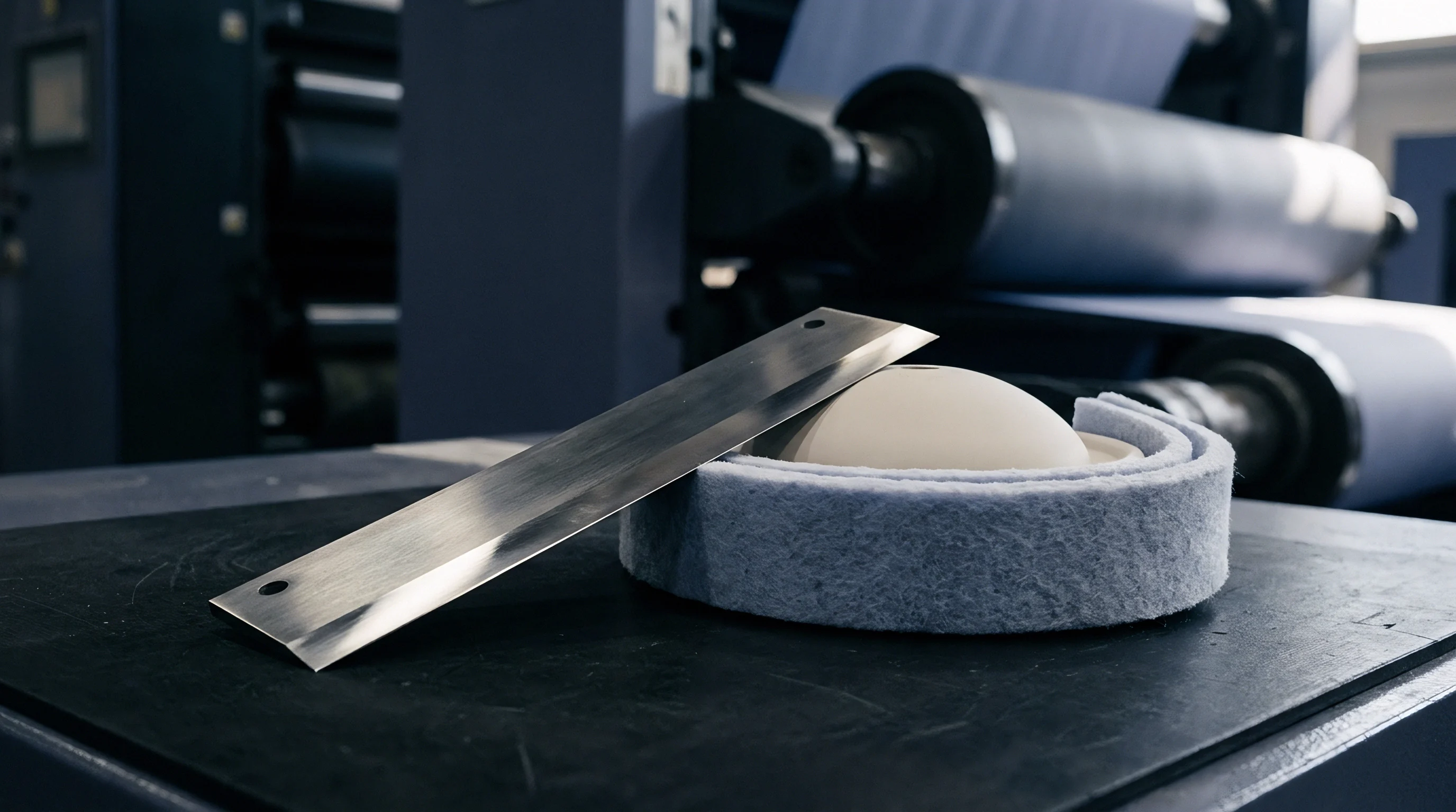
Circumferential Repeat Growth and Register Shifts
Dynamic growth alters repeat length on every revolution. Radial enlargement of 25 microns increases the tool circumference by approximately 0.157 mm per revolution. Mechanical friction generates heat.
Over a continuous run of 10,000 meters, this small circumferential enlargement shifts cut locations progressively forward relative to printed artwork. The converting line loses web alignment, driving cuts out of specification tolerances.
Gear wear increases register error. Pitch diameter divergence forces gear teeth into tight pitch-line interference. Drive gears experience tooth flank scrubbing, generating high-frequency mechanical vibration across the cylinder journals.
Mechanical vibration transfers directly onto the web, creating visible score chatter marks and variable cut depth across individual packaging blanks. Precision converting demands exact pitch alignment across all active processing stations.
Why Does Bearer Load Drift across Long Runs?
Downward hydraulic force balances internal tool separation forces during high-speed cutting. As thermal expansion drives cylinder bodies outward, hydraulic bearer rings experience intense resistance forces. Total load across bearing housings escalates beyond baseline settings.
Hydromechanical load increases of 30 percent to 50 percent occur within two hours of continuous line operation. Excess bearer force squeezes structural lubrication films out of journal bearings, accelerating mechanical wear.
Structural deflections compound registration errors. Rising counterforces flex cylinder shafts outward at their midpoints. Shaft bending opens the center gap between tool and anvil by 8 to 15 microns while bearer rings remain locked tight at outer edges.
Center web lanes experience loss of cut depth, while outer lanes suffer from crushing forces. Correcting center deflection through increased bearer loading amplifies journal stress without restoring uniform pitch geometry across the web.
DIN 16706 restricts circumferential repeat variation to one tenth of a millimeter across continuous fifty thousand meter production runs.
Standard delivery contracts governed by European Carton Makers Association guidelines assign full financial liability for score cracking and register deviation to the converter whenever thermal monitoring logs show tool temperatures exceeded standard pre-heat tolerances without dynamic mechanical compensation.

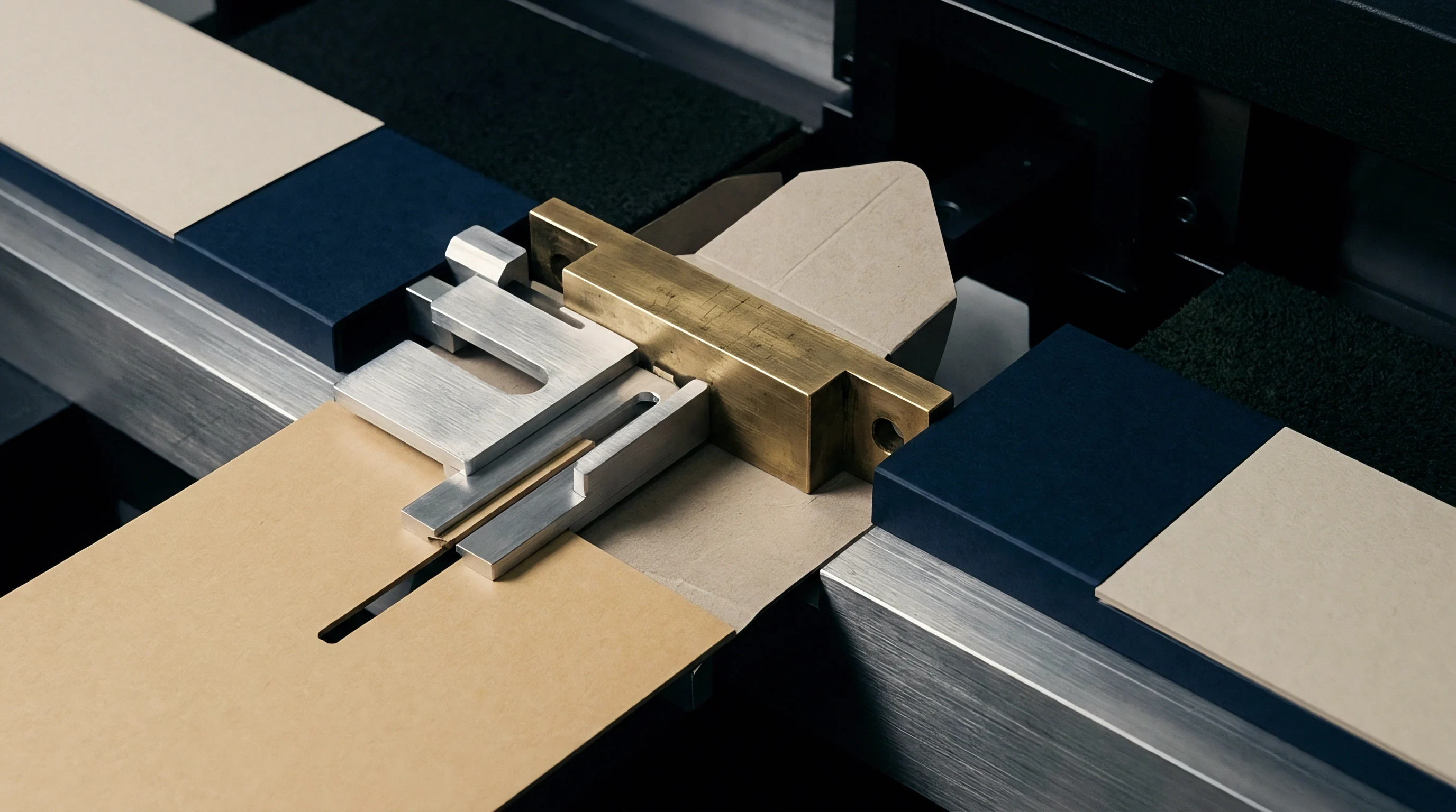
Anvil
Stabilizing dynamic tool geometry requires dedicated mechanical temperature regulation and hydraulic gap adjustment hardware. Chilled fluid stabilizes tool temperature. Circulating temperature-controlled media through internal core passages extracts friction heat directly at the source.
Active thermal management maintains metal cylinder dimensions within tight tolerances during continuous multi-shift production runs.
Active Temperature Management and Fluid Cooling
Internal cooling systems utilize spirally drilled liquid channels running directly beneath the tool surface and bearer shoulders. Chilled water or thermic oil flows through rotary joints at controlled velocities. Maintaining fluid inlet temperatures at 20 degrees Celsius with tight control tolerances prevents thermal expansion from exceeding critical thresholds.
Core temperature management arrests radial growth at less than 4 microns across continuous 24-hour manufacturing operations.
Hydraulic oil maintains force. Temperature regulation prevents tool body swelling, protecting blade sharpness and maintaining pitch circle dimensions. Fluid cooling eliminates thermal gradients across the cylinder face, maintaining flat, uniform profile geometry from shoulder to shoulder.
Converting lines running integrated fluid cooling systems achieve consistent cutting depth across all web channels without requiring manual operator intervention during run startup phases.
- Internal Fluid Cooling Capability requires continuous recirculating chilled media passages machined through the core to extract frictional heat directly beneath the cutting surface.
- Real-Time Bearer Load Transducers provide digital feedback on actual contact forces across side housings, warning press operators of thermal load escalation before mechanical damage occurs.
- Variable Gap Stepping Mechanics utilize eccentric bearing sleeves or hydraulic wedge systems to adjust cylinder centerline spacing in sub-micron increments during machine operation.
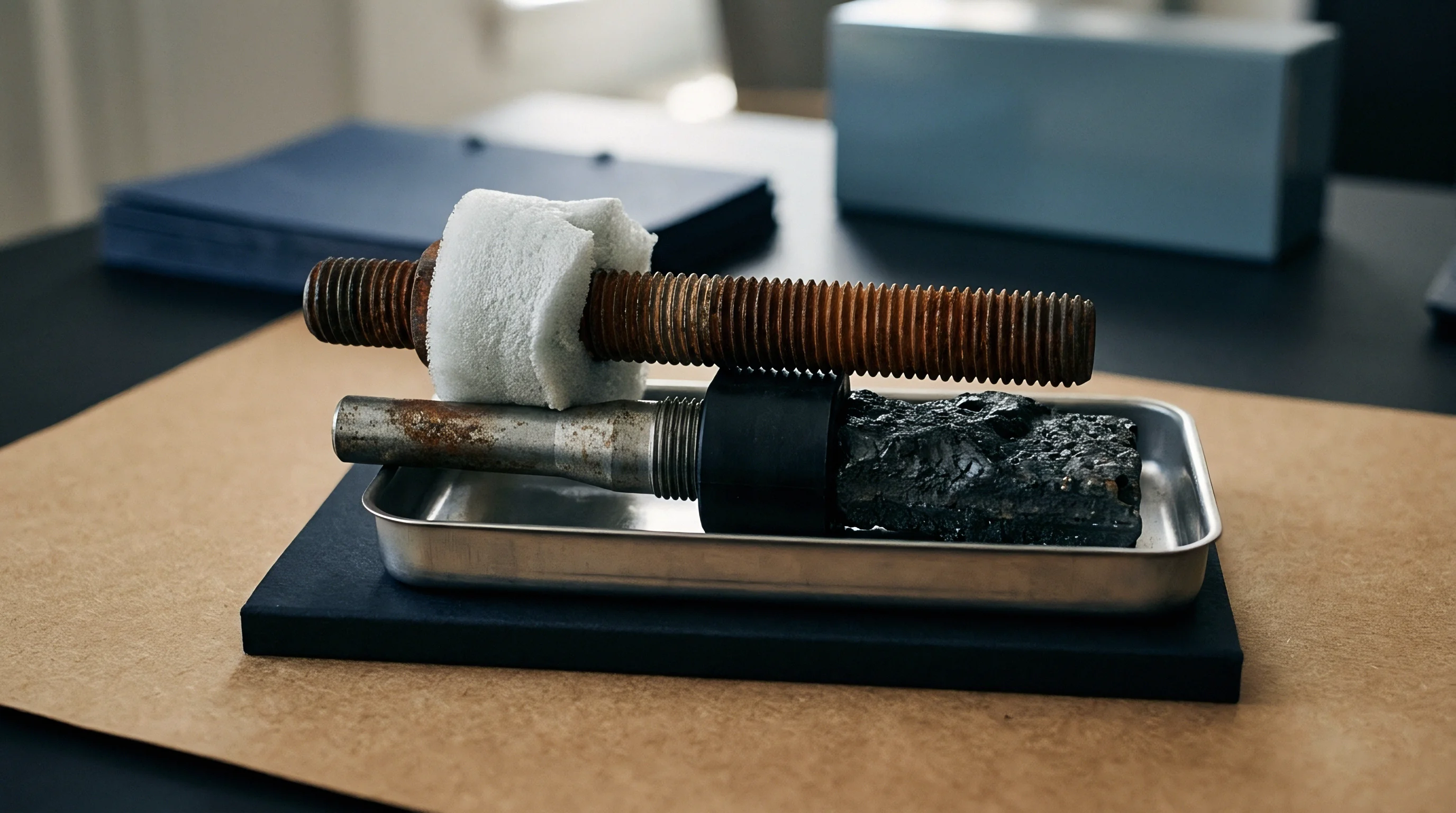
- Hardened Carbide Bearer Surface Coating prevents surface galling and dimensional wear across ring contact bands under extreme hydraulic preload forces.
Hydraulic Preload Stabilization Mechanics
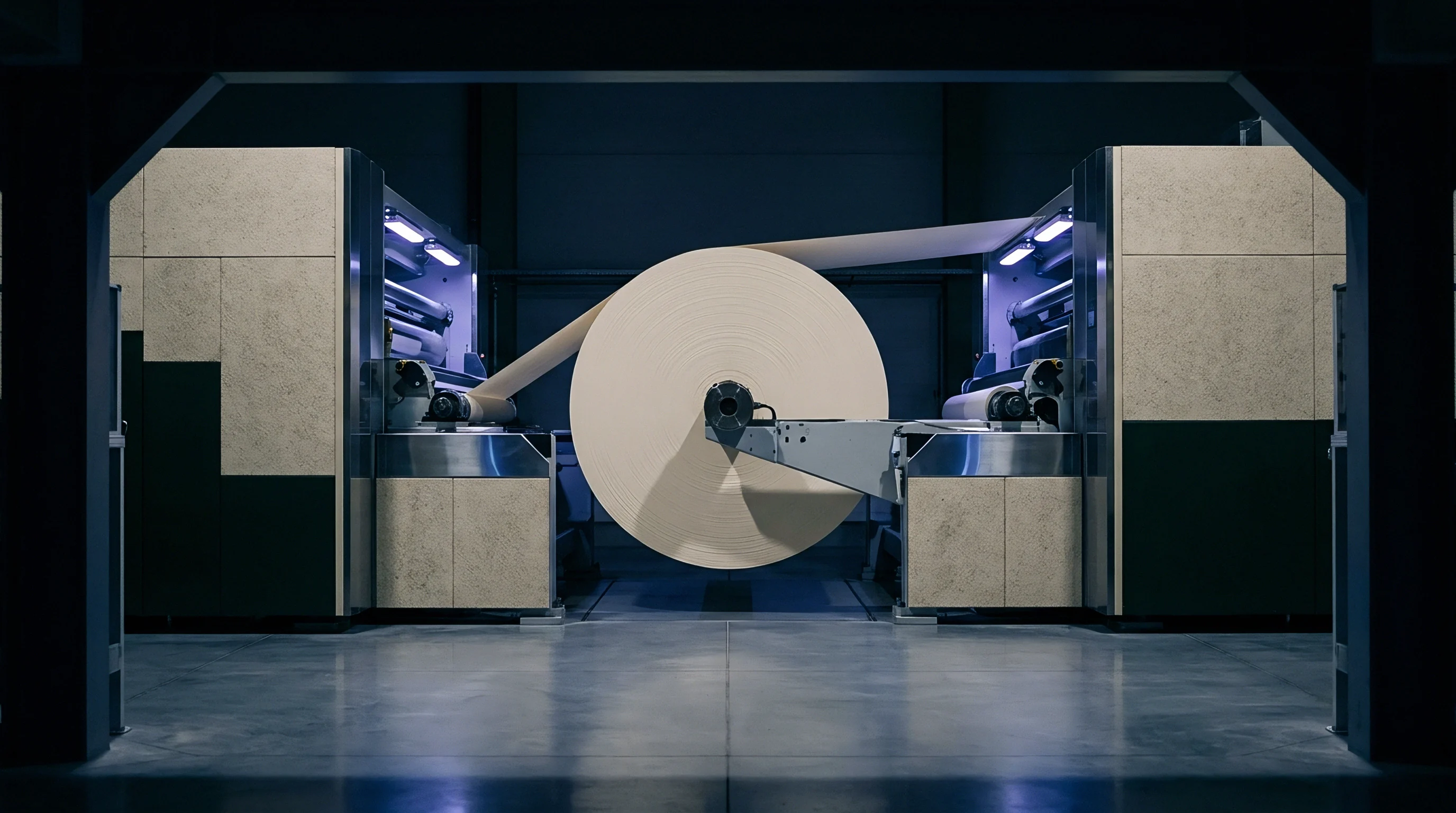
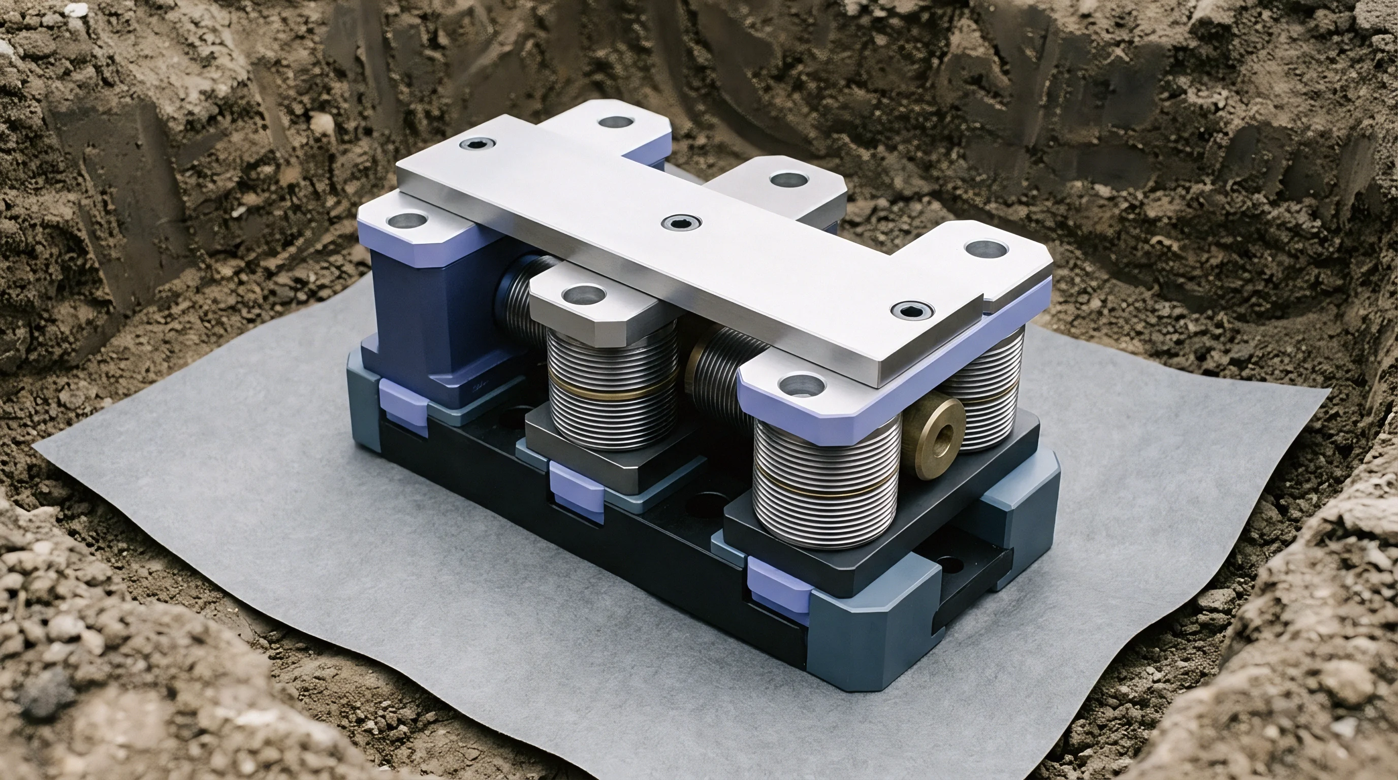
Variable gap adjustment mechanisms allow operators to adjust cylinder clearance during operation. Eccentric bearing housings driven by high-resolution stepper motors shift cylinder centers in increments down to 0.5 microns. When counterforce matrix creep causes loss of crease definition, the gap control system decreases clearance to maintain consistent creasing pressure without stopping the web line.
Proper calibration prevents scrap. Hydraulic counter-pressure cylinders absorb shock loads while holding bearer rings in firm contact. Closed-loop control systems monitor real-time force signals from load cells mounted in housing blocks.
When thermal growth increases bearer pressure beyond nominal thresholds, the hydraulic system relieves line pressure automatically, keeping bearer contact stress within safe operating limits.
Whether internal cooling channels eliminate localized thermal hot spots around dense knife layouts without inducing internal stress across the tool steel body remains an unresolved engineering question across high-speed packaging plants.

Procedure
Mathematical modeling allows converting engineers to calculate dynamic clearance equilibrium across extended production cycles. Tool wear accelerates rapidly. Combining steel thermal expansion formulas with polymer creep equations establishes a net gap error prediction model.
This calculation guides setup parameters and active compensation settings before committing raw board stock to production.
Mathematical Model for Net Clearance Equilibrium
Radial steel thermal growth follows linear physical expansion mechanics based on core temperature rise:
delta r_steel = r_0 CTE delta T
Where r_0 represents nominal cylinder radius (130 mm), CTE equals 10.8 x 10^-6 / K for AISI D2 tool steel, and delta T equals an observed 18 Kelvin core temperature increase. The resulting radial swell equals 0.0253 mm (25.3 microns).
Simultaneously, viscoelastic matrix creep reduces effective polymer anvil thickness over operational time:
delta h_creep = h_0 C_creep log10(N / 1000)
Where h_0 represents nominal matrix thickness (10 mm), C_creep equals a material creep coefficient of 0.0018 per decade, and N represents total impression count (200,000 cycles). The resulting height reduction equals 0.0414 mm (41.4 microns).
Net operating gap change represents the sum of steel swell and polymer creep:
delta Gap = delta r_steel – delta h_creep
delta Gap = 25.3 microns – 41.4 microns = -16.1 microns
The calculation reveals a net gap expansion of 16.1 microns. Thermal steel growth compensates for part of the polymer matrix loss, but matrix creep dominates over long runs. Net impression force drops, causing creasing failure unless corrected by hydraulic gap adjustment systems.
| Run Hour | Core Temp Rise (K) | Steel Swell (μm) | Matrix Creep (μm) | Net Gap Error (μm) | Hydraulic Offset (μm) |
|---|---|---|---|---|---|
| 0.0 | 0.0 | 0.0 | 0.0 | 0.0 | 0.0 |
| 1.0 | 8.5 | 11.9 | 12.2 | -0.3 | 0.0 |
| 2.0 | 14.2 | 19.9 | 21.8 | -1.9 | +2.0 |
| 4.0 | 17.5 | 24.6 | 31.4 | -6.8 | +7.0 |
| 6.0 | 18.0 | 25.3 | 37.2 | -11.9 | +12.0 |
| 8.0 | 18.0 | 25.3 | 41.4 | -16.1 | +16.0 |
| Data calculated for a 260 mm diameter D2 rotary tool running at 280 m/min on 350 gsm folding boxboard with a 95 Shore A polyurethane anvil cover. | |||||
Make-Ready Thermal Calibration Protocol Sequence
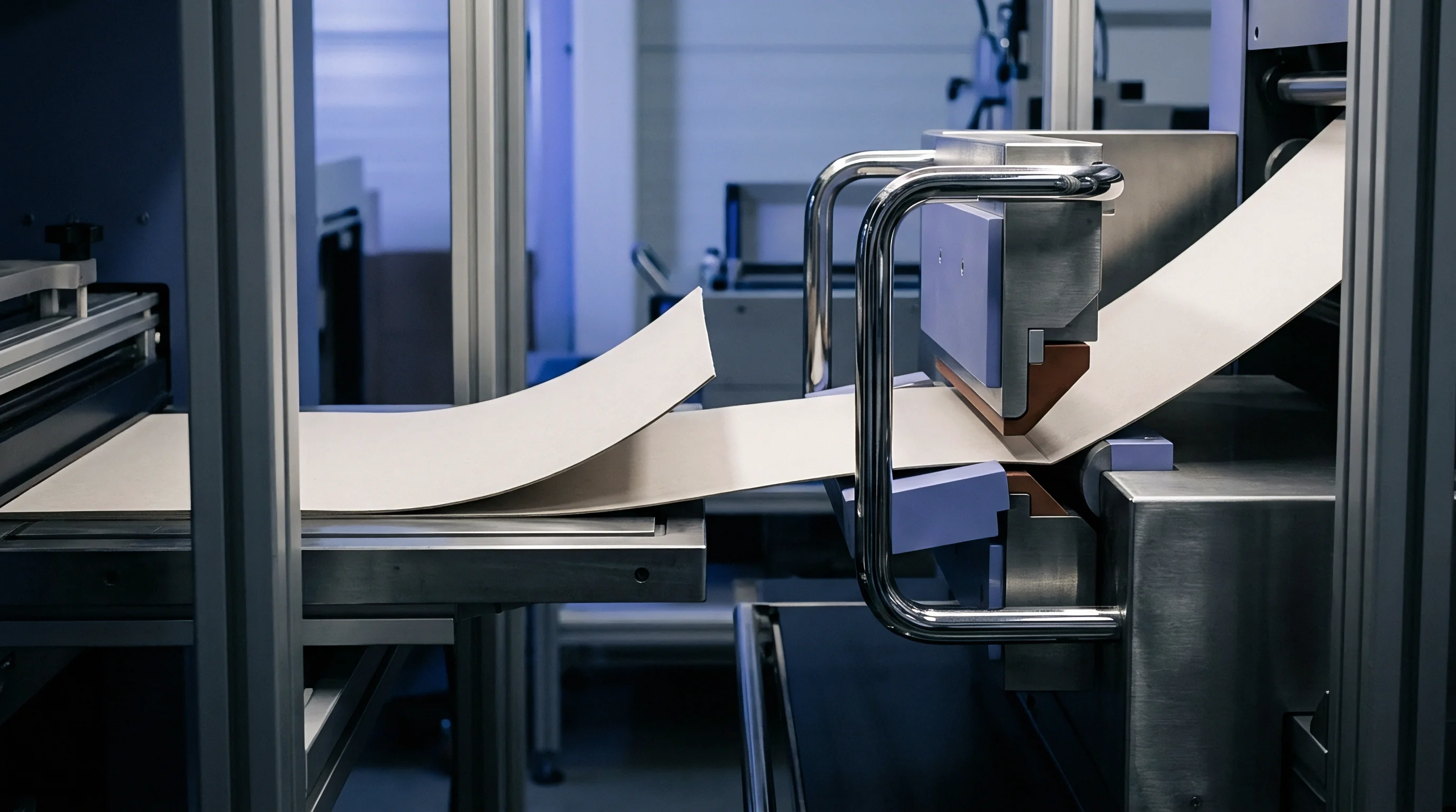
Executing systematic setup steps ensures line stability before full-speed manufacturing begins. Precision requires thermal equilibrium.
- Establish baseline zero gap settings using feeler gauge blocks while the converting machine remains at cold ambient baseline temperature.
- Circulate temperature-regulated fluid through internal cylinder passages for twenty minutes prior to mounting cutting tools.
- Monitor bearer ring contact pressure using integrated digital load sensors until readings stabilize across both operating side housings.
- Apply preliminary hydraulic preload to lock bearer rings in rolling contact at thirty percent of nominal running web speed.
- Execute continuous test run on scrap board stock for five thousand impressions, tracking surface temperature rise via non-contact infrared sensors.
- Input calculated net clearance compensation figures into the electronic gap adjustment controller to lock in target creasing force values.
Tool pre-warming at low idling speed reduces early-run score calibration drift significantly.
Incremental bearer pressure adjustments applied before tool steel reaches core thermal equilibrium double the wear rate across cutting rule edges.

Reserve
Tooling wear and scrap rates drive total converting run economics. Capital protection demands tight management of thermal and mechanical variables. Unmanaged dynamic clearance variations accelerate blade failure, forcing premature tool re-grinding and increasing scrap rates across high-speed packaging lines.
Tooling Maintenance Economics and Resharpening Cycles
Excessive cutting impact forces dull blade edges rapidly. Operating uncompensated tool sets reduces blade life from 5,000,000 impressions to fewer than 1,800,000 impressions before requiring full resharpening servicing. Re-tooling a four-up rotary die unit costs between 8,500 and 14,000 EUR in direct vendor re-grinding expense, accompanied by four hours of unscheduled press downtime.
Frequent re-grinding removes hardened steel surface layers, shortening overall tool body life. A tool body capable of sustaining six re-grind cycles under thermally controlled conditions survives only two re-grind cycles when subjected to severe thermal overload impact damage. Capital expenditure budgets must absorb premature tool replacement costs, increasing amortization charges per thousand finished cartons.
Chilled oil temperature management extends die blade life between resharpening intervals substantially.
Scrap Mitigation and Financial Ledger Impact
Substandard creasing profile quality generates severe downstream financial liability. Shallow score lines cause carton jamming on high-speed automated packaging lines at customer facilities. A rejected delivery batch of 500,000 folding cartons produced from 350 gsm coated boxboard represents a direct material loss exceeding 22,000 EUR, plus freight and administrative penalty charges.
Active thermal regulation and automated gap control systems protect converting margins. Allocating funding toward internal liquid cooling hardware and dynamic hydraulic adjustment systems pays for itself within six months of continuous operations on high-speed carton lines through waste reduction and extended tooling operational lifespans.