Correlating Ultrasonic Attenuation Decay Rates with Paperboard Crease Delamination Depth
Ultrasonic attenuation decay rates directly quantify paperboard crease delamination depth, enabling real-time inline verification of folding stiffness.


Pulse
High-frequency ultrasound through paperboard structures relies on longitudinal stress waves generated by piezoelectric ceramic elements. Acoustic energy traveling through undamaged solid bleached board (SBB) or folding boxboard (FBB) Encounters a uniform matrix of bonded cellulose fibers. When the sound field encounters internal ply separations, energy reflects at the fiber-air interfaces, attenuating the transmitted signal amplitude.
Transducer selection determines spatial resolution across thin cartonboard calipers. Frequencies between 2.25 MHz and 10 MHz resolve micro-scale internal shearing without suffering total absorption within porous fibrous plies.
Board density dictates acoustic impedance. Phase velocity drops suddenly.

Transducer Coupling across Multilayer Paperboard Plies
Contact measurement requires acoustic energy transmission across the air boundary between transducer faces and top linerboard. Dry contact rollers or dry-coupled elastomeric delay lines compress slightly under mechanical load to eliminate microscopic air pockets. Applied contact pressure must stay within bounded limits.
Excess pressure crushes the top coating, while insufficient pressure introduces dry boundary impedance spikes. Silicone delay line tips operating at 0.35 MPa contact pressure achieve steady acoustic transmission through clay-coated board surfaces without leaving residue or altering surface tension.
Peak transducer transmission efficiency across dry board requires a contact pressure of 0.35 MPa using a high-viscosity silicone couplant at 23 degrees Celsius.
Pitch-catch configurations position transmitting and receiving probes on opposite sides of the crease. Signal attenuation rises sharply as internal plies detach during mechanical creasing. Ultrasonic wave propagation along the thickness axis (Z-direction) provides a sensitive measure of delamination depth.
Sound speed varies across machine direction (MD) and cross-machine direction (CD) fibers. Anisotropic fiber alignment requires strict orientation alignment during calibration runs.
| Substrate Grade | Nominal Caliper (µm) | Density (g/cm³) | Longitudinal Velocity (m/s) | Acoustic Impedance (MRayl) | Baseline Attenuation (dB/mm) |
|---|---|---|---|---|---|
| Solid Bleached Board (SBB) | 350 | 0.82 | 2450 | 2.01 | 1.85 |
| Folding Boxboard (FBB) | 450 | 0.68 | 1980 | 1.35 | 2.40 |
| Coated Recycled Board (CRB) | 400 | 0.74 | 2100 | 1.55 | 3.10 |

Acoustic Wave Reflection at Layer Interfaces
Mechanical impedance boundaries within solid bleached board drive internal acoustic reflections. Density variations between chemical pulp linerboards and mechanical pulp middle plies create inherent reflection coefficients. Uncreased board exhibits low baseline amplitude loss.
When scoring dies force middle plies apart, air-filled micro-fissures form within the interior structure. Air pockets possess an acoustic impedance near 0.0004 MRayl, creating an almost complete reflection barrier compared to the solid board matrix. Energy leaks through fractured fibers.
Reflected signal amplitude correlates directly with total delaminated surface area within the crease volume. Multi-ply cartonboards experience layered shear failure across specific weak bonding planes. The depth of these delaminated planes governs bending stiffness during high-speed carton erection.
Acoustic time-of-flight measurements isolated to the first arrived longitudinal wave allow precise mapping of crack depth along the crease axis.
Board suppliers frequently claim that variations in acoustic transmission stem entirely from environmental relative humidity shifts during transit rather than uneven fiber bonding across internal plies.

Blade
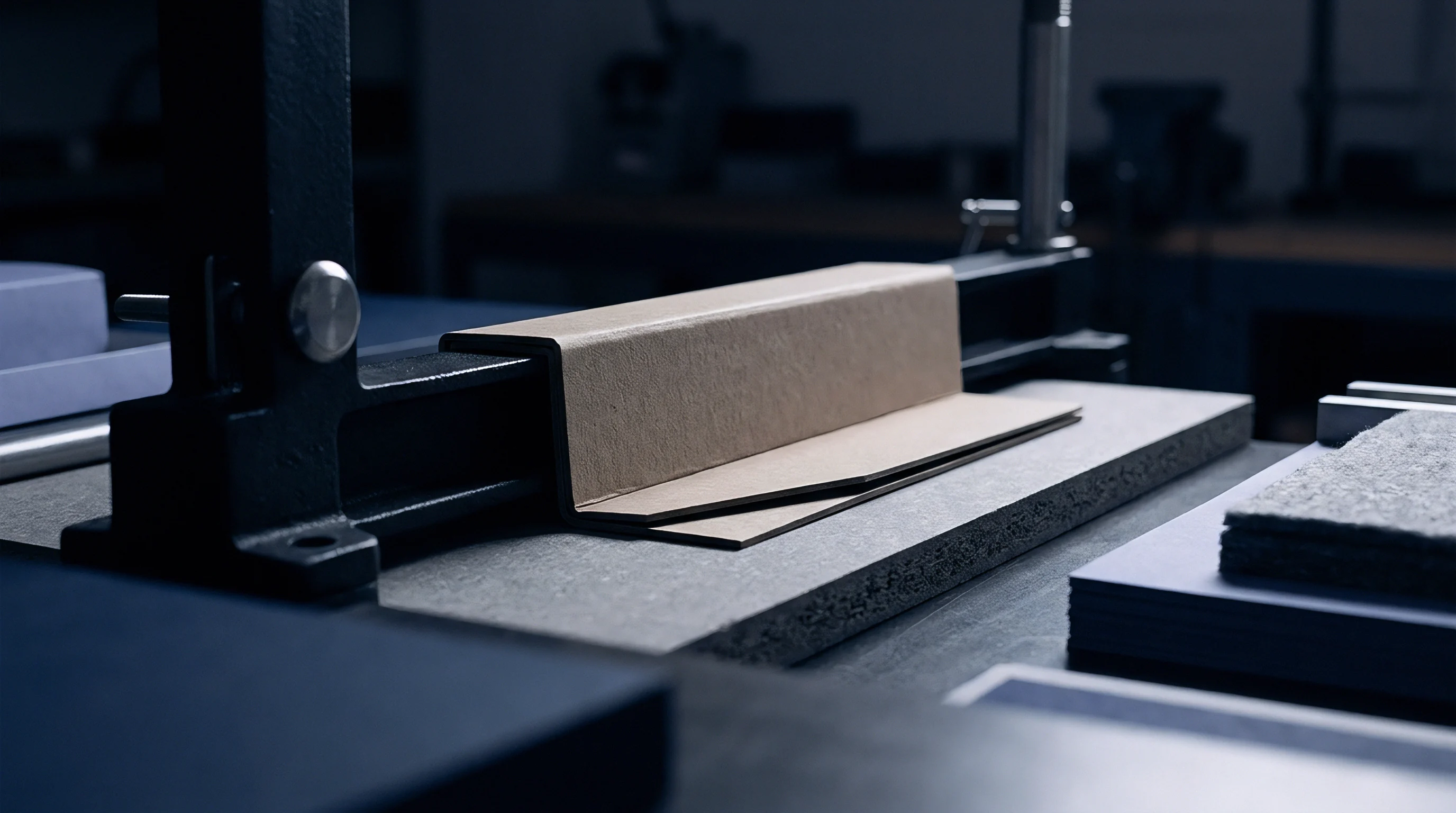
Mechanical creasing sets the initial strain field within paperboard prior to carton folding operations. Creasing rules depress the sheet into a female die channel, creating localized shear stress. This controlled mechanical damage forces internal plies to separate into discrete layers.
Crease depth dictates whether a carton folds cleanly at 90 or 180 degrees without rupture.
Matrix selection governs channel geometry. Deep scores reduce bending resistance.

Scoring Rule Penetration and Internal Shear Failure
Penetration depth during the creasing stroke forces the middle fibrous plies to rupture under high shear stress. The top liner undergoes tensile elongation, while the bottom liner suffers compressive deformation. Proper creasing destroys Z-direction tensile integrity in a localized region without breaking the outer printable surfaces.
The resulting delamination zone acts as a mechanical hinge during box assembly.
- Measure uncreased paperboard caliper using an ISO 534 dead-weight micrometer to set baseline substrate thickness.
- Select male creasing rule width and female matrix channel width matching sheet caliper and fiber orientation.
- Adjust die cutter press tonnage to achieve target penetration depth equal to sixty percent of nominal caliper.
- Run a calibration batch and immediately measure score bending resistance using an ISO 2493 stiffness tester.
- Verify internal ply separation depth via cross-sectional optical microscopy before locking press impression parameters.

Channel Width Ratios Governing Delamination Depth
Female matrix clearance determines the lateral spread of internal ply separation across the score axis. Narrow channels concentrate shear forces in a narrow central band, generating deep but localized delamination. Wide matrix channels distribute bending forces over a broader zone, yielding shallow ply separation.
Broad dies widen delamination zones.
ISO 187 conditioning mandates 23 degrees Celsius and 50 percent relative humidity, where a 2 percent moisture drift shifts score bending stiffness by 14 percent.
Die pressure creates local compaction. Internal ply separation depth must reach at least forty percent of total caliper to prevent surface cracking on high-rigidity folding boxboard. Excessive rule depth crushes the board structure entirely, destroying score recovery force.
Ultrasonic attenuation measurements capture this transition from functional ply separation to destructive structural collapse instantly during press make-ready.
Matching the creasing rule geometry to the natural ply shear resistance of the substrate prevents outer liner cracking while maintaining adequate internal score delamination.


Decay
Acoustic signal attenuation across a creased zone reflects structural energy losses from micro-voids. As sound pulses pass through delaminated plies, spatial amplitude decay follows an exponential reduction path. Quantifying this decay rate yields a continuous metric directly proportional to internal crack penetration depth.
High frequencies resolve micro fissures. Signal loss tracks void volume.

Why Do Acoustic Attenuation Rates Shift across Machine Direction Creases?
Anisotropic elastic moduli in machine-direction fibers cause asymmetrical wave scattering along the score line. Machine direction (MD) creases cut perpendicular to aligned fibers, creating sharp, clean delamination planes. Cross-machine direction (CD) creases force sound waves across disordered fiber networks, generating diffuse scattering.
Wave propagation perpendicular to MD creases exhibits higher baseline attenuation coefficients due to enhanced fiber end reflections.
Acoustic wave scattering within delaminated plies rises sharply once micro-crack voids exceed transducer wavelength.
High-frequency ultrasound scattering increases when void dimensions approach the acoustic wavelength. For a 5 MHz signal traveling at 2000 m/s, the nominal wavelength in board is 400 µm. Micro-cracks measuring between 50 µm and 300 µm scatter sound energy, causing exponential amplitude decay.
Measuring amplitude loss across multiple discrete receiver positions yields the spatial attenuation coefficient alpha.
Mathematical Formulation of Exponential Amplitude Reduction
Sound energy loss through fractured paperboard plies obeys a logarithmic drop in peak amplitude. The wave amplitude A at propagation distance x relates to initial amplitude A_0 through the exponential relation A = A_0 exp(-alpha x). The attenuation coefficient alpha, expressed in Nepers per millimeter or decibels per millimeter, increases monotonically with delamination depth.
| Substrate | Caliper (µm) | Crease Depth (% Caliper) | Delamination Depth (µm) | Attenuation Coefficient alpha (dB/mm) | Score Bending Stiffness (mN·m) |
|---|---|---|---|---|---|
| Solid Bleached Board | 380 | 30 | 114 | 4.2 | 185 |
| Solid Bleached Board | 380 | 50 | 190 | 8.7 | 110 |
| Solid Bleached Board | 380 | 70 | 266 | 14.5 | 45 |
| Folding Boxboard | 450 | 30 | 135 | 5.8 | 210 |
| Folding Boxboard | 450 | 50 | 225 | 11.4 | 130 |
| Folding Boxboard | 450 | 70 | 315 | 19.1 | 55 |
Consider a 450 µm folding boxboard sample evaluated under pitch-catch testing. Initial amplitude A_0 across uncreased board measures 800 mV at a fixed transducer spacing of 10 mm. Across a creased section with 50 percent delamination depth, the received signal amplitude drops to 215 mV over the same path length.
Calculating the attenuation coefficient yields alpha = -ln(215 / 800) / 10 mm = 0.1315 Np/mm, equivalent to 1.14 dB/mm above baseline. Calibrating this value against empirical destructive micro-sectioning confirms an internal crack depth of 225 µm.
Amplitude decay follows logarithmic decay. Board moisture alters signal speed.
Engineers remain uncertain whether non-linear viscoelastic recovery of compacted fibers within the crease zone permanently distorts acoustic attenuation decay curves over multi-day storage periods.


Dossier
Non-destructive evaluation protocols require systematic verification of signal baseline stability. Establishing continuous inline monitoring requires sensor arrays mounted directly on die-cutter stripping stations or folder-gluer entry sections. Real-time acoustic data provides instant feedback on score quality without stopping production runs.

Inline Measurement System Calibration and Probe Array Setup
Standardization of transducer contact pressure prevents false readings driven by dry boundary resistance. Spring-loaded mounting blocks ensure constant mechanical loading against moving sheets. Array transducers spaced at 5 mm intervals across the web capture spatial variations in crease quality across multi-up die layouts.
Sensor arrays require rigid alignment.
Calibration curves for attenuation decay fail when surface varnish fills outer micro-fissures without restoring ply bond integrity.
Surface roughness scatters dry coupling. Converting lines run at speed.
- Signal Attenuation Artifacts arise when localized board caliper variations mimic internal ply separation signal drops.
- Transducer Misalignment Errors occur when sheet flutter changes probe contact angle relative to the web plane.
- Couplant Viscosity Drift alters energy transfer efficiency as ambient temperature fluctuates on the converting floor.
- Surface Roughness Interference introduces high-frequency noise when un-coated recycled board surfaces pass under dry contact probes.

Verification Requirements for Non Destructive Folding Boxboard Qualification
Quality assurance audits on high-speed packaging lines demand logged acoustic attenuation profiles. Continuous data logging pairs each sheet ID with localized crease attenuation values. Deviations exceeding plus or minus 1.5 dB/mm from target thresholds automatically trigger reject gates downline.
Unchecked micro cracks split folds.
Incorporating ISO 187 preconditioning mandates into standard purchase agreements shifts financial liability for score cracking defects directly to the converting facility whenever relative humidity strays outside specified limits.


Tariff
Converting economics hinge on minimizing waste generated by deep crack propagation during automated carton folding. Inline acoustic sensing eliminates manual off-line stiffness testing, reducing make-ready waste by up to sixty percent. Catching incorrect creasing parameters early prevents large-scale pallet scrap.

Landed Run Costs and Inline Defect Waste Mechanics
Unchecked score fracturing increases reject rates at the gluing line, raising total job costs. High-speed erecting machines jam when crease stiffness varies across a single batch. Implementing automated ultrasonic monitoring adds initial hardware expense but lowers net operational scrap rates from 2.5 percent to below 0.4 percent across multi-million run production jobs.
- Substrate Fiber Thickness limits maximum achievable signal penetration without triggering signal loss.
- Score Stiffness Limits dictate minimum allowable attenuation coefficients required for clean 90-degree carton folding.
- Inline Probe Frequency must align with substrate density to maintain optimal spatial resolution across thin calipers.
- Recyclability Grading Compliance mandates that internal physical delamination methods eliminate the need for synthetic cross-linking primers.
Extended Producer Responsibility Fees for Delaminated Structural Packaging
Modulated packaging eco-modulations penalize laminated multi-material structures that fail recyclability screening. Mechanical delamination achieved purely through optimized creasing retains mono-material status, qualifying for lower extended producer responsibility fee tiers. Converting lines that maintain structural score integrity without applying external poly-coatings lower landed unit costs while fulfilling regional packaging waste directives.
Incorrectly specifying creasing parameters leads to severe score splitting during high-speed carton erecting, triggering complete batch rejections and costly line downtime charges.