Paperboard Creasing Mechanics and Physical Quality Inspection Fundamentals
Optimizing rule depth and matrix channel width induces internal ply delamination, preventing top liner crack failures during high-speed carton folding.

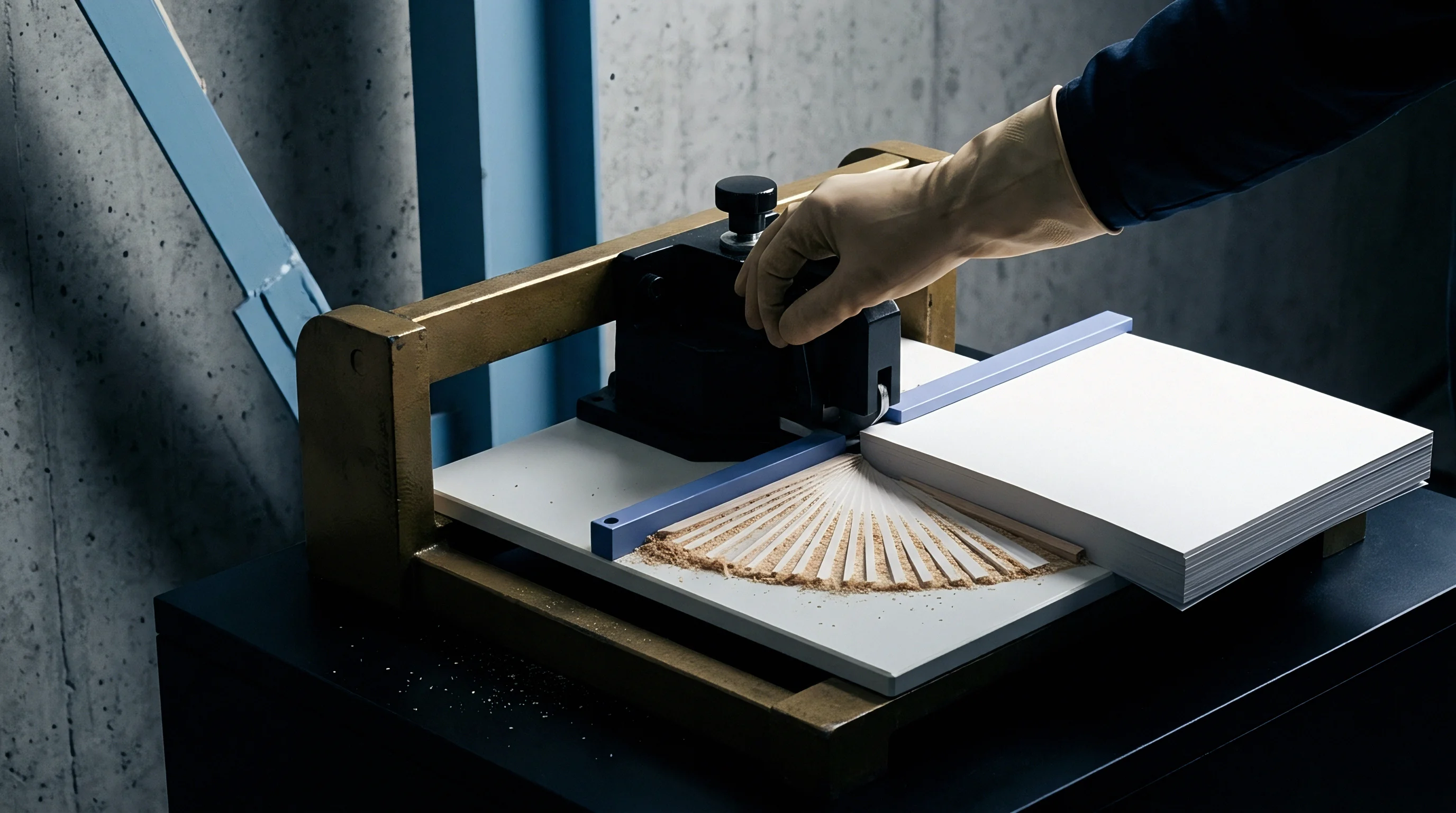
Structure
Paperboard converting relies on controlled mechanical deformation to form clean, predictable folding joints. If an uncreased sheet is folded without prior scoring, the outside liner takes the full brunt of tensile strain while the inner plies compress abruptly. That unmanaged stress splits the outer liner, cracks printed graphics across the fold line, and creates irregular buckling along the inside corner.
Creasing avoids this failure by breaking down the internal structure of the sheet along a narrow, designated score line.
Solid bleached sulfate, folding boxboard, and coated recycled board react differently to creasing tools because their ply structures differ fundamentally. In multi-ply boards, outer plies of bleached chemical pulp enclose a bulkier core of mechanical pulp or recycled fibers. When the die closes, a rounded steel male rule pushes the board down into a counter-die channel, concentrating vertical compression directly beneath the rule tip and generating high shear stress between the plies.
Crease durability relies on controlled internal ply shear produced by localized mechanical compression.
This shear force fractures the hydrogen bonds holding the fibrous layers together, deliberately delaminating the core. The delaminated zone acts as a built-in hinge: when the carton blank folds to ninety or one hundred eighty degrees, the separated inner plies buckle inward to form a compact crease bead. The outer liner can then stretch over the internal hinge without tearing or degrading print across the finished fold.

Mechanical Strain Distributions during Tool Penetration
Deformation happens in three stages during the creasing stroke. First, the sheet bends elastically across the opening of the female matrix channel. Second, vertical compression sets in under the rule tip while sharp inter-ply shear develops along the channel shoulders.
Finally, permanent plastic deformation breaks fiber-to-fiber bonds through the core plies while leaving the top liner’s tensile capacity intact.
Caliper, fiber length, and moisture levels dictate the window between a sound internal shear and surface rupture. Dense outer liners tolerate higher elongation before tearing, whereas stiff, short-fibered mechanical cores demand wider delamination zones to absorb compressive load. High moisture softens inter-fiber bonding, yielding spongy creases that hold little folding memory, while overly dry board turns brittle and fractures on the press.
A simple surface indentation will not prepare a sheet for clean folding. Without internal delamination, the board bends like a solid beam, shifting maximum tensile strain straight to the outer face. The sole mechanical purpose of creasing is to lower the bending resistance of the score line relative to the flat panel beside it.
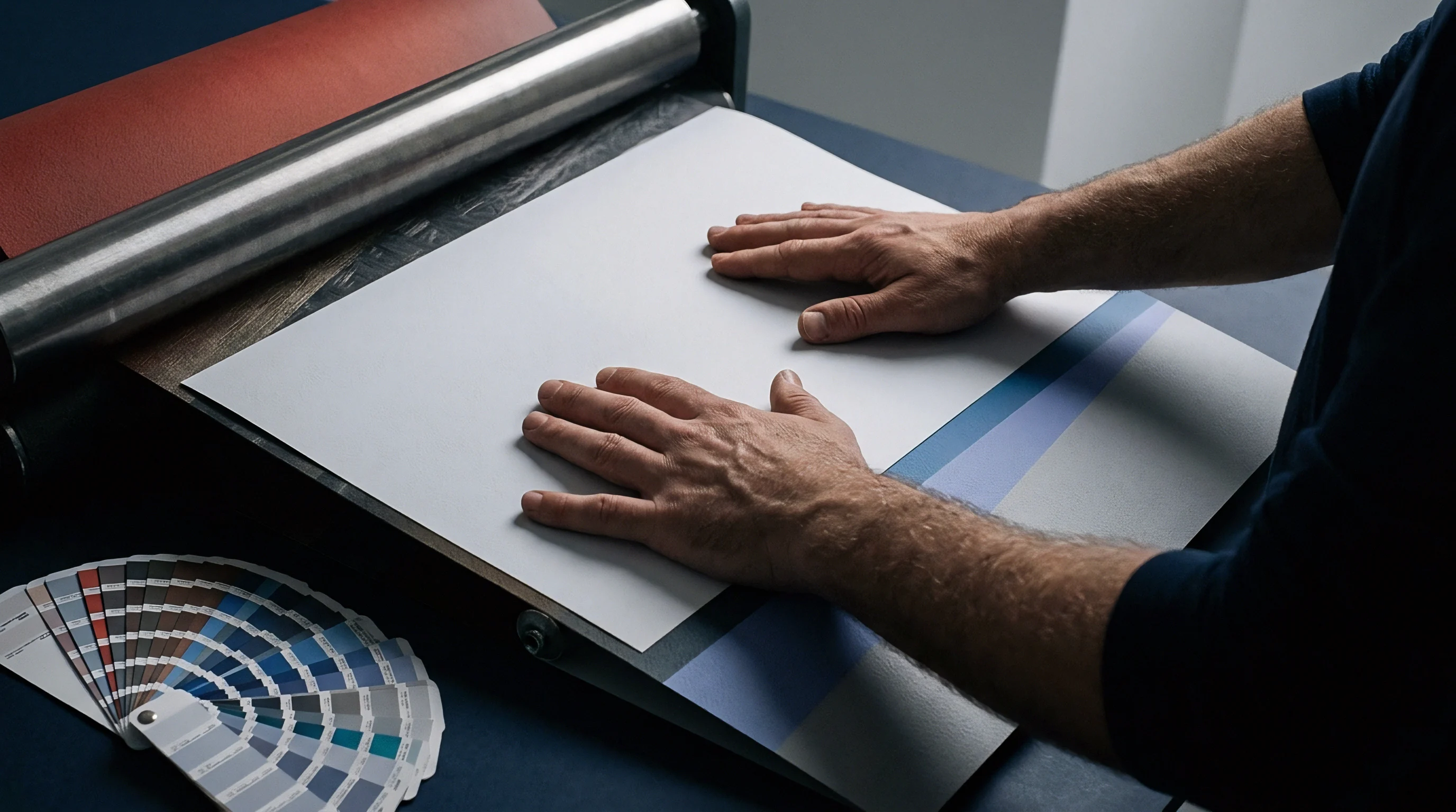
Groove
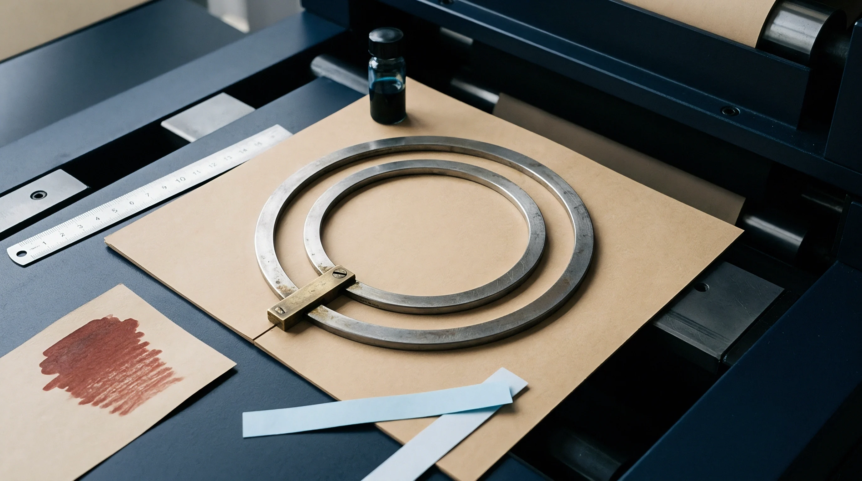
Matching the male creasing rule to the female channel determines fold quality on the converting floor. This tooling combination governs the width and depth of the delamination pocket formed inside the sheet. Rule width, rule height, counter-channel width, and channel depth operate as a single mechanical system controlling how shear forces distribute through the caliper.
Male rules feature rounded steel profiles measured in point gauge, where one point equals 0.353 millimetres. Most packaging dies run two-point (0.71 mm) or three-point (1.05 mm) rules. The counter matrix ~ cut from pressboard, phenolic board, or milled steel plates ~ must accommodate the rule profile plus twice the compressed board thickness driven into the groove.
Sizing female channels requires calculating dimensions relative to fiber direction. For score lines parallel to the board’s machine direction, channel width is set to 1.5 times the caliper plus the rule thickness. Across the grain, channel width expands to 1.7 times the caliper plus rule thickness.
Channel depth matches nominal board caliper directly.
On a 450-micrometre (0.45 mm) folding boxboard creased across the grain with a 2-point (0.71 mm) rule, the formula gives 1.7 × 0.45 mm + 0.71 mm = 1.475 millimetres. Die makers round this to a standard 1.50 millimetre channel width, paired with a channel depth of 0.45 millimetres.
| Substrate Caliper (mm) | Rule Gauge (pt / mm) | With-Grain Channel Width (mm) | Cross-Grain Channel Width (mm) | Matrix Channel Depth (mm) |
|---|---|---|---|---|
| 0.30 to 0.38 | 2 pt / 0.71 mm | 1.20 to 1.30 | 1.30 to 1.40 | 0.30 to 0.35 |
| 0.40 to 0.48 | 2 pt / 0.71 mm | 1.30 to 1.40 | 1.40 to 1.55 | 0.40 to 0.45 |
| 0.50 to 0.58 | 3 pt / 1.05 mm | 1.80 to 1.90 | 1.90 to 2.05 | 0.50 to 0.55 |
| 0.60 to 0.75 | 3 pt / 1.05 mm | 1.95 to 2.20 | 2.10 to 2.35 | 0.60 to 0.70 |

Tooling Failures and Geometry Mismatches
Incorrect tooling setup produces immediate defects on press and downstream gluers. When groove dimensions deviate from target calculations, the applied force quickly exceeds the board’s structural tolerance.
- Liner Splitting occurs when matrix width drops below board thickness plus rule gauge, creating excessive tensile stress.
- Board Rolling happens when the channel width spans too wide, preventing localized ply delamination during impact.
- Shear Rupture surfaces when matrix depth sits too shallow, crushing plies instead of encouraging internal displacement.
- Crease Unraveling results from inadequate rule impression force, leaving the hinge elastic rather than permanently deformed.
Off-center creasing often traces to operator alignment errors during make-ready or thermal expansion across the die plate.
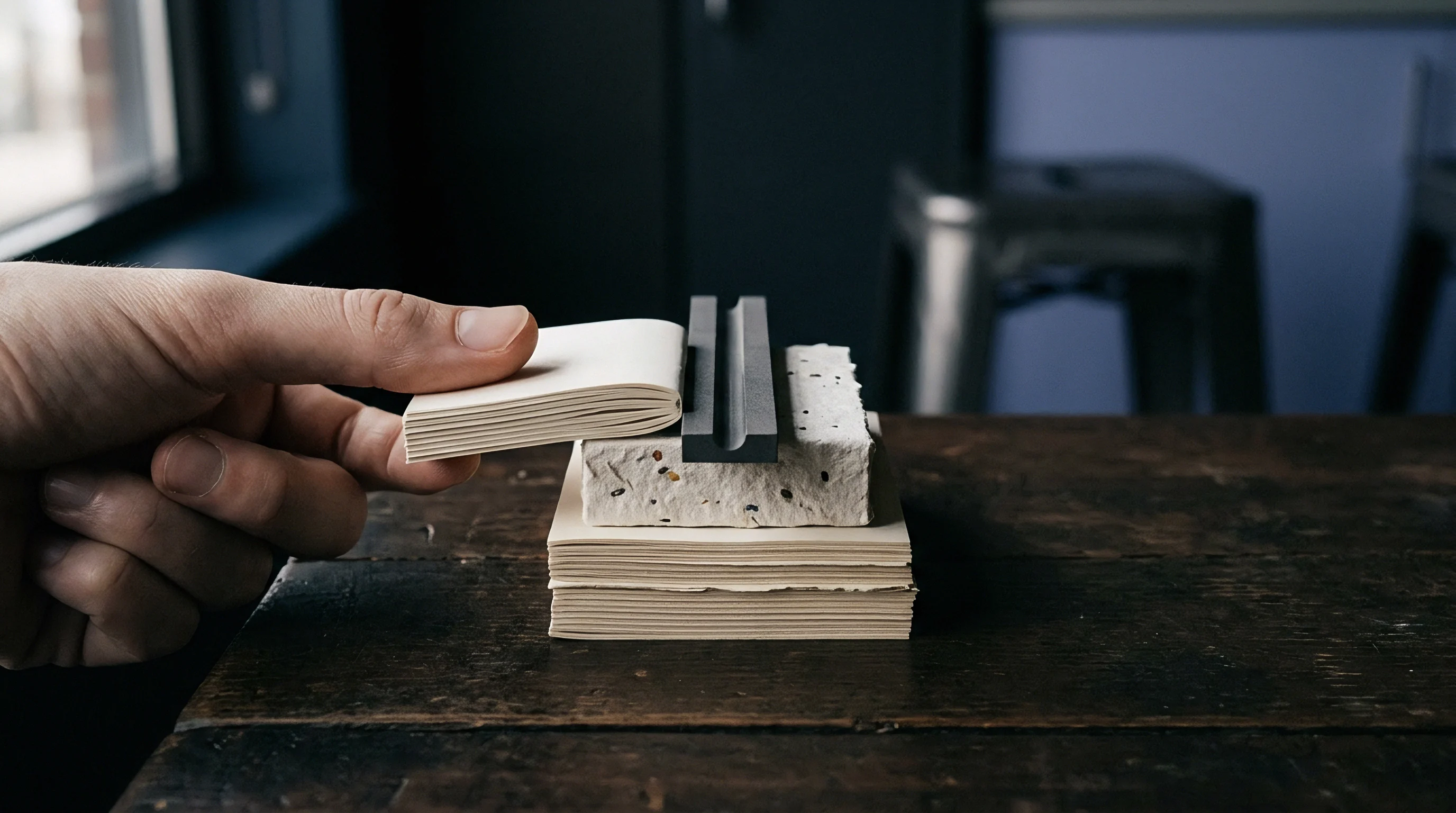
Stiffness
Measuring the torque needed to bend a score line gives an objective baseline for joint quality. Quality control relies on bench instruments to confirm that creasing has reduced flexural resistance without crushing or tearing the substrate. Bending moment testing measures the exact resistance encountered when deflecting a scored sample through a set angle.
Instruments like the L&W Crease Tester or Taber V-5 evaluate both the uncreased board and the creased score line at a fifteen-degree deflection angle in line with ISO 2493. Comparing the creased moment against the uncreased baseline gives the crease stiffness ratio, reported as a percentage.
Calculate crease stiffness ratio (Rb) using the formula:
Rb = (Mc / Mu) × 100
where Mc represents the bending moment of the creased score line in millinewton-meters, and Mu represents the bending moment of the uncreased board in the same grain orientation. Optimal creasing performance achieves an Rb value between 30 percent and 50 percent. Values above 60 percent generate excessive resistance on automated cartoning machinery, causing machine jams or bowed package walls.
Values below 20 percent indicate severe structural degradation, leading to weak score lines that collapse under stacking loads.
ISO 2493 specifies a fifteen-degree bending angle for evaluating crease resistance on automated packaging lines.
| Paperboard Grade | Grammage (g/m²) | Uncreased Moment MD (mNm) | Creased Moment MD (mNm) | Target Stiffness Ratio (%) |
|---|---|---|---|---|
| Solid Bleached Sulfate (SBS) | 300 | 18.5 | 6.8 | 36.7 |
| Folding Boxboard (FBB) | 300 | 24.0 | 8.2 | 34.2 |
| Coated Recycled Board (CRB) | 350 | 16.0 | 7.1 | 44.4 |
| Solid Unbleached Sulfate (SUB) | 370 | 31.0 | 11.5 | 37.1 |

Standardized Bench Testing Protocol
Executing repeatable crease stiffness measurements demands strict adherence to physical sample preparation steps and machine calibration parameters.
- Condition test specimens at twenty-three degrees Celsius and fifty percent relative humidity for twenty-four hours according to ISO 187.
- Cut strip samples exactly thirty-eight millimetres wide perpendicular and parallel to the machine direction.
- Insert uncreased specimens into the pneumatic clamp and record baseline bending moment at fifteen degrees deflection.
- Position creased samples with the bulge facing outward from the clamp fulcrum to isolate crease torque.
- Deflect the creased hinge to fifteen degrees within three seconds and record peak bending moment.
- Calculate the crease resistance ratio by dividing creased torque by uncreased torque.
Standard purchase specifications incorporate DIN 55437-1 to establish binding rejection thresholds for asymmetric crease bead formation.


Finish
Surface embellishments applied over printed blanks alter how score lines behave during high-speed folding. Film laminates, dispersion coatings, UV-cured varnishes, and hot stamping foils shift both the surface modulus and the elongation limits of the outer liner. Each layer introduces a distinct synthetic or metallic film that must flex around the outer crease radius without tearing, lifting, or hazing.
Laminating with oriented polypropylene or polyethylene terephthalate lays a tough, continuous film across the printed sheet. Polypropylene films routinely exceed one hundred percent elongation at break. When internal plies shear during creasing, this elastic film bridges minor fiber micro-fissures and keeps the score looking intact.
Film lamination maintaining over three hundred percent elongation at break completely eliminates score line cracking on four hundred micrometre board.
Radcure ultraviolet coatings are much more prone to cracking on score lines. Because UV varnishes cure into tightly cross-linked acrylic polymers, their elongation limits often sit below five percent. Bending the board ninety degrees pushes past this threshold, causing fine cracks that run down into the ink.
To prevent this, formulators blend flexible polyester oligomers or monofunctional reactive diluents into the varnish to lower cross-link density across crease paths.
Surface Pass Compatibility for Creased Cartons
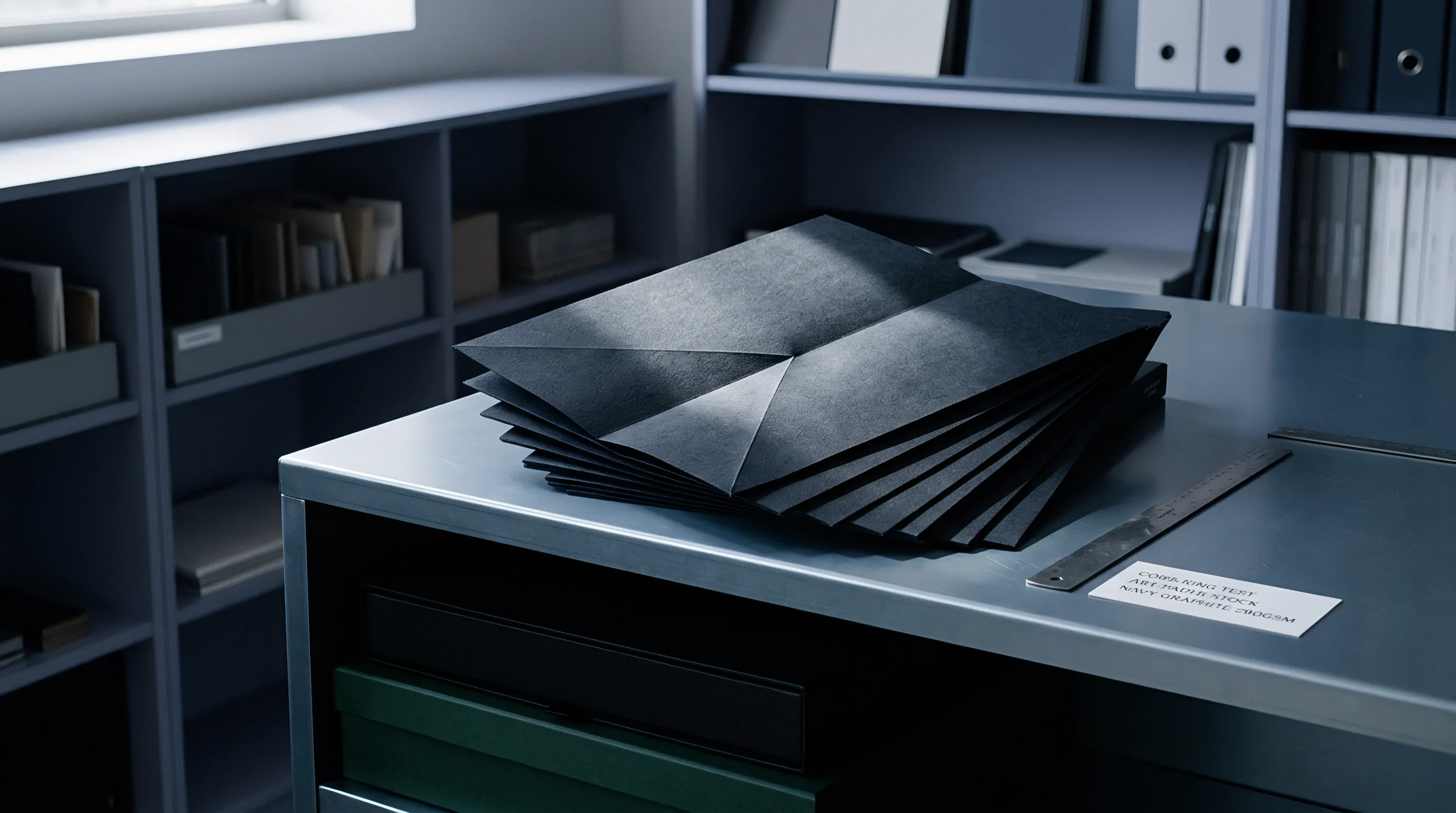
Selecting secondary coatings demands matching polymer mechanics to the physical flexural strain imposed by folding operations.
- Polypropylene Lamination provides flexible tensile elongation that spans creased score lines without optical micro-fracturing.
- Aqueous Coating Formulations yield moderate elastic recovery, preventing fine cracking when plasticizer concentrations remain above four percent.
- Radcure UV Coatings form dense cross-linked networks that crack along high-strain crease folds unless modified with flexible acrylated oligomers.
- Hot Foil Stamping exhibits localized foil flaking across score beads when sizing resin lacks thermal compliance under mechanical shear.
Ignoring varnish elasticity across score lines leads to mass rejection of finished cartons at high-speed filling plants.
Audit
Reliable production control depends on tight environmental regulation and disciplined press-side checks. Ambient moisture shifts alter paperboard compliance quickly. Moving from fifty percent to sixty-five percent relative humidity adds roughly two percent moisture to the board, softening core fibers and lowering crease stiffness ratios by as much as fifteen percent.
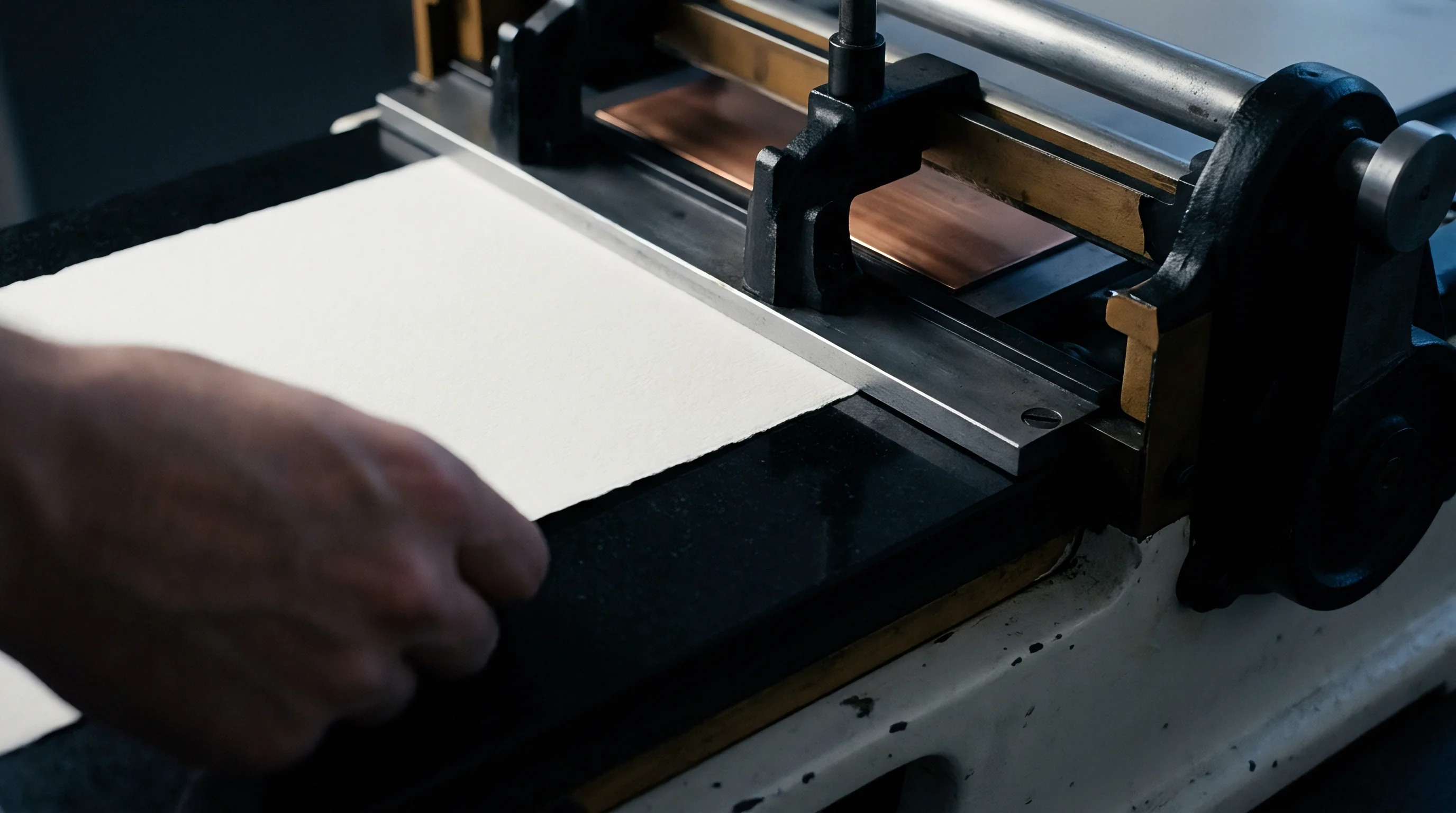
Press operators verify physical score quality on initial die-cut sheets before signing off on full runs. Inspectors check bead symmetry, impression depth, and surface appearance under standardized lighting using hand magnifiers.
Moisture content shifts of two percent alter board bending stiffness enough to disrupt automatic cartooning lines.
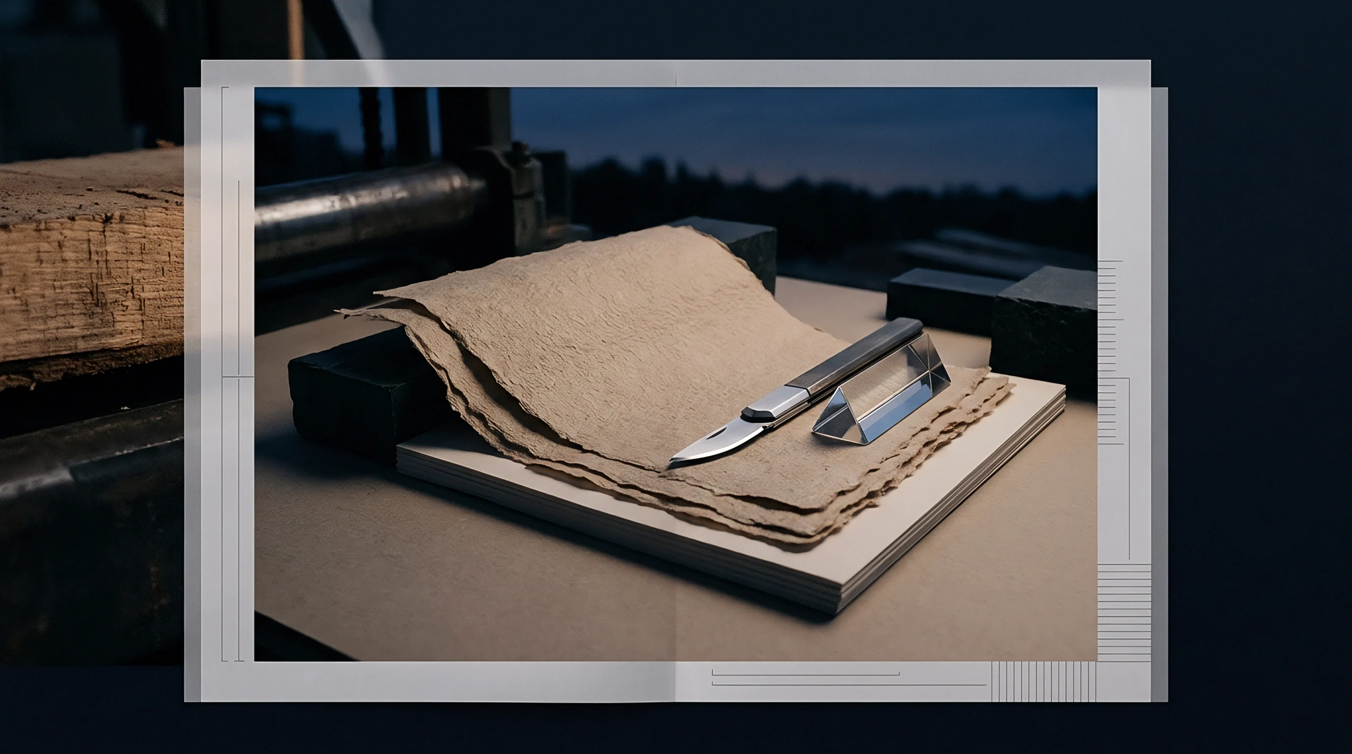
Routine audits also rely on cross-sectional examination. Operators slice across the crease bead with a fresh razor blade to inspect ply behavior under magnification. This cross-section shows whether internal delamination spread evenly across the core or collapsed into a single localized fracture.
Balanced ply shear across the groove width is essential for straight panel tracking on packaging lines.
High-speed packaging equipment exposes scoring errors immediately. As blanks pass through vacuum pickers and high-speed folding swords, uneven crease stiffness causes panel twist, skewed glue seams, and jams on cartoners running at four hundred cartons per minute. Standardized physical checks remain the primary safeguard ensuring converted board meets the mechanical demands of the packing hall.
The precise interaction between bio-based barrier coatings and recycled fibre shear failure during sub-zero crease folding remains an open area of inquiry.