Substrate Holdout and Pinhole Formation in Inline Flexographic Coating
Substrate holdout and pinhole control require matching anilox coat weight delivery to sheet absorbency while regulating dynamic wetting and surface skinning.
Surface
Substrate Absorbency and Capillary Penetration Mechanics
Paperboard top layers consist of cellulose fiber networks interspersed with mineral pigments, latex binders, and sizing agents. When liquid flexographic formulations hit this porous structure, capillary forces pull the water or solvent carrier into the void fraction. Capillary rise follows Washburn kinetics, where liquid penetration depth scales with the square root of time, liquid surface tension, pore radius, and the cosine of the contact angle, divided by fluid viscosity.
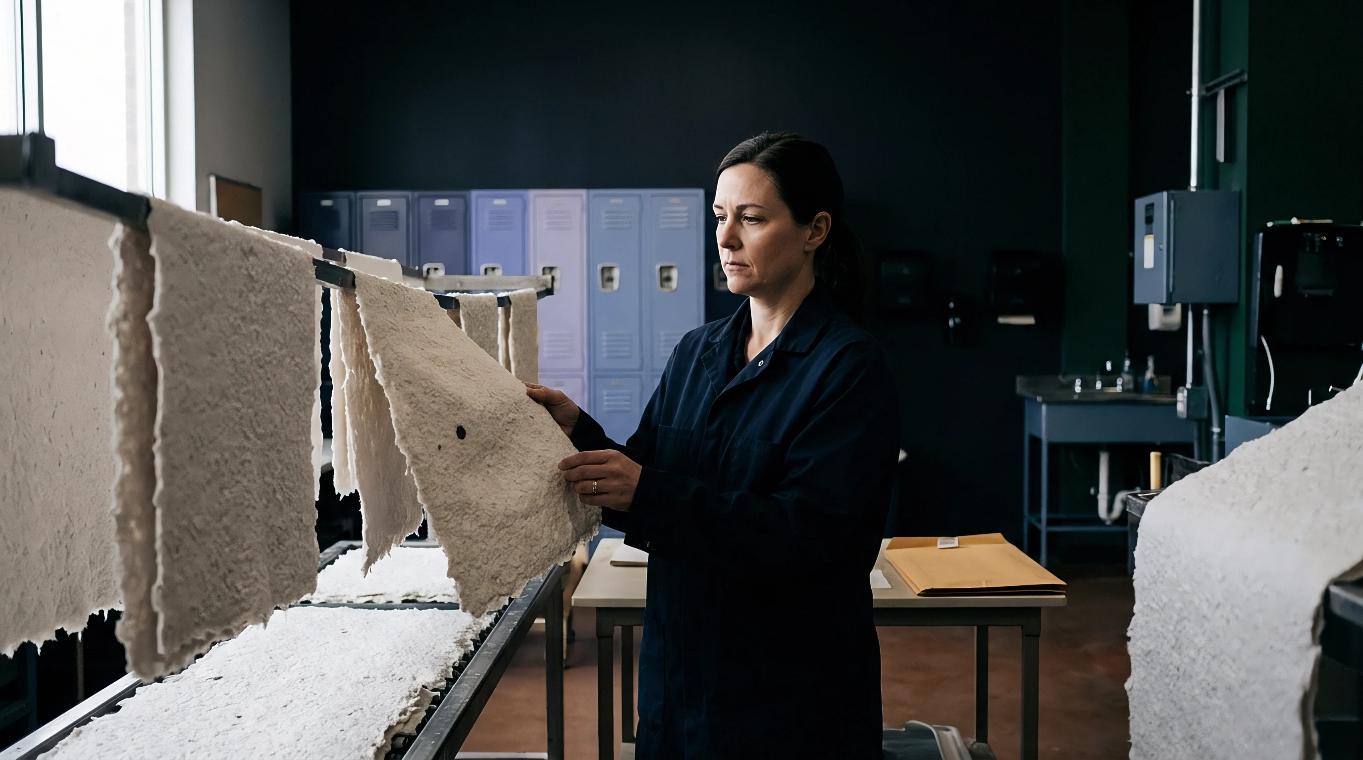
Uncoated or lightly sized paperboard grades exert high capillary suction, pulling liquid vehicle out of the applied fluid film before leveling can finish.
Liquid absorption reduces film thickness. As water or solvent drains into the sheet, the remaining coating layer experiences a rapid rise in solids percentage. This immobilizes the polymer binder before hydrodynamic leveling flattens the surface topography left by the flexographic metering roll.
High-porosity base stocks absorb liquid vehicle within five to fifteen milliseconds of application. That window falls well inside the forty to eighty milliseconds required for a water-based fluid to level across a thirty-micrometer peak-to-valley substrate roughness profile at line speeds exceeding one hundred fifty meters per minute.
Sizing degree directly governs fluid holdout. Cobb values measured over sixty seconds under ISO 535 reflect overall water absorption, but short-dwell absorption under fifty milliseconds dictates inline holdout. Sizing agents like alkenyl succinic anhydride or alkyl ketene dimer alter fiber wall energy, converting hydrophilic cellulose into hydrophobic surfaces.
Inadequate internal or surface sizing allows liquid strike-through, depriving the wet layer of sufficient volume to form a continuous film.
A sixty-second Cobb value above thirty-five grams per square meter forces liquid varnish absorption prior to film leveling at web speeds exceeding two hundred meters per minute.
Base Topography and Sheffield Roughness Dynamics
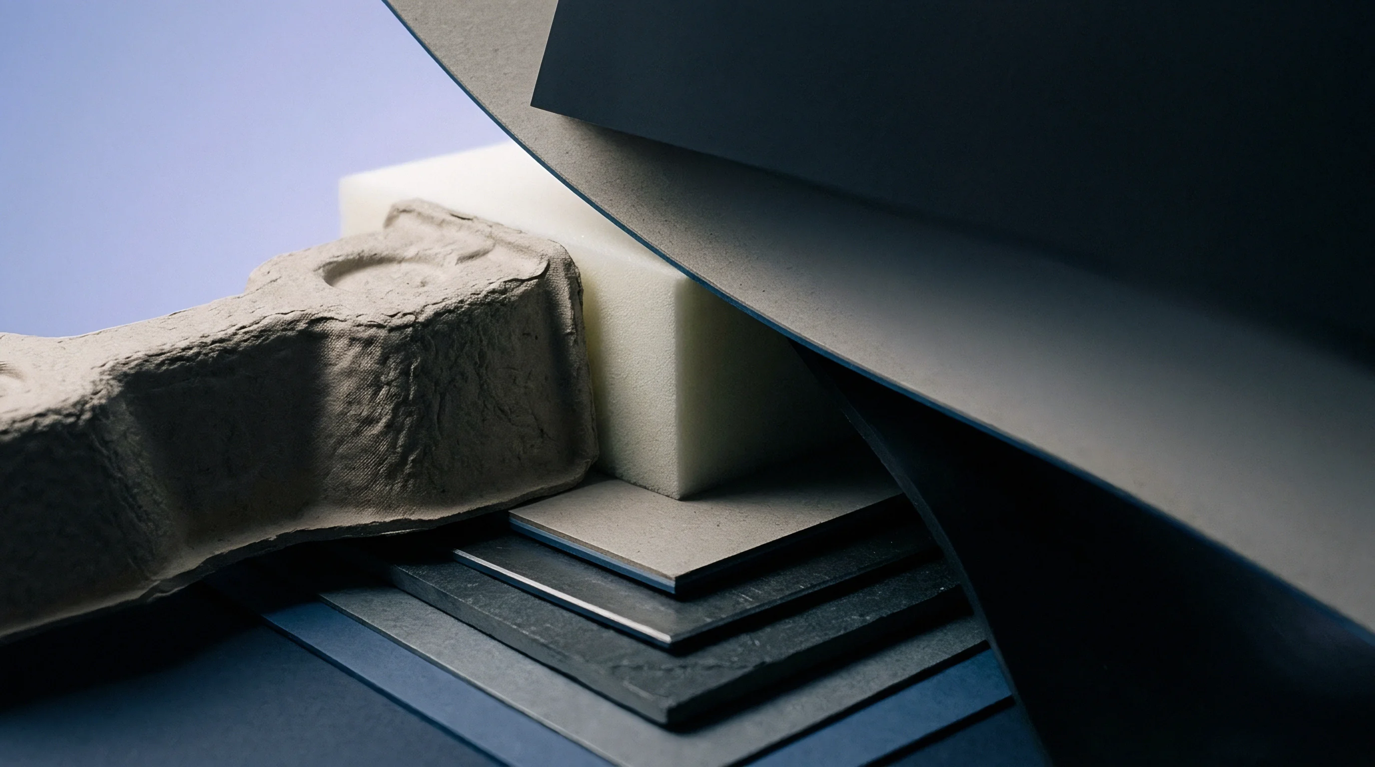
Substrate peak-to-valley height dictates the wet film thickness needed to cover surface features completely. Base papers with a Sheffield roughness rating above one hundred fifty units present distinct hills and valleys. Flexographic blade doctoring and anilox transfer deposit a uniform volumetric sheet of liquid, but that liquid redistributes across non-uniform geometry.
Fluid flows off raised high points into low valleys under capillary and gravitational pressure, thinning the wet film over fiber peaks.
Top-coat holdout fails when local film thickness falls below the local peak-to-valley roughness amplitude. Over raised fibers, thinned wet film ruptures under surface tension forces, exposing raw substrate. Mechanical calendering compresses paperboard sheet structure, reducing void volume and smoothing surface topography.
Double-coated virgin fiber paperboards provide low porosity alongside Bendtsen roughness values under fifty milliliters per minute, securing liquid holdout without excessive coat weight applications.
- High Porosity Base Stock Absorbs liquid vehicle rapidly, causing premature immobilization of the coating matrix before surface leveling flattens cell impression patterns.
- Low Internal Sizing Level Permits fluid penetration into the internal Z-directional fiber structure, draining volume from the top wet layer and producing thin spots.
- Elevated Surface Roughness Creates localized high points where wet film thickness thins below critical continuity thresholds, forming bare spots and micro-voids.
- Uneven Fiber Distribution Generates localized density variations across the web, causing erratic absorption rates and uneven film formation across the sheet width.
Recycled fiber grades complicate holdout due to inconsistent density distribution and variable pore size geometry. Starch applied at the size press seals surface pores, increasing liquid resistance. Mechanical treatment during stock preparation alters fiber length distribution, changing capillary suction characteristics across the web cross-direction.
Smooth, dense, highly sized substrates maintain liquid volume on the surface long enough for viscosity and surface tension forces to form a uniform coating layer.
| Paperboard Grade Type | Cobb 60s Value (g/m²) | Sheffield Roughness (SU) | Base Porosity (mL/min) | Holdout Performance |
|---|---|---|---|---|
| 22 – 28 | 40 – 60 | 10 – 25 | Excellent | |
| 28 – 34 | 65 – 90 | 30 – 55 | Moderate | |
| 25 – 30 | 50 – 75 | 15 – 35 | Good | |
| 35 – 48 | 110 – 160 | 70 – 130 | Poor |
Measuring dynamic fluid contact angles clarifies holdout behavior under high-speed flexographic application conditions. Droplet contact angles dropping below thirty degrees in less than one hundred milliseconds signal excessive sheet absorbency. High-speed cameras paired with automated drop shape analyzers track fluid drop volume depletion over time, isolating capillary absorption from lateral spreading.
Matching coating formulation solids content to base sheet absorbency characteristics prevents fluid drainage while ensuring adequate film leveling prior to the dryer entrance.

Cell
Metering Roll Volume and Screen Count Mechanics
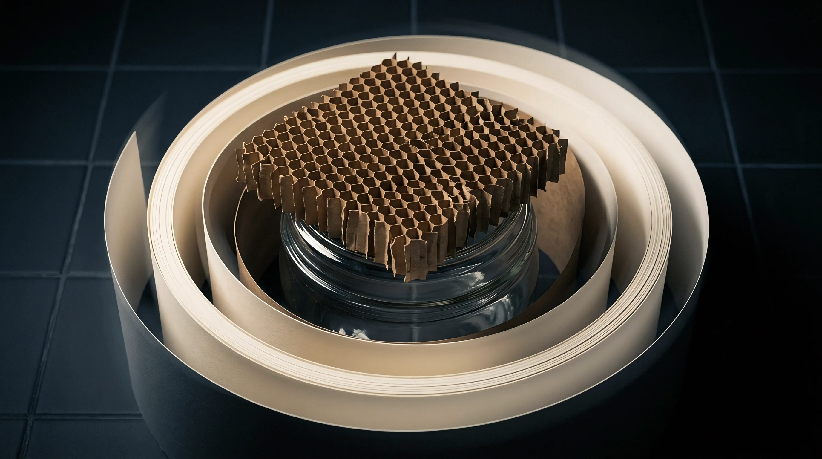
Anilox engraving geometry governs liquid volume delivery to the flexographic plate or direct-application roller. Laser-engraved ceramic rolls feature hexagonal cell geometry with sixty-degree alignment, tri-helical bands, or channel-based patterns. Screen counts ranging from one hundred to four hundred lines per inch define cell opening diameter and depth.
Deep cells with high depth-to-opening ratios above thirty percent suffer from incomplete fluid discharge, leaving dry deposit buildup inside the cell base over extended production shifts.
Fluid volume transferred from roll to plate ranges between twenty-five and forty-five percent of total engraved cell volume. High line-count engraved rolls with lower carrying capacity deposit thin wet films that dry rapidly but lack sufficient mass to bridge base paper topography. Low line-count rolls with higher carrying capacity transfer thick wet layers, but excessive liquid delivery risks fluid pooling, hydraulic air entrapment, and severe edge-beading along print borders.
Doctor blade configuration maintains precise volumetric control across the meter roll surface. Reverse-angle chamber doctor blade systems maintain constant hydraulic pressure against the rotating surface, preventing ambient air ingress into fluid cells. Blade tip wear or incorrect contact angles alter wiped fluid profile thickness, creating localized volume variations that cause coating film rupture downstream.
Shear Rate and Viscosity Behavior in Application Nips
Flexographic fluid delivery subjects wet formulations to shear rates exceeding one hundred thousand reciprocal seconds within the metering nip. Water-based barrier varnishes exhibit non-Newtonian shear-thinning pseudoplastic rheology. Viscosity drops sharply during high-shear transfer through the roll nip, allowing rapid liquid spreading across the substrate surface upon exit.
- Verify anilox roll cell volume using interferometric optical measurement before mounting the cylinder into the press frame.
- Set chamber doctor blade end-seals and blade contact angle to twenty-eight degrees relative to the cylinder tangent line.
- Circulate fluid formulation through the supply loop until temperature stabilizes at twenty-three degrees Celsius and viscosity reaches target cup seconds.
- Engage roller impression against the backing cylinder to establish a nip footprint width of three point five millimeters across the entire face width.
- Accelerate web speed to target production velocity while monitoring dynamic liquid transfer uniformity across the printed sheet surface.
Extensional viscosity controls liquid filament splitting as the plate separates from the moving paperboard web. High extensional viscosity creates long fluid threads that break unevenly, causing droplet splashback, misting, and surface void formation. Fluid formulations containing high molecular weight polymers demonstrate excessive extensional resistance, forming surface peaks that fail to level before entering thermal drying zones.
Liquid viscosity management requires continuous monitoring of shear rate response and thermal equilibrium during press runs. Friction generated within high-speed blade chambers elevates fluid temperature, driving water or solvent evaporation and increasing bulk viscosity over time. Automated viscosity control systems inject solvent or water to balance formulation solids content, preventing film thickness drift and associated coating defects across extended shifts.
Micro-voiding can stem from raw paperboard variation or shear degradation in the delivery pan.

Wetting
Dynamic Surface Tension and Spreading Thermodynamics
Wetting dynamics depend on the interface between liquid formulation surface tension and substrate surface energy. Static surface tension measurements obtained via the Wilhelmy plate method fail to capture fluid behavior at high application speeds. Dynamic surface tension measured at surface ages under ten milliseconds reflects real press conditions, where freshly exposed fluid interfaces encounter raw paperboard surfaces within milliseconds.
Spreading coefficients must remain positive to achieve complete liquid film distribution across the substrate. A positive spreading coefficient occurs when substrate surface energy exceeds the sum of liquid surface tension and interfacial energy between sheet and coating. Water-based coatings typically exhibit static surface tension values between thirty and forty-five millinewtons per meter.
Uncoated paperboard substrates present surface energy values ranging from thirty-two to forty-eight millinewtons per meter depending on sizing and synthetic additive content.
Compliance with TAPPI standard T 559 grease resistance specifications requires a continuous film structure free of micro-voids across the entire printed area.
Surfactant additive package selection dictates dynamic surface tension reduction rates. Silicone fluorosurfactants and ethoxylated acetylenic diols migrate rapidly to freshly created liquid interfaces, lowering surface tension during high-speed transfer. Slow-migrating surfactants leave surface tension high during the initial millisecond contact window, causing liquid reticulation, droplet bead-up, and incomplete wetting over low-energy substrate regions.

Dewetting Forces and Film Leveling Windows
Dewetting occurs when an applied liquid layer contracts into discrete droplets to minimize interfacial energy. Substrate contamination, such as silicone oil droplets, wax migration, or anti-setoff spray powder, creates localized low-surface-energy spots. When local substrate surface energy drops below coating surface tension, liquid pulls back from the contaminated region, forming circular pinholes known as fisheyes.
Leveling of wet surface irregularities follows the Orchard model, where driven leveling force scales with surface tension and wet film thickness cubed, while inverse resistance scales with fluid viscosity and wavelength quadrupled. High coating viscosity retards leveling speed, whereas low viscosity speeds leveling but increases risk of fluid absorption into porous paperboard substrates. The operational leveling window opens the moment liquid leaves the transfer nip and closes when drying increases fluid viscosity past the gelation threshold.

Can Dynamic Surface Tension Predict High Speed Pinholing?
Bubbles formed during dynamic surface tension testing provide insight into surfactant migration rates under millisecond contact conditions. Rapid surface tension depression prevents fluid film rupture over substrate surface variations. Test instruments measuring maximum bubble pressure monitor dynamic surface tension changes across surface ages from one millisecond to one thousand milliseconds, allowing chemical formulators to fine-tune wetting speed to match press line velocities.
Inadequate surfactant response times lead to dewetting craters and thin spots along high-speed flexographic lines. Adding excessive surfactant, however, depresses surface tension too far, inducing foam generation and inter-coat adhesion failure during multi-pass converting. Optimizing surfactant concentrations balances initial spreading kinetics against anti-foam requirements across specified line speeds.
Whether surfactant migration during rapid drying alters non-polar barrier crosslinking remains an open operational question across high-speed converting lines.

Pit
Air Entrainment, Micro-Foaming, and Vent Collapse
Air ingress occurs continuously within flexographic fluid delivery loops during high-speed rotation. Recirculation pumps, open return pans, and doctor blade chamber seals inject ambient air into liquid formulations, creating stable dispersion bubbles. Micro-foam bubbles under fifty micrometers in diameter remain suspended in high-viscosity coatings, escaping mechanical entrainment filters and passing directly onto the anilox roller.
Suspended air bubbles transferred to the substrate create micro-voids upon drying. As wet coating layers move into thermal drying zones, entrained air bubbles expand rapidly due to heat exposure. The thin liquid envelope surrounding the expanding gas bubble thins until it ruptures, leaving a crater-like depression or complete void through to the paperboard base.
Fast drying locks these ruptured bubble structures into place before fluid leveling can fill the void.
- Excessive Pump Agitation Introduces high volumes of ambient air into fluid return lines, forming fine micro-foam suspensions that resist natural mechanical deaeration.
- Defoamer Exhaustion Occurs when active defoamer compounds emulsify completely or adsorb onto pigment surfaces during prolonged press shear exposure.
- Inadequate Chamber Pressure Allows air passage under doctor blade seals, forming continuous micro-bubble streams within liquid metering cells.
- High Fluid Viscosity Traps small air bubbles within bulk formulation mass, preventing buoyant escape prior to web application.
Defoamer chemistry prevents micro-foam stability by destabilizing bubble wall membranes. Hydrophobic silica particles suspended in mineral oil or polyether-modified polysiloxanes enter the air-liquid interface, weakening lamellar liquid films and causing bubble coalescence. Incorrect defoamer selection or overdosing generates oil-spot defects, causing localized dewetting and forming large pinhole craters across the printed sheet surface.
Excessive defoamer addition destabilizes water-based formulations and generates localized dewetting craters.

Solvent Flash Kinetics and Thermal Void Formation
Thermal drying parameters directly influence wet film surface integrity during solvent or water evaporation passes. High velocity hot air dryers and infrared radiation units heat applied wet coatings rapidly to evaporate carrier liquids. Excessive initial drying temperatures induce surface skinning, where top liquid layers form a semi-solid film shell while underlying liquid retains water or solvent volatile compounds.
Trapped volatiles beneath a skinned top surface burst through the solidified film under vapor pressure build-up. This explosive volatile release creates pinhole vents that remain open permanently as coating solids solidify fully. Flashing off volatile components gradually across zoned dryer sections prevents premature surface skinning, maintaining open vapor diffusion pathways until bulk carrier liquid evaporates cleanly.
| Defect Type | Visual Characterization | Microscopic Features | Primary Root Cause |
|---|---|---|---|
| Circular void with raised outer liquid rim | Central low-energy contaminant particle visible | Substrate silicone or wax surface contamination | |
| Irregular crater with thin or absent base layer | Ruptured bubble wall geometry along void rim | Air entrainment and defoamer depletion in coating pan | |
| Small steep-sided hole through film thickness | Vertical channel extending down to substrate base | Premature surface skinning from excessive dryer heat | |
| Non-uniform un-coated region along fiber direction | Exposed paperboard fiber structures without coating matrix | High substrate roughness exceeding wet film thickness |
Hot-air air knife velocities must balance drying rate against wet film displacement forces. Excessive air impingement pressure deforms wet, low-viscosity liquid layers before gelation occurs, creating wave patterns, thick edges, and localized thin spots. Gradient temperature profiles starting low in initial dryer zones and ramping up in late drying zones maintain film structural continuity, suppressing micro-venting and pinhole formation across high-speed runs.
Neglecting temperature-driven viscosity drift guarantees barrier degradation, resulting in rejected rolls and uncompensated converting downtime.


Barrier
Pinhole Verification and Chemical Resistance Testing
Functional barrier coatings intended for food packaging applications require complete film continuity to block grease, water, and volatile organic compounds. Standardized testing protocols assess substrate holdout and pinpoint structural micro-voids across converting sheets. Methylene blue stain testing under EN 13676 applies alcohol-based dye solutions to coated paperboard surfaces for specified duration intervals, highlighting pinholes as distinct blue spots where dye penetrates to underlying fibers.
Turpentine testing under TAPPI T 454 measures grease resistance by placing silica sand saturated with colored turpentine onto coated surfaces. The time required for turpentine to penetrate through coating micro-voids to stain underlying white backing paper defines failure thresholds. Grease resistance testing via TAPPI T 559 KIT tests uses mixtures of castor oil, toluene, and heptane in twelve standardized ratio solutions.
Higher KIT numbers reflect superior grease barrier performance, but discrete pinholes cause localized KIT failure regardless of average coat weight performance.
Pinhole frequency increases exponentially when wet film thickness falls below the maximum peak-to-valley roughness depth of the base stock.
Water vapor transmission rate testing under ASTM E96 measures gravimetric moisture flow through barrier layers under controlled temperature and relative humidity gradient conditions. Pinholes act as direct vapor diffusion channels, elevating measured transmission rates far above theoretical polymer permeability values. Helium leak detection and high-resolution optical image analysis quantify microscopic pore density per square meter, enabling precise quality grading of production runs.
Quality Compliance and Specification Frameworks
Acceptance specifications set strict defect count thresholds based on intended packaging applications. High-barrier packaging for oil-rich foods permits zero pinholes under standard stain testing across representative sample sheets. Decorative overprint varnishes tolerate low pinhole densities, provided visual gloss and rub resistance criteria meet brand owner expectations.
- Sample Selection Protocol Harvests ten full-width sheet samples across three production roll positions to evaluate cross-direction continuity.
- Stain Solution Preparation Calibrates methylene blue dye concentration in ethanol solution to ensure consistent fiber staining contrast.
- Dwell Time Control Enforces exact two-minute contact periods for chemical indicator exposure prior to solvent wipe down and optical inspection.
- Automated Defect Counting Employs calibrated vision systems to count and categorize defect diameters down to ten micrometers resolution.
Statistical process control charts track pinhole density metrics per thousand square meters during long converting runs. Sudden spikes in defect counts signal mechanical component degradation, such as anilox clogging, doctor blade notch formation, or thermal dryer sensor drift. Immediate press adjustments restore operating parameters within specified statistical capability bounds before non-compliant packaging material enters finished goods inventory.
Inserting a maximum defect density threshold of two pinholes per square meter under ISO 16532 testing shifts financial liability for grease strike-through directly to the coating vendor.
Duty
Coat Weight Optimization and Commercial Yield Economics
Applying barrier finishes or decorative varnishes adds direct material expense to converted packaging orders. Water-based barrier formulations cost between two euro fifty and five euro fifty per wet kilogram depending on binder resin polymer chemistry and specialized additive packages. Dry coat weights applied inline range from three to twelve grams per square meter depending on base sheet absorbency and target barrier performance levels.
Increasing applied coat weight masks base paperboard absorbency defects and covers high roughness peaks, reducing pinhole density across the sheet. Applying excessive wet coating volume, however, increases material cost and creates drying capacity bottlenecks. Press line speeds must drop to accommodate higher water evaporation requirements, increasing machine hourly costs and reducing overall converting floor output capacity.
| Target Dry Coat Weight (g/m²) | Press Speed Capacity (m/min) | Material Cost per 1,000 m² (€) | Pinhole Failure Risk Rate (%) | Total Landed Run Cost per 1,000 m² (€) |
|---|---|---|---|---|
| 250 | 18.40 | 14.5 | 42.50 | |
| 210 | 29.90 | 3.2 | 46.20 | |
| 175 | 39.10 | 0.4 | 51.80 | |
| 135 | 50.60 | 0.1 | 62.10 |
Calculations balancing coat weight expense against converting line speed reveal operational sweet spots. Take an order specifying five thousand square meters of barrier-coated board. Applying six point five grams per square meter balances material outlay against dryer operating speed, maintaining defect rates below commercial rejection limits without forcing severe press speed reductions.
Waste Arithmetic and Multi-Pass Cost Realities
Pinhole failure detected after full print runs results in complete lot rejection, incurring heavy financial losses across paperboard, ink, labor, and delivery scheduling penalties. Offline double-pass coating operations eliminate inline dryer speed bottlenecks but introduce secondary set-up charges, additional make-ready waste, and extended production lead times. A second machine pass adds between eight and fifteen percent to total packaging job production cost.
Inline flexographic coating optimization eliminates secondary handling charges and cuts job turnaround times significantly. Running inline requires absolute process control over base sheet absorbency, anilox volume delivery, dynamic wetting surface chemistry, and thermal flash drying schedules. Eliminating pinhole defects during inline processing secures certified barrier performance, protects converting gross margins, and eliminates costly client claims on high-value packaging runs.
Balancing coat weight against line speed yields consistent film integrity only when substrate smoothness matches fluid leveling time.