Doctor Blade Contact Hydrodynamics in High Speed Flexographic Printing
High-speed flexographic doctor blade metering balances mechanical clamping pressure against fluid hydrodynamic lift to maintain stable boundary contact.
Contact
Boundary Lubrication at Line Speeds
Anilox roll surfaces rotating at web speeds above 400 metres per minute generate immense hydrodynamic lift within the ink boundary layer. The mechanical metering system counters this fluid uplift by establishing a controlled contact zone across the microscopic land areas of the ceramic sleeve. When an operator tensions a chambered doctor blade system to a nominal load of 1.5 to 2.5 bar pneumatically, the actual contact pressure exerted across a 100-micrometre blade tip lands in the range of 10 to 35 megapascals.
This pressure forces the metering edge through the bulk ink film into a regime dominated by elastohydrodynamic lubrication and boundary contact. Fluid viscosity, roll roughness, contact angle, and blade elasticity dictate whether the tip skims across an unbroken liquid film or planes the excess ink directly from the cell plateaux.
Mechanical deflection alters the geometric engagement angle continuously during press acceleration. A steel strip clamped at a nominal angle of 30 degrees to the roll tangent bends under drag forces and hydraulic thrust, flattening the effective tip profile to 20 degrees or less. This deflection increases the fluid wedge beneath the working edge, converting tangential shear into vertical separation force.
The fluid mechanics within this narrow interface govern printing consistency on high-speed corrugated, cartonboard, and flexible packaging lines.
Hydrodynamic lift forces at 500 metres per minute reduce effective mechanical clamping pressure at the ceramic roll surface by up to forty percent.
Boundary contact requires physical interaction between the metering strip and the chromium oxide roll land areas. Fluid dynamics literature defines the non-dimensional Sommerfeld number to chart this operational state:
S = (η × U) / (P × L)
The variable η represents dynamic ink viscosity in pascal-seconds, U denotes web speed in metres per second, P signifies blade contact pressure per unit length, and L represents the contact land width. In water-based and solvent-based flexographic setups running at 8 to 10 metres per second, dynamic ink viscosity shifts rapidly under high shear. As shear rates inside the cell-edge gap surpass 100,000 reciprocal seconds, pseudoplastic ink vehicles thin out.
This shear thinning helps maintain boundary contact, yet residual viscoelastic normal stresses resist edge entry into the microscopic valleys of the roll.
Mechanical Force Balance along the Anilox Interface
The equilibrium established at the roll face involves three distinct forces acting upon the blade edge. The downward mechanical clamping force applied via pneumatic pistons or mechanical screws pushes the blade inward. Opposing this clamping force is the hydrodynamic uplift force generated by the fluid entry wedge, alongside the mechanical reaction force exerted by the hard ceramic roll lands.
Stable metering demands that the mechanical downward force consistently exceeds the fluid lift force across the roll face.
Uneven pressure profiles across the web width introduce severe fluid film variations. If pneumatic cylinder pressure falls below 1.2 bar on wide-web presses exceeding 1.6 metres in width, hydrodynamic fluid wedge pressure pushes the blade away from the roll face. This separation generates ink spitting, streaking, and unwanted ink film passage over the cell boundaries.
Excessive loading pressure applied to suppress hydrodynamic lift accelerates ceramic land abrasion, micro-chipping, and premature tip failure.
The relationship between press velocity, hydrodynamic wedge pressure, and physical blade contact governs ink laydown on paperboard substrates. High-speed fluid metering balances hydrodynamic force control with premature wear suppression.
Viscosity
Rheological Behavior under High Shear Rates
Flexographic inks exhibit severe pseudoplasticity during high-speed metering. At quiescent rest inside the ink reservoir or supply bucket, ink viscosity ranges from 50 to 150 millipascal-seconds, measured with a Brookfield rotational viscometer at 25 degrees Celsius. When the rotating anilox roll drags this fluid beneath the doctor blade contact edge, shear rates escalate past 1,000,000 reciprocal seconds.
Viscosity plummets to 5 to 15 millipascal-seconds under this intense localized shearing field. This drop controls the fluid hydrodynamic pressure profile developed at the entry convergent zone.
Viscoelastic formulations containing high-molecular-weight acrylic resins resist instantaneous deformation. When long polymer chains stretch within the converging fluid wedge, they create extensional viscosity stresses that exceed purely shear-driven values. These extensional forces act as a hydraulic spring beneath the blade heel, exerting a lift force that simple Newtonian fluid equations fail to predict.
Formulations running high resin solids generate strong normal forces at speeds beyond 450 metres per minute, requiring operators to raise pneumatic blade pressure to avoid fluid leakage across roll lands.
| Ink Chemistry Type | Base Viscosity (mPa·s, 23°C) | High-Shear Viscosity (10⁶ s⁻¹) | Hydrodynamic Lift Force (N/m) | Critical Float Velocity (m/min) |
|---|---|---|---|---|
| Water-based Flexo Emulsion | 120 | 12 | 85 | 420 |
| Solvent Nitrocellulose System | 45 | 6 | 42 | 580 |
| Radiation-Cured UV Acrylate | 450 | 65 | 310 | 210 |
| Water-based Barrier Varnish | 220 | 28 | 160 | 310 |
Extensional Stress within the Convergent Wedge
Extensional viscosity generates distinct operational issues during aqueous coating operations on heavy virgin fiberboard. As aqueous acrylic formulations enter the narrowing clearance between the metering blade and the rotating roll, polymers experience rapid uniaxial stretching. The entrance angle creates an acceleration zone where fluid elements deform in milliseconds.
This deformation triggers a sharp rise in extensional resistance, elevating fluid hydrodynamic wedge pressure far above standard shear-thinning estimates.
Solvent systems exhibit lower extensional stress profiles than water-based acrylic polymers. Lower extensional stress reduces the hydrodynamic fluid wedge pressure at equivalent press run speeds. Consequently, solvent presses maintain effective mechanical boundary contact at speeds up to 600 metres per minute without needing high blade pressures.
In contrast, water-based systems on white-lined chipboard lines run into floating issues at lower velocity thresholds unless resin molecular weight is tightly controlled.
Ink vehicle formulation changes shift the operational hydrodynamic boundary. Adjusting resin ratios or water addition without monitoring shear viscosity alters metering consistency, creating uncontrolled ink transfer variations onto the printing plate.
Wedge
Geometry of the Converging Fluid Zone
Fluid dynamics between a moving curved cylinder and a flat cantilevered plate creates a lubrication wedge. Ink enters this narrowing zone, building dynamic pressure that peaks immediately upstream of the physical contact line. The Reynolds lubrication equation describes this dynamic pressure profile:
d/dx = 6 × U × (dh/dx)
The variable h represents ink film thickness as a function of position x, η denotes shear-dependent dynamic viscosity, and U represents anilox surface speed. As film thickness h narrows toward zero near the contact line, pressure gradient dp/dx rises steeply. This produces a pressure spike capable of lifting the metallic blade tip away from the roll face.
Blade entry angle relative to the roll surface establishes the geometric profile of this converging fluid zone. A steep contact angle of 35 to 40 degrees limits the spatial extent of the convergent wedge, shortening the hydrodynamic pressure profile. Conversely, shallow angles below 25 degrees extend the entry ramp, providing a longer runway for fluid pressurization.
This extended ramp magnifies total hydrodynamic lift force, forcing the blade upward and leaving excess ink on roll lands.
A contact angle decrease from thirty-five degrees down to twenty-two degrees doubles the hydrodynamic uplift force acting on the blade holder assembly.
Reverse-angle doctor blade configurations eliminate the positive pumping actions typical of forward-wipe geometries. When the anilox rotates into the reverse blade edge, the incoming fluid momentum strikes the blade backing, generating downward shearing vectors. If clamping rigidity is insufficient, incoming hydrodynamic shock waves bend the edge backward, inducing high-frequency mechanical chattering.

Fluid Pressure Distribution Profiles
The pressure field within the converging ink meniscus acts over a contact band measuring 50 to 150 micrometres wide. Numerical integrations of the Reynolds equation across this micro-zone reveal peak fluid pressures reaching 3 to 8 megapascals at web speeds of 500 metres per minute. This fluid pressure field approaches the mechanical yield stress of worn doctor blade steel.
Hydrodynamic forces also interact with ink cell geometry. Anilox engraving patterns influence fluid pressure generation upstream of the contact tip. Conventional 60-degree hex cells retain ink internally, while continuous channel designs provide relief pathways for trapped ink films.
These geometric channels disrupt hydrodynamic pressure peaks, altering the balance between boundary contact and fluid lubrication.
Blade holders must balance structural stiffness with tip conformability. High hydraulic forces within the fluid wedge bend unreinforced blades, altering the contact footprint and generating print defects across wide webs.
Wear
Micro-Mechanics of Tip Degradation
Continuous contact against plasma-sprayed ceramic anilox rolls subjects doctor blades to severe mechanical and chemical wear. Industrial anilox rolls utilize chromium oxide ceramic coatings featuring surface hardness ratings between 1,200 and 1,400 Vickers. Standard carbon steel doctor blades offer hardness ratings of roughly 550 to 600 Vickers.
This large hardness differential creates an abrasive interface where hard roll surfaces erode softer steel edges during boundary contact.
Abrasive wear rates accelerate whenever titanium dioxide pigments or mineral coatings contaminate the circulating ink. Titanium dioxide particles present in white ink formulations possess a Mohs hardness of 6.0 to 6.5, matching or exceeding standard blade steels. As these hard particles wedge beneath the contact edge, they carve micro-grooves into the blade land.
This abrasive scouring causes mechanical grooving, localized fluid bypass, and visible print streaks along the paper web.
Mechanical wear patterns typically develop through three distinct physical stages:
- Honing phase establishes initial conformability as raw steel edges lap against the rotating ceramic cylinder to remove manufacturing burrs.
- Equilibrium abrasive wear maintains a stable tip land thickness between 80 and 150 micrometres during prolonged steady-state metering operations.
- Heel sliver formation develops when mechanical pressure bends fatigued steel backwards, creating micro-burrs that shed into ink chambers and score roll faces.
Chemical and Thermal Breakdown Modes
Aqueous ink chemistries running at basic pH levels accelerate blade degradation through combined tribo-chemical wear. Most water-based flexographic packaging inks operate at a pH range of 8.2 to 9.4, stabilized using volatile amines like dimethylethanolamine or ammonia. At elevated interface temperatures, water and basic amines break down the passive oxide film on carbon steel doctor blades.
This chemical stripping exposes bare metal, promoting rapid corrosive wear.
Frictional heat generated within the lubricated contact zone raises edge temperatures significantly. Under high speed and heavy loading, interfacial temperatures surpass 90 degrees Celsius. This localized heating reduces fluid viscosity, degrades boundary lubrication films, and triggers thermal softening in polymer or low-alloy blades.
These microstructural changes accelerate mechanical wear and edge deformation across continuous press runs.
Premature blade wear destroys mechanical metering precision, degrading print quality and driving up operating costs across packaging plants. Controlling friction, loading forces, and ink chemistry preserves blade integrity and maintains predictable color laydown.

Dynamics
Instabilities Induced by Roll Cavitation and Flow
When microscopic anilox cells pass beneath the doctor blade edge, the rapid transition from high hydrodynamic pressure to atmospheric exit conditions triggers cavitation. As cells emerge from beneath the wiping land, sudden volume expansion creates localized sub-ambient pressure zones within the fluid. Cavitation bubbles nucleate inside liquid menisci, expand, and then collapse violently against cell walls.
This micro-implosion generates shock waves that erode ceramic cell walls and induce mechanical micro-vibrations along the blade tip.
Cavitation-induced pressure spikes propagate backward through the blade body, destabilizing mechanical clamping systems. When these dynamic fluid vibrations match the resonant frequency of the blade holder assembly, the blade chatters. Doctor blade chattering causes rhythmic undulations in blade contact pressure, generating visible cross-direction dark and light bands across the printed substrate.
These chattering marks ruin process print jobs on high-finish coated folding cartonboard.
| Blade Configuration | Tip Thickness (μm) | Contact Width (μm) | Deflection Resistance (N/mm) | Resonant Frequency (Hz) |
|---|---|---|---|---|
| Straight Carbon Steel (0.15 mm) | 150 | 150 | 18.4 | 120 |
| Lamella Profile Carbon Steel | 60 | 65 | 8.2 | 85 |
| Beveled Profile Alloy (15°) | 110 | 115 | 24.6 | 165 |
| Ceramic Coated Matrix Steel | 75 | 80 | 21.8 | 145 |
Cell Emptying Dynamics at Operating Speeds
Ink retention within anilox cells during the wiping stroke depends directly on surface tension and hydrodynamic pressure gradients. As an engraved cell passes beneath the blade tip, fluid along the top cell boundary undergoes severe shearing, while ink inside the cell bottom remains shielded. The ratio between ink boundary layer displacement and total cell volume defines metering efficiency.
High hydrodynamic uplift pulls ink out of cell cavities, creating an over-metered liquid film above the roll face.
Cell volume transfer relies on the capillary number of the ink system:
Ca = (η × U) / γ
The variable γ represents liquid-air surface tension in newtons per metre. High capillary numbers, common at line speeds above 500 metres per minute, signal that viscous hydrodynamic forces dominate surface tension forces. Ink fails to level inside the cells during the microsecond passage under the blade, resulting in uneven cell evacuation and erratic ink transfer onto photopolymer printing plates.
Mismatched blade profiles provoke fluid instabilities within the chamber cavity. Excess turbulence inside closed-chamber systems causes ink foaming, entraining air bubbles that degrade metering quality and disrupt boundary lubrication.

Bleed
Hydrodynamic Leakage across Roll Land Plateaux
Incomplete fluid shearing across anilox land areas produces hydrodynamic bleed, commonly termed trailing-edge spitting. When line speeds accelerate past 450 metres per minute, hydrodynamic wedge pressure can exceed mechanical blade clamp force. The blade tip lifts a few micrometres away from the roll surface, allowing a continuous fluid film to pass over the cell walls.
This escaping ink accumulates on the blade holder exit side until surface tension breaks, spraying droplets onto the web and plate cylinder.
Ink spitting contaminates non-image areas on the moving web, resulting in visual flecking and dirty printing. On coated virgin folding boxboard, these minute ink droplets ruin white backgrounds and lower print contrast. The problem worsens when using low surface energy inks formulated with silicone-based defoamers.
These additives lower ink surface tension, accelerating droplet detachment and uncontrolled splashing across the printing deck.
Chambered doctor blade seals and internal flow geometry influence the onset of hydrodynamic leakage. Defective end seals create localized pressure drops that disrupt fluid recirculation within the closed chamber cavity. Ink pools against the blade clamping edge, increasing fluid residence time and promoting localized overheating and viscosity decay.
Maintaining stable boundary lubrication prevents fluid bleed across high-speed printing decks. Proper blade selection, accurate mechanical alignment, and controlled ink rheology ensure clean wipe performance, eliminating ink misting and preserving print quality at high web speeds.
Balance
Mechanical Rigidity and Dynamic Compliance Trade-Offs
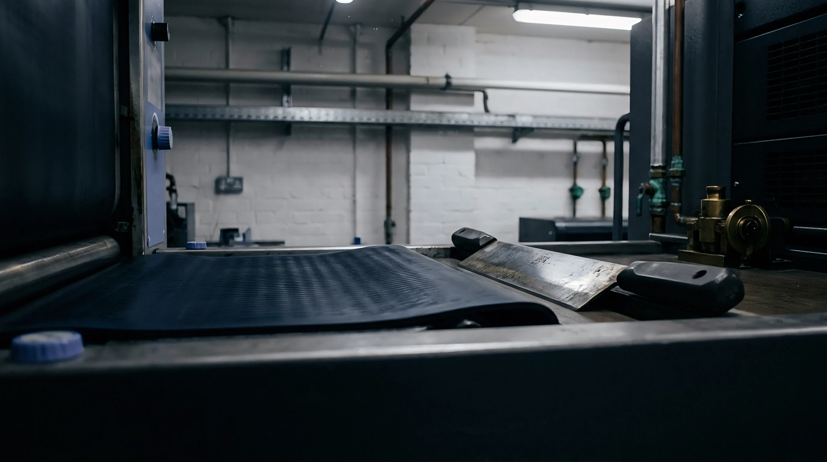
Doctor blade design requires balancing mechanical rigidity against dynamic compliance across the anilox face. Stiff, thick blades resist hydrodynamic lift forces effectively, preventing fluid film bypass at elevated line speeds. However, rigid steel strips conform poorly to microscopic cylinder run-out or roll deflection across wide press frames.
This poor compliance leaves dry streaks in high spots and excess ink films in low depressions, causing color shifts across wide paper webs.
Compliant, thin-profile lamella blades conform closely to minute roll imperfections at modest operating speeds. The reduced tip cross-section maintains a narrow contact area as abrasive wear erodes the steel edge over time. However, low bending stiffness makes thin lamella blades susceptible to hydrodynamic deflection.
Once line speeds surpass 400 metres per minute, fluid wedge forces flex thin lamella tips backward, inducing edge floating, spitting, and poor ink metering.
A doctor blade tip contact width exceeding two hundred micrometres generates excessive hydrodynamic lift that overpowers pneumatic clamping forces at high press speeds.
Selecting blade geometry requires matching press speeds and ink rheology to substrate requirements. Uncoated linerboard printing permits broader metering tolerances, allowing stiff, beveled blade profiles that prioritize long run life. Conversely, high-resolution process printing on smooth coated paperboard requires stepped lamella profiles or micro-beveled alloy strips.
These designs maintain uniform wiping contact without hydroplaning across the rotating roll.
Which Blade Geometry Controls Hydrodynamic Floating?
Beveled doctor blades featuring a 15 to 30-degree ground edge deliver an effective compromise between dynamic stiffness and stable contact width. The thick blade body resists bending under dynamic ink flow, while the precision-ground bevel ensures a compact contact footprint against roll lands. This rigid backing counteracts hydrodynamic fluid wedge pressure, suppressing blade lift across high-speed press runs.
Composite and ceramic-coated doctor blades offer an alternative approach to managing hydrodynamic lift forces. Applying a micro-thin ceramic layer across the blade tip face slows mechanical wear, maintaining contact land dimensions between 80 and 120 micrometres throughout long production runs. Stable contact width prevents gradual increases in effective blade contact area.
This eliminates the drop in contact pressure that causes progressive ink bleeding and hydroplaning on long jobs.
Choosing proper doctor blade geometry and material specification stabilizes ink film metering across wide speed ranges. Optimizing blade stiffness, edge profile, and loading mechanics secures consistent color reproduction, minimizes press stops, and cuts waste on industrial packaging lines.
Press manufacturers continue refining blade clamping systems to balance hydrodynamic lift resistance against roll wear. Operators must set blade deflection angles, chamber pressures, and viscosity targets to maintain reliable boundary lubrication without accelerating roll surface damage.