Dynamic Optical Displacement Calibration Protocols across Folding Boxboard Converting Lines
Dynamic blue-laser displacement calibration eliminates light-penetration drift, securing exact FBB crease metrics and stopping false sheet rejection.
Beam
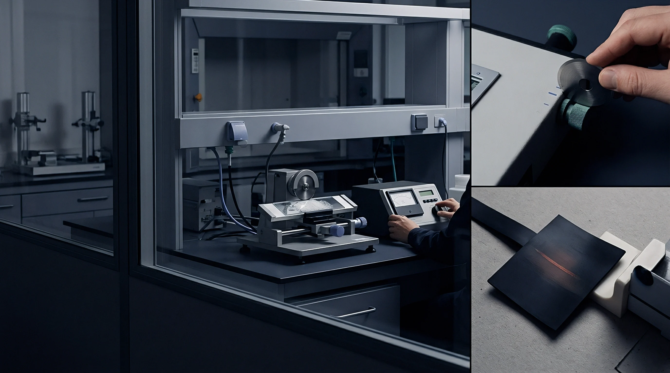
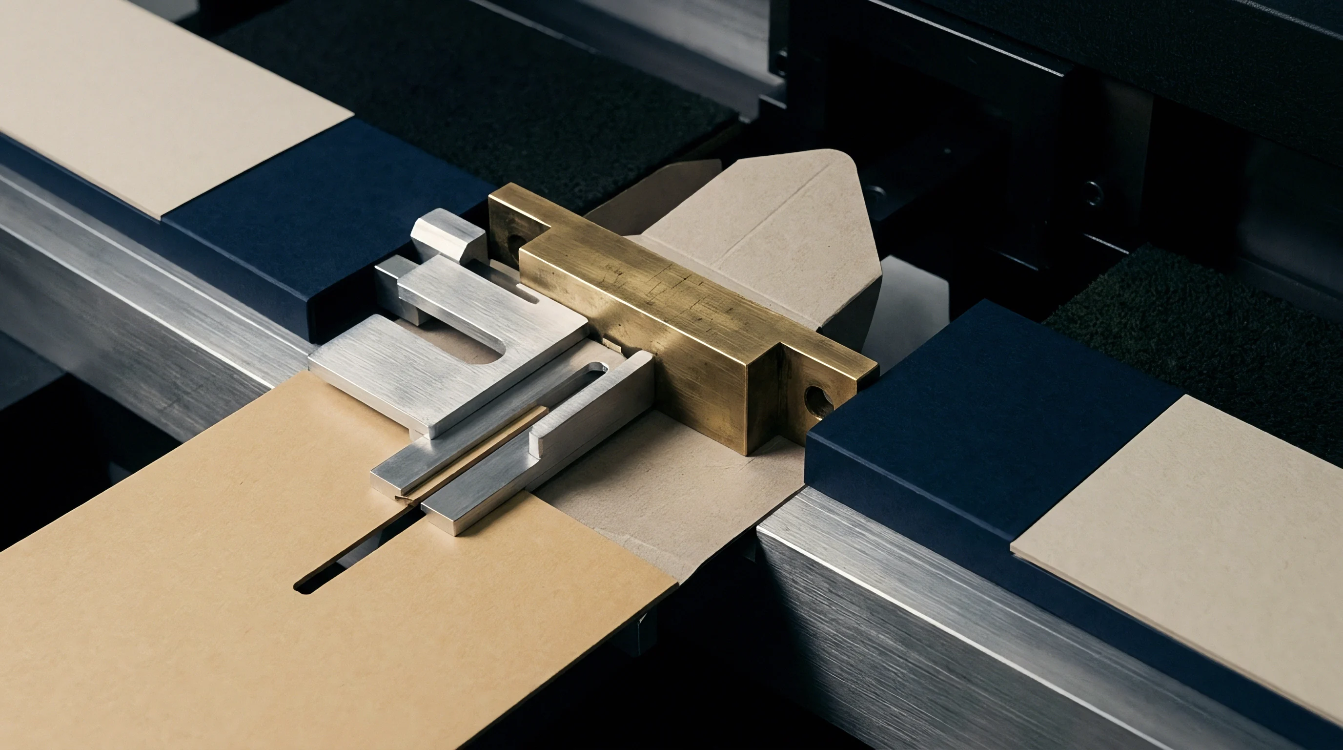
At six hundred meters per minute, high-speed converting lines subject moving folding boxboard to aerodynamic lift, mechanical flutter, and rapid angular displacement. Non-contact optical triangulation sensors capture continuous vertical position variations across the board surface, converting reflected laser light into real-time distance values. Red laser diodes emitting at 658 nanometers penetrate into the top bleached chemical pulp layer of GC1 folding boxboard before scattering back to the linear charge-coupled device array.
In contrast, blue laser emitters at 405 nanometers restrict scattering to the primary pigment coating interface, suppressing measurement noise generated by inner mechanical pulp layers. When converting multi-ply folding boxboard with a grammage of 350 grams per square meter and a nominal caliper of 490 micrometers, variable optical penetration introduces pseudo-displacement errors up to 14 micrometers if sensor calibration relies solely on static matte ceramic standards.
Optical penetration into bleached chemical pulp layers alters triangulation focal distance by 12 to 16 micrometers under standard ISO 187 conditioning at 23 degrees Celsius and 50 percent relative humidity.
Laser triangulation sensors compute distance through geometric projection onto a position-sensitive photodiode array. As folding boxboard passes the sensor head at line speed, surface tilt angles shifting by as little as 1.5 degrees redirect specular reflection away from the receiver aperture. Receiver signal attenuation triggers sensor signal loss or causes false edge detection during crease measurement.
Blue laser diodes mitigate this phenomenon by maintaining a distinct focal spot on highly reflective triple-coated clay surfaces. Selecting the correct light source wavelength stabilizes raw displacement signal noise before digital filtering algorithms process the position array.
| Light Wavelength (nm) | FBB Layer Interaction Zone | Mean Penetration Depth (μm) | Signal Noise Variance (μm) |
|---|---|---|---|
| 405 (Blue-Violet) | Primary Top Coat (Kaolin/TiO2) | 1.8 | 0.35 |
| 520 (Green) | Base Coat and Chemical Top Ply | 6.4 | 1.12 |
| 658 (Red) | Bleached Chemical Pulp Layer | 14.2 | 2.85 |
| 850 (Near Infrared) | Mechanical Groundwood Core | 28.5 | 5.40 |
| Conditioned at ISO 187 (23°C, 50% RH). Substrate evaluated: 300 g/m² GC1 Folding Boxboard with triple blade coating. | |||
When position errors in the optical feedback loop exceed five micrometers, die-cutting control systems miscalculate sheet depth positioning. Miscalibrated optical sensors report fictitious caliper swell, prompting automatic nip adjustments that over-compress the middle groundwood core. Over-compression crushes the internal bulk structure, dropping bending resistance measured under ISO 2493-1 by up to 18 percent and causing box collapse on high-speed side-seam folder-gluers.

Topography
Triple-coated folding boxboard presents a complex surface architecture composed of kaolin clay, calcium carbonate, and synthetic latex binders over an elastomeric fibrous network. Surface micro-roughness measured by Parker Print-Surf at 1.0 megapascal clamping pressure yields values between 0.8 and 1.4 micrometers for premium GC1 grades, whereas recycled GD2 board surfaces often exceed 2.2 micrometers. High gloss specular reflection from supercalendered coatings can blind photodiode arrays, creating localized signal clipping.
Sensor optics must isolate true structural displacement from surface reflectance fluctuations driven by local latex migration and blade coating streaks.
Substrate surface variations disrupt dynamic optical displacement calibration across four distinct physical interaction mechanisms:
- Specular Bleedthrough occurs when high specular gloss saturates individual pixels on the linear photodiode array, displacing the calculated intensity center of mass away from the geometric center of the laser spot.
- Fibre Loft Flutter emerges in un-coated back layers of single-coated boxboard, where loose surface fibres scatter coherent laser light into diffuse interference patterns that broaden the sensor focal spot.
- Pigment Agglomeration Noise generates micro-scale elevation spikes as the optical beam crosses localized clusters of mineral filler, producing high-frequency spatial noise during web movement.
- Moisture Swell Deflection arises when ambient humidity changes alter local sheet thickness, inducing z-axis board plane movement that dynamic sensors must separate from line mechanical vibration.
Transitions across printed solids and unprinted margin boundaries shift surface reflectivity by over 40 percent in under two milliseconds at full production speeds. Dynamic gain control circuits inside the sensor head adjust laser emitter power and photodiode exposure intervals to maintain steady signal output. When dynamic gain adaptation responds too slowly, edge contrast transitions simulate false displacement steps up to 25 micrometers.
Sensor processing units need dynamic gain adjustments completed within 50 microseconds to prevent coat brightness changes from corrupting z-axis elevation tracking.
Transient displacement sensor dropouts stem from either localized substrate defects or sensor dynamic range limitations. Surface roughness and gloss parameters routinely remain within agreed tolerance bounds, so resolving dropouts depends on sensor optical configuration and baseline calibration protocols on the converting floor.


Track
Machine frame mechanical vibration and roller eccentricity transmit high-frequency harmonic oscillation directly into optical mounting assemblies. Structural vibrations occurring between 120 Hertz and 2.4 Kilohertz mask genuine substrate z-axis movement, causing continuous sensor signal jitter. Dynamic zeroing protocols eliminate mechanical plant noise by comparing web displacement readings against an isolated reference roll sensor mounted on the same mechanical axis.
Encoder pulses synchronize optical sampling cycles precisely with web transport speed, isolating velocity-dependent chatter from structural sheet defects.
How Does Dynamic Vibration Mask True Caliper Variance?
Photodiode sampling rates operating above ten kilohertz capture structural line noise alongside genuine board surface displacement. Unfiltered optical measurements confuse roller runout with caliper expansion, prompting unnecessary operator intervention or automated line stoppages. Implementing digital finite impulse response filtering suppresses mechanical frame resonance while preserving step-change sensitivity required to catch deep crease profiles or missing plies.
- Standardize optical sensor mounts on rigid, vibration-damped carbon fiber cross-beams anchored directly to side frames.
- Engage optical standard calibration target composed of polished sapphire or high-density alumina ceramic verified under ISO 17025 laboratory standards.
- Execute dynamic zeroing procedure with line running empty at full operational production speed to capture environmental vibration profiles.
- Apply digital low-pass Butterworth filtering with a cutoff frequency set at one-third of the maximum optical photodiode acquisition rate.
- Synchronize optical displacement capture with web rotary encoder signals to bind displacement readings to spatial sheet coordinates.
Standard purchasing specifications mandate optical displacement measurement repeatability within plus or minus 1.0 micrometer across line speed variations from zero to 600 meters per minute.
Contract clauses governing in-line optical inspection system acceptance typically specify that system dynamic displacement error must not exceed 0.5 percent of total nominal substrate caliper across full speed ramps. Passing this benchmark requires real-time phase-locked loop filtering to isolate structural line harmonics from web height changes.

Matrix
In-line crease score depth evaluation requires non-contact profile logging while the board travels across female die channels at operational line speed. Proper crease depth formation determines subsequent carton folding torque, glue flap alignment, and overall box squareness on packaging lines. Crease profile geometry requires optical displacement resolution down to two micrometers along both z-axis elevation and x-axis width dimensions.
Insufficient crease depth leads to liner splitting, while excessive depth fractures the top coating layer, exposing bare white fibers along the fold hinge.
| FBB Nominal Caliper (μm) | Target Crease Depth (μm) | Max Allowable Optical Error (μm) | Folding Torque Impact (N·mm) |
|---|---|---|---|
| 350 (240 g/m²) | 175 ± 10 | ± 2.5 | 45 to 65 |
| 450 (300 g/m²) | 225 ± 12 | ± 3.0 | 70 to 95 |
| 550 (380 g/m²) | 275 ± 15 | ± 3.5 | 110 to 140 |
| 650 (450 g/m²) | 325 ± 18 | ± 4.0 | 160 to 210 |
Bending resistance measured under ISO 2493-1 directly correlates with optical crease profile metrics obtained during die-cutting. When optical sensors misread crease depth due to focal plane shift, die pressure settings drift outside optimal process windows. Machine operators relying on miscalibrated optical output frequently over-adjust male creasing rules, cracking the internal fiber structure of the folding boxboard substrate.
Crease depth accuracy maintains box squareness and prevents high-speed folder-gluer jam events.
What optical calibration compensation parameters best preserve crease depth measurement integrity when switching between bleached primary GC1 boxboard and unbleached kraft-backed recycled board substrates on a shared converting line?
Margin
Calibration drift within dynamic optical sensor arrays directly induces false rejection of compliant folding boxboard sheets and allows uncreased blanks into high-speed cartoning machinery. A modern die-cutting and folding line processing 50 tonnes of 350 g/m² GC1 board per day operates at a substrate material cost of approximately 1,450 Euros per tonne. A sensor drift of eight micrometers causing a false reject rate of 1.8 percent wastes nearly 1,300 Euros in discarded stock every single shift, alongside generating unscheduled downtime on downstream filling equipment.
Operational profitability hinges on maintaining rigorous verification protocols for every dynamic optical sensor deployed across the converting line.
- Target Verification Frequency demands executing dynamic target zeroing at every reel change or at minimum every four operational production hours.
- Sensor Wavelength Selection requires specifying 405 nanometer blue laser light sources for coated folding boxboard grades to eliminate inner ply penetration.
- Vibration Damping Isolation enforces mounting optical assemblies on independent carbon-fiber subframes isolated from main die-cutter side plates.
- Substrate Reflectance Adjustment dictates setting dynamic gain response times under 50 microseconds to accommodate print-to-board gloss transitions.
In-line dynamic optical displacement measurement reduces board waste by up to two percent compared to manual offline caliper sampling methods.
Calculating yield across production runs requires accounting for both trim waste and measurement accuracy. On a 40-tonne run of 400 micrometer folding boxboard processed at 500 meters per minute ~ assuming an hourly operating cost of 850 Euros and raw board at 1,400 Euros per tonne ~ automated optical zeroing reduces setup spoilage from 2.2 percent to 0.4 percent of total lot tonnage. That material saving of 0.72 tonnes preserves 1,008 Euros in raw stock per run, even before accounting for saved line downtime.
Optical calibration typically recovers its investment within three production runs.
Dynamic optical displacement calibration yields maximum commercial value when sensor verification routines become standard operational practice rather than periodic maintenance responses.