Optimizing Counter Die Channel Width Formulas for Multilayer Folding Cartonboard
Multilayer cartonboard requires grade-specific counter die channel width calculations combining rule thickness, moisture-adjusted caliper, and fiber-yield multipliers.

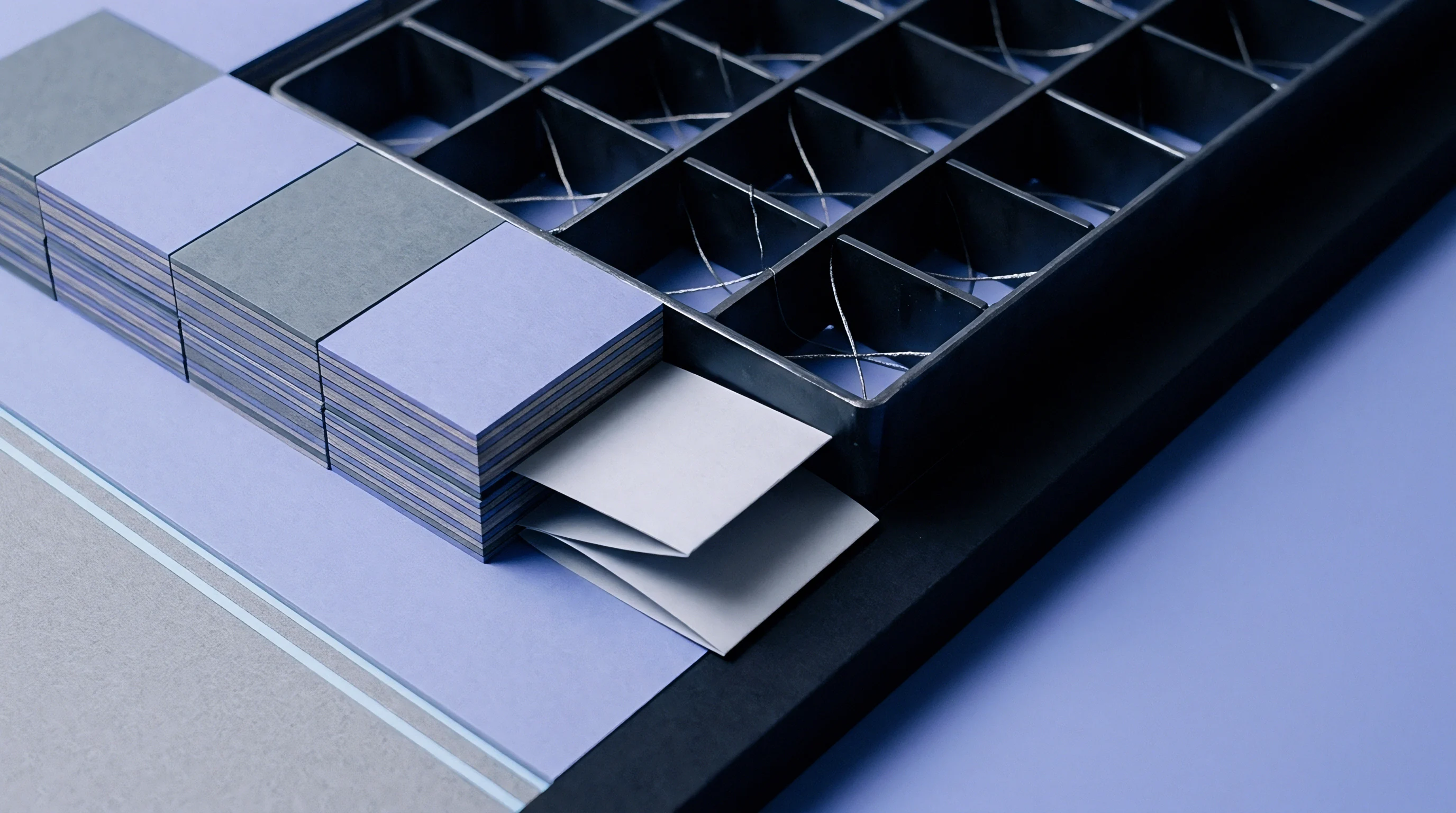
Mechanics
Creasing multilayer cartonboard forces a flat, multi-ply fiber structure into an engineered hinge without fracturing the outer print surface. When the steel creasing rule drives sheet stock down into an open counter matrix channel, the punch action exerts severe shear, transverse compression, and tensile loads across the board cross-section. Solid bleached sulfate boards, composed entirely of chemical pulp, deform with uniform internal elongation.
Multilayer folding boxboard behaves through an entirely different physical response: pigment-coated chemical pulp liners sandwich thick interior plies of mechanical thermo-mechanical or chemithermo-mechanical pulp. These middle plies possess high bulk and low interlaminar shear strength, designed specifically to yield under the tool strike.
Tensile stress spikes instantly.
As the creasing rule enters the substrate, the shear stresses between internal plies exceed the ply-bond resistance, causing deliberate, controlled delamination. This internal separation creates a distinct, hollow delamination bubble, termed the crease bead. The bead protrudes into the female channel beneath the platen.
If the channel opening provides insufficient space, the downward force shears directly through the top bleached liner, breaking the printed clay coating and degrading the finished barrier properties. An excessively wide channel disperses the forming force over too broad an area. The resulting crease exhibits inadequate ply separation, a wide and diffuse bend radius, and unpredictable crease recovery force during high-speed carton erection.
Crease bending resistance drops by up to thirty-five percent when channel clearance expands past twenty-five percent of nominal board thickness at fifty percent relative humidity.
The geometric relationship governing channel dimensions balances three physical values: the creasing rule thickness, the caliper of the cartonboard, and an empirical multiplier factor tied to fiber morphology. Traditional packaging tables prescribe a single flat equation: channel width equals the creasing rule width plus 1.5 times the board thickness. This conventional rule of thumb fails on modern multi-ply folding boxboard and coated recycled cartonboard grades running on automated, high-output packaging lines.
The crease bead splits.
Modern board formulations feature lower grammages achieved through high-yield mechanical pulping in central plies. These structures exhibit lower z-directional tensile strength and higher bulk than standard solid bleached grades. Specifying channel geometry with an uncorrected multiplier induces micro-cracking across the scoring ridge, visible under ten-times magnification as fractured pigment coating along folded carton edges.
Carton erecting lines running at four hundred packs per minute jam whenever the score profile drifts away from its targeted bending moment.
Surface liners fracture along scores.

Platen
Steel rule dies strike carton stock against a counter die positioned on the flatbed cylinder or cutting chase. Press operators historically applied pressboard or pertinence counters hand-cut with steel knives, introducing channel width variances of zero point zero five millimeters across a single layout. Modern manufacturing employs computerized milling of high-density paper-phenolic laminates, synthetic vulcanized fiberboards, and laser-hardened counter steel plates.
These computer-controlled milling cutters machine channel grooves with position tolerances within zero point zero one millimeters.
Rule profiles determine shear distribution.
The interaction between the cutting platen, the creasing knife edge, and the milled counter channel establishes the final score geometry. Standard creasing rules feature a fully rounded tip profile, although flat-ground and trapezoidal rule profiles see selection for thick cartonboard grades exceeding six hundred micrometers. The depth of the counter channel governs the height of the crease bead, while channel width governs lateral displacement and delamination clearance.
| Board Category | DIN 19303 Designation | Nominal Caliper Range (mm) | Scott Bond Range (J/m²) | Width Multiplier Factor k | Channel Depth Target |
|---|---|---|---|---|---|
| Solid Bleached Board | GZ / SBB | 0.30 to 0.65 | 190 to 280 | 1.35 to 1.45 | 1.00 × Caliper |
| Folding Boxboard Cream Back | GC2 / FBB | 0.35 to 0.80 | 110 to 160 | 1.60 to 1.75 | 1.05 × Caliper |
| Folding Boxboard White Back | GC1 / FBB | 0.30 to 0.75 | 130 to 180 | 1.50 to 1.65 | 1.05 × Caliper |
| White Lined Chipboard | GD2 / WLC | 0.40 to 0.90 | 80 to 130 | 1.70 to 1.85 | 1.10 × Caliper |
Tooling wear widens effective clearances.
Phenolic counter plates gradually compress under continuous impressions across an extended production run. Channel walls erode from abrasive contact with mineral pigment coatings, expanding the channel width by up to zero point zero four millimeters over seventy-five thousand impressions. Milled steel counters eliminate this progressive drift, holding exact geometry through multi-million carton programs, although they require precise platen leveling to prevent rule damage.
Die makers often attribute score fractures to normal board variation when dull milling heads burnish counter channel shoulders instead of cutting crisp right angles.


Delamination
Controlled internal layer separation determines whether a crease hinges cleanly or splits open. When the creasing rule drives down, compression directly underneath the rule tip compacts the fibers, transferring shear force sideways into the adjacent board planes. In structural mechanics, layered timber beams under transverse bending loads fail along resin boundary planes when horizontal shear surpasses adhesive bonding strength.
Similarly, multilayer cartonboard utilizes shear failure within central mechanical fiber layers as a functional mechanism, absorbing compressive deformation while exterior chemical fiber plies retain tensile integrity.
Milled channels demand sub-micron tolerances.
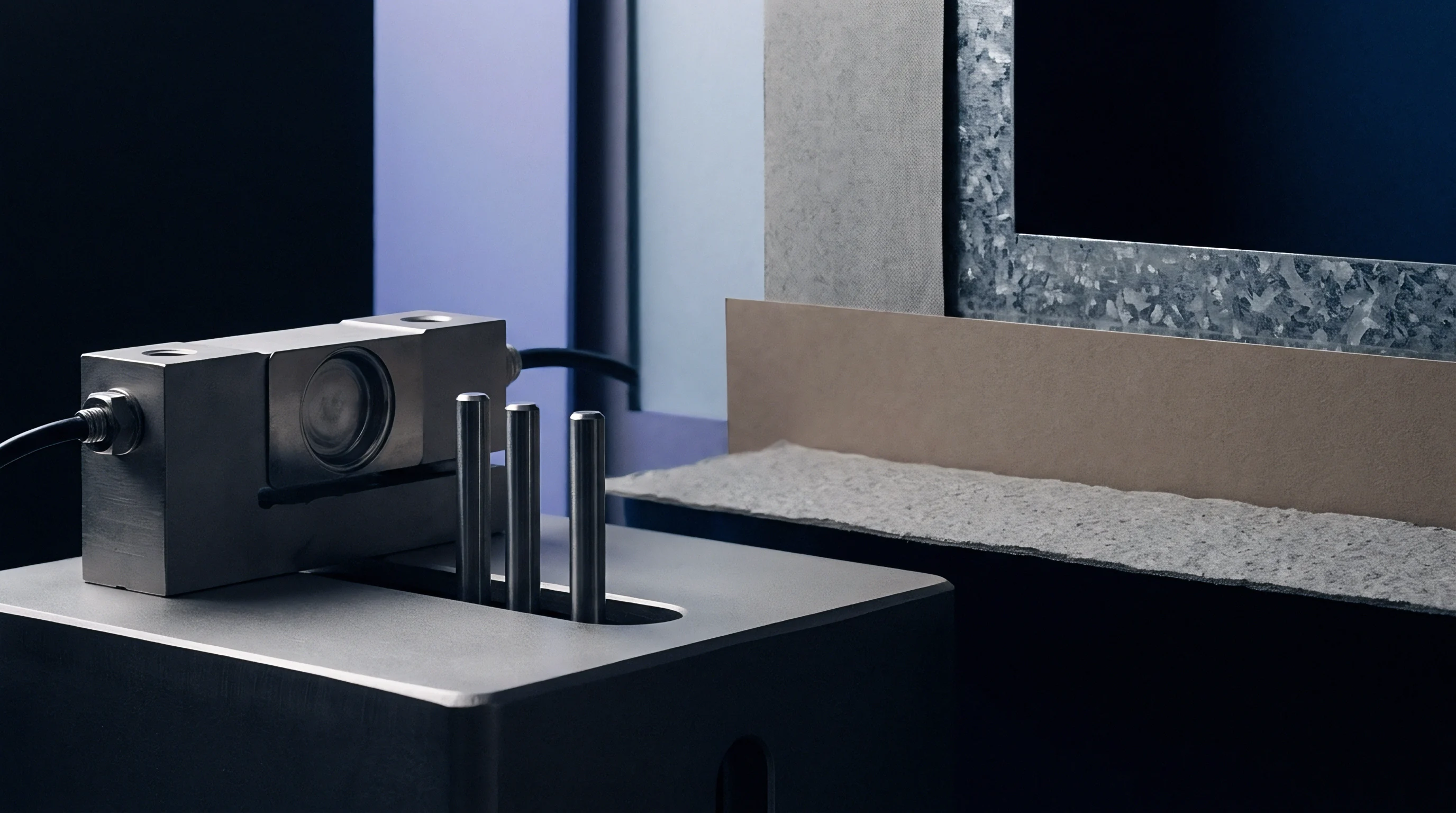
Does Central Ply Shear Determine Crease Bead Form?
Internal shear distribution dictates the internal volume of the crease bead. The Scott internal bond strength test, performed according to TAPPI T 569, measures the energy absorbed during rapid z-direction ply separation. Solid bleached boards exhibit Scott bond values between 190 and 280 Joules per square meter, requiring higher vertical rule penetration to trigger delamination.
Multilayer folding boxboard with chemithermo-mechanical middle plies yields at 110 to 160 Joules per square meter, permitting wider delamination spreading under moderate creasing pressure.
- Initial compression zone formation occurs when the rule tip contacts the upper liner, condensing surface fiber networks before downward displacement begins.
- Horizontal shear transmission initiates as lateral displacement forces adjacent fiber layers to slide across one another along inner ply interfaces.
- Inter-fiber bond failure propagates outward from the rule centerline toward the counter matrix channel edges, forming multiple discrete delamination tiers.
- Tensile strain stabilization prevents external liner cracking when internal shear relief redistributes elongation across outer coating layers.
Glue flaps misalign at speed.
If the channel width is cut too tight, the board cannot expand into the cavity, restricting horizontal delamination. The stress stays focused on the top coated liner, resulting in ruptured clay pigment and torn cellulose strands. If the counter channel is cut too broad, the delamination zone expands excessively, generating an asymmetrical, poorly defined crease bead.
Whether a specific chemithermo-mechanical pulp layer configuration can sustain localized delamination without collapsing under repeated reverse folds remains an unresolved engineering question for light-weighted board grades.

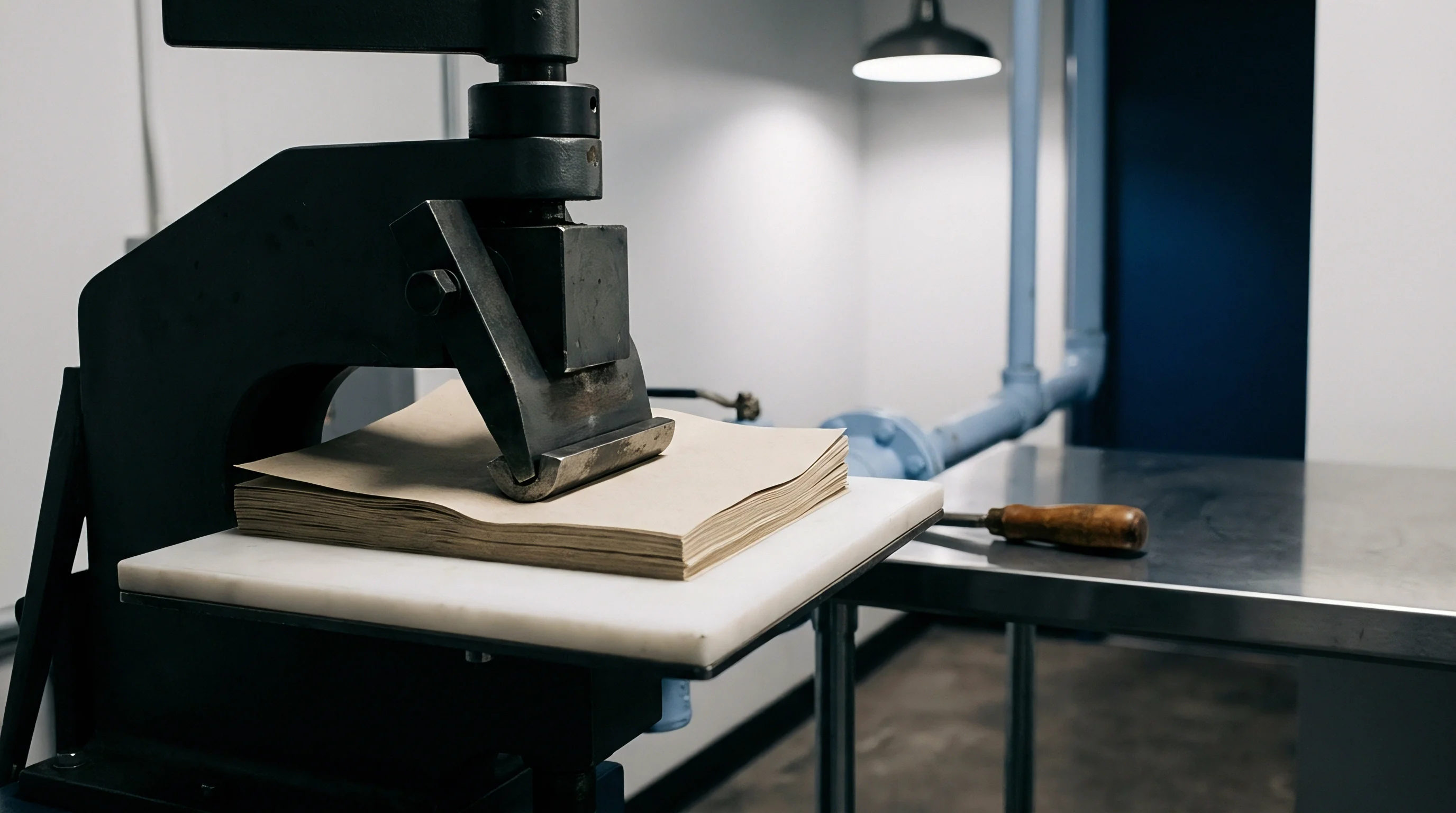
Variance
Raw material properties shift across production reels and environmental environments, demanding adaptive channel width calculations. Mill batch certificates report nominal calipers, yet production sheets exhibit thickness tolerances of plus or minus five percent across the cross-machine web. Moisture content introduces another operational variable: cellulose fibers absorb ambient humidity, swelling in diameter while losing inter-fiber cohesion.
Substrates conditioned at thirty-five percent relative humidity turn brittle, while those exposed to sixty-five percent relative humidity soften, increasing required channel clearance to accommodate swollen fibers.
Channel matrices cut for forty-five percent ambient relative humidity generate score edge peeling when converted in dry winter halls below twenty-five percent moisture equilibrium.
Calipers drift across shifts.

Will Coating Elasticity Alter Channel Clearance Demands?
Coating formulation and surface finishing directly modify the substrate’s response to creasing stresses. A standard double-coated mineral surface contains calcium carbonate, clay binders, and styrene-butadiene latex. While mineral pigments resist ink penetration, high pigment-to-binder ratios reduce flexibility, lowering the fracture threshold under outer-radius tensile bending.
When films or varnishes are applied to the sheet, the surface layer mechanics alter further.
- Biaxially oriented polypropylene film increases tensile elongation across carton scores, tolerating tighter channel geometry without surface rupture.
- Water-based barrier dispersions exhibit brittle film behavior under heavy rules, requiring wider channel matrix settings to prevent hairline fissures.
- Ultraviolet gloss varnishes crosslink into rigid polymeric networks, demanding an expansion of channel width by zero point zero five millimeters to eliminate surface crazing.
- Hot stamping foil layers introduce localized thermal stress during application, making the board underneath sensitive to excessive channel shear.
High humidity swells cellulose fibers.
Fiber grain alignment relative to the crease line plays an equal role in determining mechanical behavior. Machine direction creases run parallel to fiber orientation, forcing the creasing rule to displace fibers laterally with minimal cutting resistance. Cross-direction creases run perpendicular to fiber trunks, compelling the tool to bend fibers over channel shoulders.
Cross-direction creases demand channel clearances between five and ten percent wider than machine-direction creases to prevent fiber cleavage along the fold line. Matching channel width to fiber alignment preserves consistent score folding resistance without liner rupture.

Arithmetic
Accurate channel width formulas integrate board caliper, rule thickness, fiber orientation, and substrate-specific deformation coefficients. The baseline formula for counter die channel width separates the parameters into distinct linear factors:
W = R + (k_grain × k_mat × C)
In this relationship, W represents channel width in millimeters, R represents creasing rule thickness in millimeters, C represents conditioned board caliper in millimeters, k_mat represents the material deformation constant, and k_grain represents the fiber orientation coefficient. For machine direction creases, k_grain takes a value of 1.00. For cross-direction creases, k_grain increases to 1.08 to accommodate perpendicular fiber bending stiffness.
| Substrate Classification | Density Range (g/cm³) | MD Multiplier Constant | CD Multiplier Constant | Depth Multiplier (h) |
|---|---|---|---|---|
| Solid Bleached Sulfate (SBS) | 0.80 to 0.90 | 1.35 | 1.45 | 1.00 |
| Virgin Fiber FBB (GC1) | 0.65 to 0.75 | 1.50 | 1.62 | 1.05 |
| Bulky Mechanical FBB (GC2) | 0.55 to 0.65 | 1.60 | 1.75 | 1.05 |
| Recycled White Lined Chipboard (WLC) | 0.70 to 0.82 | 1.68 | 1.82 | 1.10 |
| Values determined under standard testing climate ISO 187 (23°C, 50% RH). Rule profile: 2-point (0.71 mm) rounded. | ||||
Carton lines reject skewed blanks.
Channel depth calculation follows an interrelated empirical formula:
D = h × C
In this equation, D represents counter channel depth in millimeters, C represents board caliper, and h represents the depth coefficient listed in the technical performance table. Standard practice uses matrix depth identical to nominal board caliper for solid bleached boards (h = 1.00). For bulky folding boxboard containing mechanical middle layers, setting h to 1.05 prevents bottom-out crushing of the bead crest against the channel floor.
Pertinax counters wear after fifty thousand sheets.
A worked engineering calculation demonstrates the impact of proper formula assignment. Assume an order of premium pharmaceutical cartons specifying 350-micrometer (0.350 mm) virgin fiber folding boxboard (GC1) converting with a standard two-point creasing rule (0.71 mm thickness):
For machine direction scores: W_MD = 0.71 mm + (1.00 × 1.50 × 0.350 mm) = 0.71 mm + 0.525 mm = 1.235 mm. The milling cutter specification rounds to 1.25 mm.
For cross-direction scores: W_CD = 0.71 mm + (1.08 × 1.50 × 0.350 mm) = 0.71 mm + 0.567 mm = 1.277 mm. The milling cutter specification rounds to 1.30 mm.
Channel depth target: D = 1.05 × 0.350 mm = 0.368 mm. Tooling specifies a 0.37 mm phenolic counter plate depth.
Standard packaging contracts stipulate compliance with DIN 55437-1 score assessment metrics, establishing that deviation exceeding ten percent of specified crease bending moment triggers batch rejection at incoming inspection.
Outlay
Tooling choices directly balance initial capital expense against make-ready waste and continuous press speeds. Die-cut tooling orders range from pre-formed polymer matrix strips applied by hand up to fully milled steel counter plates mounted on hardened steel backing sheets. Polymer matrices incur low tool room costs but increase platen make-ready duration and exhibit poor durability across long production runs.
Milled pertinax and steel plates demand higher upfront tooling investments, compensated by rapid make-ready registration and stable crease geometry across high-speed cartoning runs.
The folder gluer slows down.
| Counter Technology | Tool Cost Index | Make-Ready Time (Minutes) | Wear Limit (Impressions) | Defect Scrap Rate (%) |
|---|---|---|---|---|
| Polymer Matrix Strips | 1.0 | 45 to 60 | 25,000 | 2.8 to 4.2 |
| Milled Pertinax Plate | 3.5 | 15 to 25 | 80,000 | 0.8 to 1.4 |
| Milled Steel Counter Die | 9.0 | 10 to 15 | 500,000 | 0.3 to 0.6 |
A production run operating on twenty thousand sheets of coated recycled cartonboard reveals how scrap rates influence net costs. Incorrect channel width selections cause cartons to fold out of square on downstream folder-gluers running at forty-five thousand units per hour. A line rejection rate of three percent due to score cracking generates significant material spoilage, lost machine time, and reprint fees that outweigh the price difference of dedicated milled phenolic counter plates.
Converters running high-speed gluing equipment verify score performance through automated crease stiffness testing under ISO 2493-1 before releasing die-cut pallets to packaging lines. Milled counter channel tooling establishes consistent crease bending resistance across all blank positions, ensuring high packaging line output across multi-pallet delivery runs.