Polymer Film Micro Fracture Mechanisms under High Strain Shear in Folding Boxboard Creases
High strain shear during boxboard creasing causes polymer film micro fractures when local elongation exceeds film yield capacity along the outer bend radius.
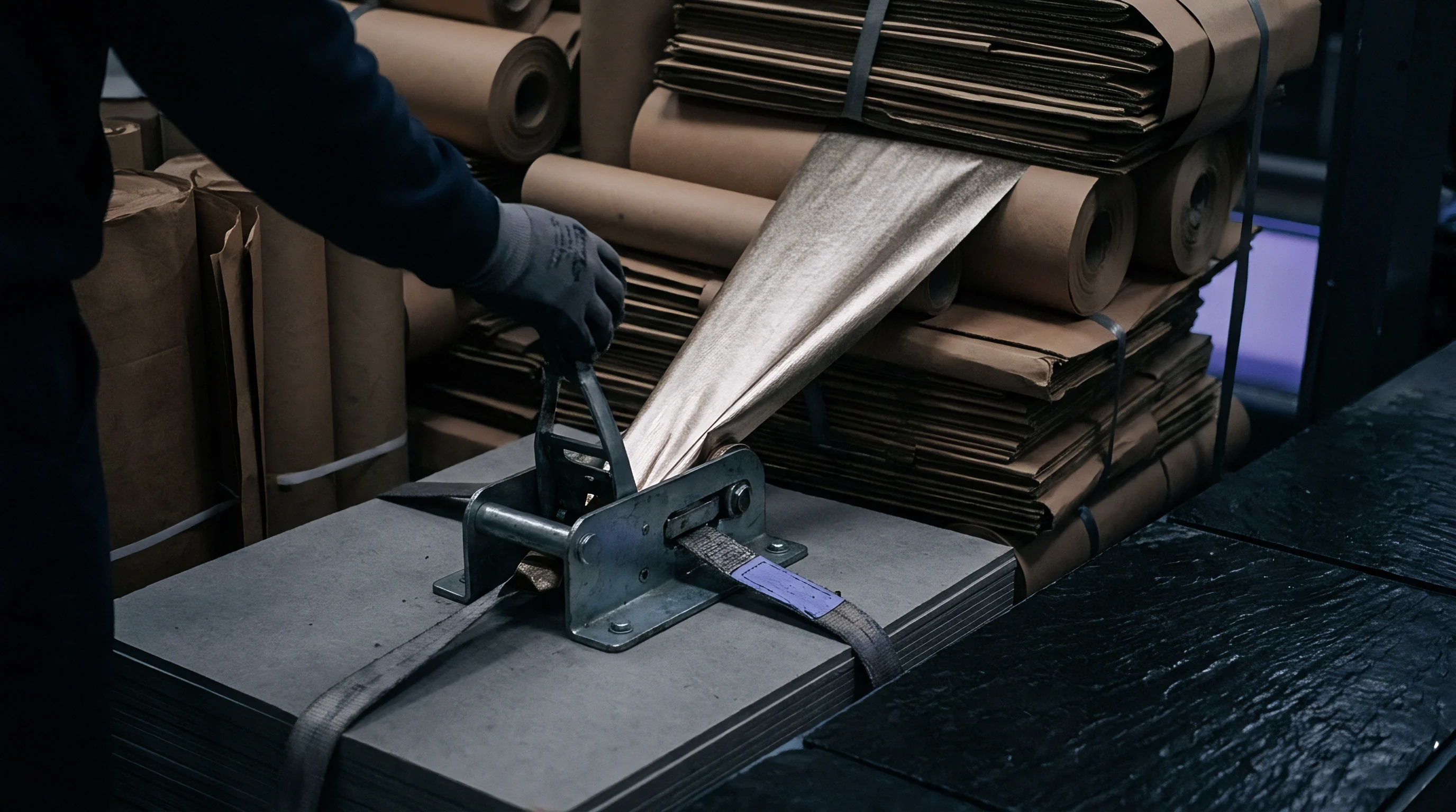

Crease
Mechanical deformation during carton blanking subjects barrier-coated substrates to localized displacement. On a die-cutter, male creasing rules force paperboard down into female channel matrices under vertical compression. This impression deliberately triggers an internal shear plane failure through the fibrous core while leaving outer surfaces intact.
Mechanical pulp in the center compresses, whereas outer layers of bleached chemical pulp endure flexural shear and tensile stretching. Adding an extruded or laminated polymer film alters this mechanical response. Because polymer films have a higher tensile modulus and greater strain rate sensitivity than cellulose fiber networks ~ and remain bonded to the top clay coating or bleached kraft fibers ~ they must absorb all tensile elongation along the outer bend radius during scoring and subsequent ninety-degree or one-hundred-and-eighty-degree folding.
Tensile stress builds along this outer radius. On a standard three-hundred-micrometer caliper folding boxboard sheet, outer radius elongation during a sharp ninety-degree fold reaches twelve to eighteen percent, depending on matrix channel width. At one hundred and eighty degrees, local strain at the outer polymer surface often tops twenty-five percent.
Cellulose fibers slip, shear, and split internally to absorb stress without rupturing the surface. Thin extruded polyolefin or polyester films lack internal delamination planes, concentrating all elongation within the polymer cross-section. When localized strain exceeds the polymer’s yield point or ultimate strain capacity at high converting speeds, micro fractures open along the score line.
These cracks compromise liquid tightness, moisture vapor barriers, and gas retention long before surface damage becomes visible.

Deformation Kinematics during Board Scoring
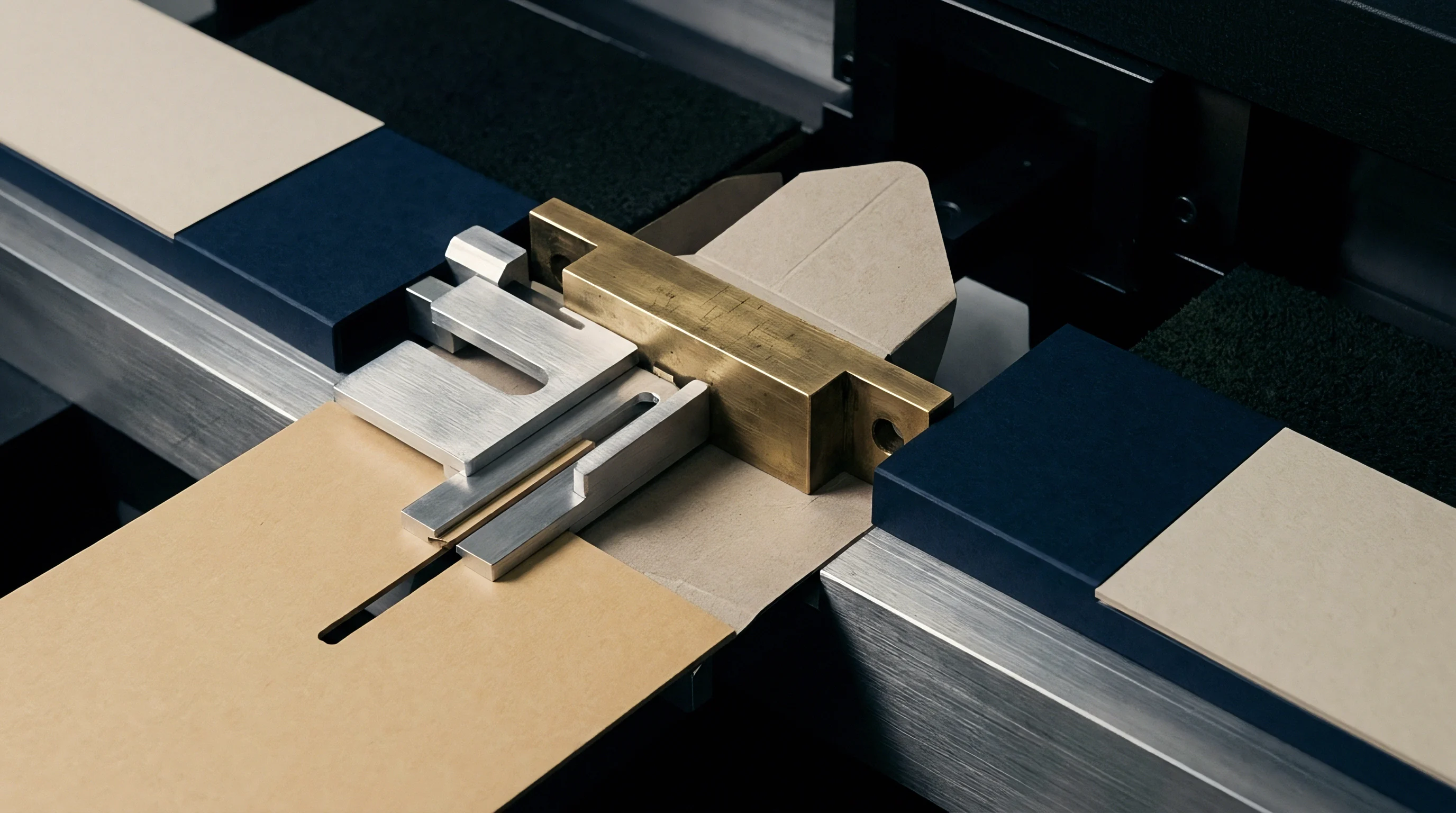
Scoring subjects multilayer paperboard to non-uniform strain along its z-axis. As the male rule drives into the top liner, it applies shear and transverse compression. Matrix channel edges support the sheet shoulders, creating twin shear zones.
Internal plies separate along weakened fiber bonds, forming a bead that projects toward the unprinted back side. This internal delamination absorbs bending shear. Measured as Delamination Shear Strength under TAPPI T 541 at twenty-three degrees Celsius and fifty percent relative humidity, it governs how cleanly the core splits into flexing layers.
If delamination strength is too high, the core resists internal ply separation, forcing the outer liner and polymer film around a tighter bending radius and driving up peak surface strain.
Lacking internal shear planes, the extrusion layer remains bound to the top liner, taking on the full tensile load from outer radius flexure. How that strain spreads across the score line depends on sheet orientation. Scoring across the web aligns machine-direction fibers parallel to the score rule, maximizing flexural resistance and creating steep strain gradients across the trough.
Scoring in the machine direction aligns fibers with the rule; resistance drops, though the board and film become more susceptible to longitudinal micro-splitting. Assessing stress along the score line involves measuring local thickness reduction at the score apex, where cross-sectional necking signals micro fracturing.
Strain Mechanics in Applied Barrier Coatings
How barrier polymers accommodate scoring strain depends on molecular weight distribution, crystallinity, and glass transition temperature. Low density polyethylene extrusion-coated at fifteen to twenty-five micrometers thickness shows a ductile yield stress between eight and twelve megapascals. Under slow deformation, it stretches elastically up to four percent strain before plastic necking begins and molecular chains realign.
But on autoplaten die-cutters running at eight thousand sheets per hour, deformation takes milliseconds. These high strain rates raise effective yield stress while restricting chain mobility, testing whether ductile polymers can deform without tearing.
Polyethylene terephthalate and poly-lactic acid barrier films have higher elastic moduli and lower elongation limits than polyolefins. Poly-lactic acid coatings have glass transition temperatures between fifty-five and sixty degrees Celsius, making them brittle under standard converting room conditions. Imposing twenty percent strain on a poly-lactic acid layer across a score line causes transverse micro-fissures with almost no plastic necking.
Mineral fillers, pigments, or contaminants in the substrate exacerbate these strain concentrations; hard particles act as stress risers beneath the polymer film, seeding micro-voids that drive outward under shear.
| Substrate Grade | Caliper (µm) | Coating Polymer | Film Caliper (µm) | Outer Strain (%) | Pinholes per Meter | Water Vapor Rate (g/m²·day) |
|---|---|---|---|---|---|---|
| Bleached Chemical FBB | 300 | LDPE Extrusion | 15 | 14.2 | 0.0 | 1.2 |
| Bleached Chemical FBB | 350 | LDPE Extrusion | 18 | 16.8 | 0.4 | 2.8 |
| Recycled WLC GT2 | 380 | LDPE Extrusion | 20 | 19.5 | 4.2 | 14.6 |
| Bleached Chemical FBB | 300 | PET Laminate | 12 | 13.8 | 8.1 | 22.1 |
| Bleached Chemical FBB | 300 | PLA Bio-Polymer | 20 | 14.1 | 18.5 | 68.4 |
Outer layer elongation during fold formation directly reflects sheet caliper and scoring tool geometry.
Substrate composition governs how strain distributes between paperboard and the polymer barrier. Recycled white-lined chipboards carry shorter fibers, higher ash content, and uneven internal bond strength compared to virgin folding boxboard. When scored, recycled board delaminates unpredictably, sending local strain spikes into the top liner.
Polymer coatings over these grades experience uneven stretching that accelerates micro-void formation along score edges. Virgin folding boxboard ~ built with a mechanical pulp core and double-bleached chemical pulp outer liners ~ delaminates in a clean, controlled manner. That consistent ply separation spreads tensile strain over a wider arc, preserving polymer integrity at identical sheet calipers.
Whether molecular relaxation over storage time can arrest late-stage crack growth remains unverified across commercial temperature ranges.

Rift
Microstructural failure in extrusion coatings develops through distinct stages under severe deformation. Prior to scoring, the polymer coating sits on the board as an isotropic or weakly oriented solid layer. When the male creasing rule strikes, localized shear forces align polymer chains along the strain axis.
Initial deformation is elastic and fully recovers if the load lifts. Once shear strain passes the yield threshold, molecular chains in amorphous zones uncoil and stretch. As displacement continues, crystalline lamellae tilt, slip, and fracture into smaller block structures, assembling fibrillar networks along main stress paths.
This fibrillar alignment allows substantial plastic deformation in ductile polymers like linear low density polyethylene. In stiffer or highly crystalline polymers, chain slipping cannot keep pace with high strain rates. Narrow shear bands form at forty-five-degree angles to the main tensile axis, creating localized zones of extreme softening and necking.
Ongoing shear forces cause crazing, with micro-voids nucleating around chain ends, density variations, or interface defects. As these voids link up, micro-fissures penetrate the entire thickness of the polymer film, ruining the barrier.
Micro Fracture Nucleation and Craze Development
Craze formation precedes structural fracture in semicrystalline barrier coatings. Crazes appear as microscopic planar voids spanned by oriented polymer fibrils between five and twenty nanometers thick. Under the tensile shear of creasing, these fibrils bear heavy tension until chains snap or disentangle.
When fibrils break, crazes grow into open micro-cracks. In extrusion-coated low density polyethylene, craze nucleation typically starts at ten to fourteen percent strain under ambient lab conditions.
How quickly stable crazes turn into open micro fractures depends heavily on film thickness uniformity. Web profile instability during extrusion coating produces periodic gauge variations across the web, leaving thin zones that concentrate stress during creasing. When a three-point rule strikes one of these thin areas, local shear strain spikes.
A fifteen percent drop in coating thickness increases local strain energy density by over thirty percent, driving rapid craze coalescence into continuous longitudinal fissures along the score apex.

Tie Layer Mechanics and Interface Debonding
Adhesion at the interface between polymer and paperboard dictates micro fracture geometry. Co-extruded structures rely on functionalized tie layers ~ such as maleic anhydride grafted polyethylene or ethylene acrylic acid copolymers ~ to bind non-polar polyolefins to polar cellulose or clay coatings. Strong interfacial adhesion forces the film to track top liner fiber elongation exactly.
If those top fibers rupture under high shear, the crack propagates directly into the adhering polymer film.
A moderate degree of interfacial debonding helps: it allows the film to unbind locally over a narrow band of twenty to fifty micrometers right at the score apex. This slight separation spreads total elongation over an unbonded section, keeping peak strain below the micro fracture threshold. Complete adhesion failure leads to broad peeling, flange lifting, and poor heat seals during carton assembly.
Achieving the right balance is essential ~ interfacial shear strength must resist widespread delamination while permitting micro-yielding at the score.
- Crazing Void Arrays are clusters of sub-micron planar voids bridged by oriented polymer chain fibrils under localized tension along score line edges.
- Shear Band Localization occurs when plastic strain concentrates within narrow forty-five-degree bands, causing cross-sectional necking prior to film tearing.
- Ductile Necking Rupture involves continuous thinning of the polymer layer until local tensile capacity falls below applied bending stress.
- Interfacial Delamination Cracks initiate at the film-substrate junction where shear stresses exceed tie-layer bond strength during sharp flexing.
- Pinhole Tear Junctions form where intersecting score lines create bi-axial shear stresses, opening micro-perforations at corner folds.
| Polymer Grade | Density (g/cm³) | Melt Index (g/10min) | Micro Fracture Strain (%) | Shear Strength (MPa) | Pinhole Index |
|---|---|---|---|---|---|
| Autoclave LDPE | 0.918 | 7.5 | 16.5 | 11.2 | Low |
| Tubular LDPE | 0.922 | 4.5 | 14.8 | 13.5 | Moderate |
| Metallocene LLDPE | 0.912 | 3.5 | 22.0 | 9.8 | Very Low |
| HDPE Blended Layer | 0.945 | 8.0 | 8.2 | 21.4 | High |
| Cast PET Film | 1.330 | N/A | 9.5 | 45.0 | Extreme |
| Amorphous PLA | 1.240 | 15.0 | 5.2 | 28.6 | Critical |
Polyethylene coatings exceeding eighteen micrometers exhibit a forty percent drop in pinhole resistance when conditioned below thirty percent relative humidity at twenty-three degrees Celsius.
Converting plant environments alter these polymer failure dynamics. Paperboard absorbs and loses moisture quickly, changing its stiffness and internal delamination behavior. In low relative humidity, core fibers stiffen and resist internal bead formation during creasing.
This forces the male rule to exert higher vertical pressure, raising shear stress across the top liner. At lower temperatures and low humidity, polymer coatings lose impact ductility, shifting from ductile necking to brittle fracture. Specifying cross-direction elongation limits for extrusion polymers helps prevent pinholes during winter converting when ambient plant humidity drops below thirty percent.
Matching male rule width to total board thickness prevents localized polymer stretching along fold lines.
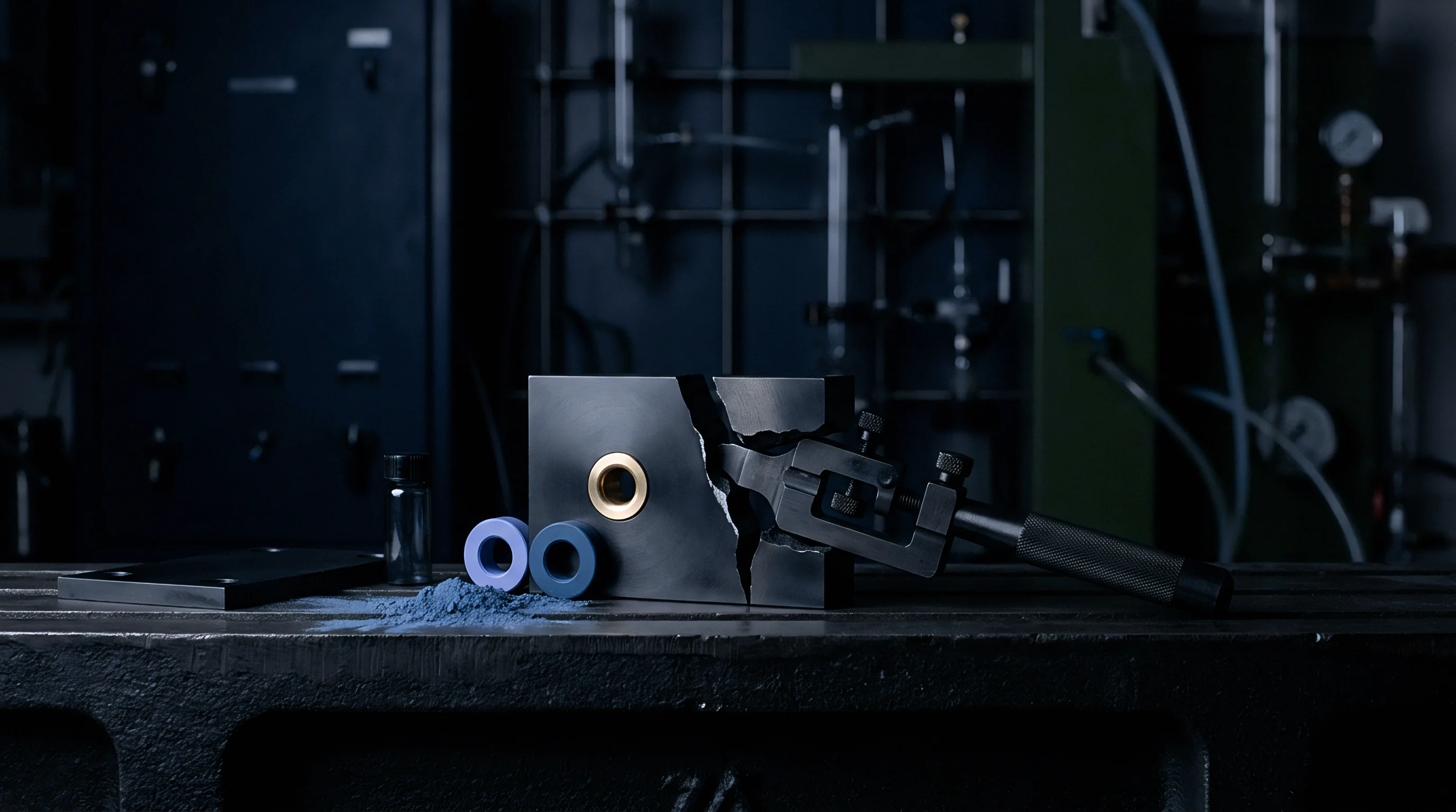
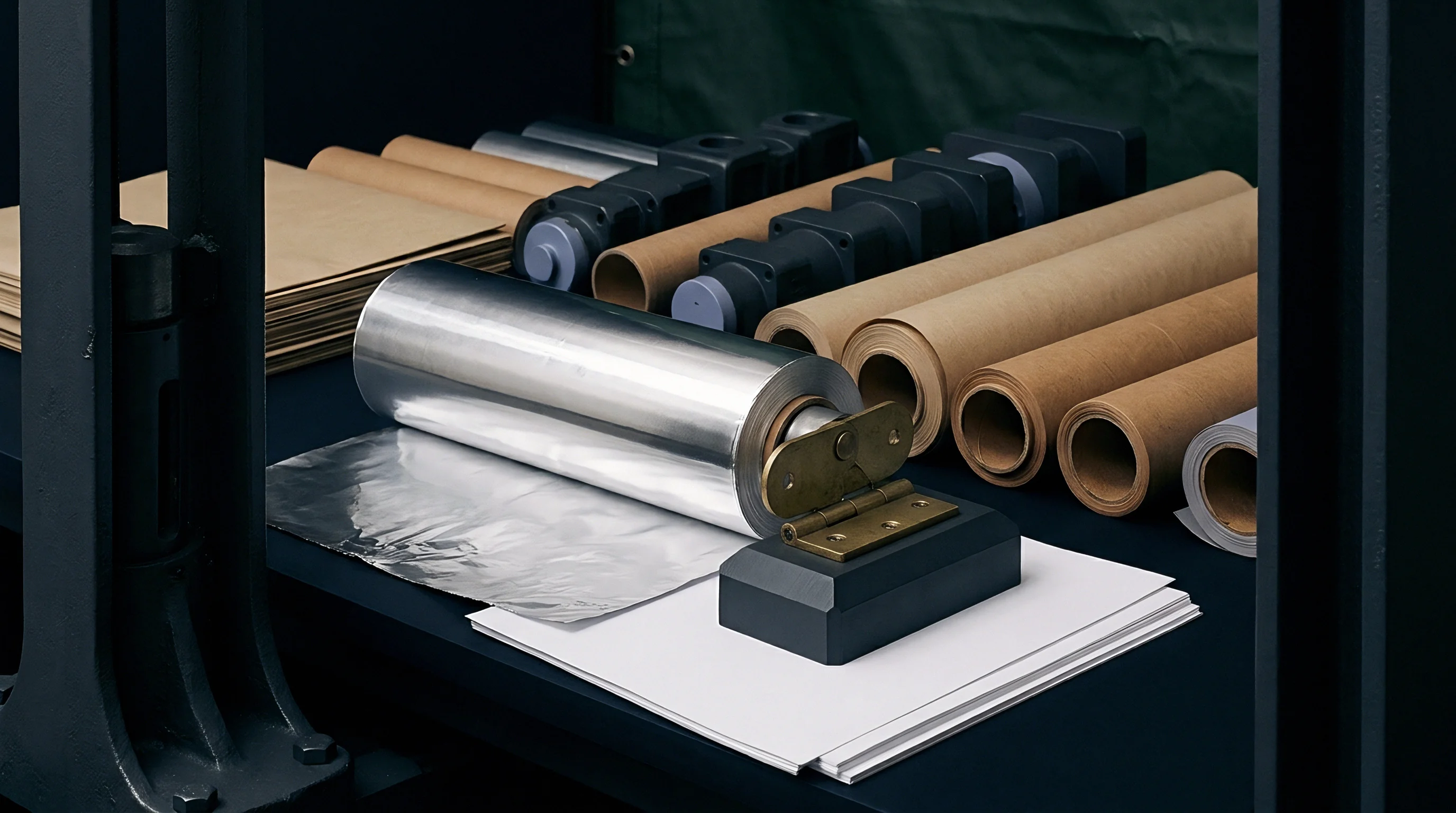
Tooling
Press adjustments during die-cutting dictate the mechanical forces applied to extrusion-coated board. Platen die-cutters use steel scoring rules driven into phenolic resin, vulcanized rubber, or pressboard channel matrices mounted on a steel plate. Together, rule geometry and channel dimensions establish clearance, compression ratio, and strain patterns across the score.
Incorrect tooling dimensions force unnecessary stretching in the polymer film, accelerating micro-fracture formation. Proper setup demands matching male rule width, tip radius, matrix channel width, and channel depth to substrate caliper and coating thickness.
Female matrix depth must accept the volume of displaced paperboard without crushing the core structure. If the matrix channel is too shallow, the displaced core bottoms out against the plate, generating high vertical compression that shears top liner fibers and tears the coating. Conversely, an overly deep channel lets the board sink without building enough internal delamination, yielding a loose score, poor folding accuracy, and high tensile strain on the outer radius.

When Does Matrix Width Cause Polymer Fracture?
Matrix channel width dictates the span over which paperboard flexes as the male rule penetrates. Standard creasing rules use a two-point thickness (zero point seven one millimeters) or a three-point thickness (one point zero five millimeters) with rounded tips. The standard rule-of-thumb formula sets female channel width at one point six times the measured board caliper plus the male rule thickness.
For an uncoated three-hundred-micrometer folding boxboard, a two-point rule pairs with a channel width of one point19 millimeters.
Coated boards need wider channels to safeguard the polymer layer. Adding a twenty-micrometer coating boosts board stiffness while lowering surface slip against matrix edges. On standard matrix widths, this causes sharp shear concentration against channel shoulders, which can tear the barrier layer.
Increasing the channel width multiplier from one point six to one point eight or two point zero creates a wider bend radius during scoring. That broader arc distributes tensile strain, keeping peak surface levels below the polymer’s micro fracture threshold.

Press Speed Dynamics and Anvil Clearance
Dynamic forces on autoplaten die-cutters running between six thousand and ten thousand sheets per hour significantly alter deformation rates. At high speeds, the male rule penetrates the matrix in under ten milliseconds. Polymers exhibit strong strain rate sensitivity: rapid deformation increases yield strength while cutting ultimate elongation.
Low density polyethylene that stretches three hundred percent in slow lab tests can fracture at twenty percent strain under high-speed press impact.
Anvil clearance and cutting plate pressure dictate penetration depth. Over-impressioning by as little as twenty micrometers past optimal bead depth causes a steep rise in shear stress on the top liner. Excessive pressure crushes the core completely, preventing ply separation and forcing the polymer film to absorb heavy compressive and shear forces.
Strain concentrates right where the rule presses the top ply against the matrix base, causing transverse micro-slits along the inner score shoulder.
- Verify ambient converting room conditions reach standard equilibrium before installing scoring matrix plates.
- Measure actual board caliper across the web profile using a calibrated micrometer under five kilopascals pressure.
- Select female channel width equal to scoring rule thickness plus one point six times measured board caliper.
- Set penetration depth of the scoring rule to achieve seventy percent core compaction without cutting outer fibers.
- Run test sheets at low press velocity to inspect male-female centerline alignment across all impressions.
- Increase autoplaten operational velocity to production speed while monitoring acoustic emission sensors for liner cracking.
| Board Caliper (µm) | Film Caliper (µm) | Rule Thickness (pt) | Rule Tip Radius (mm) | Matrix Width (mm) | Matrix Depth (mm) |
|---|---|---|---|---|---|
| 250–300 | 15 LDPE | 2 pt (0.71 mm) | 0.35 mm | 1.25–1.35 | 0.40 |
| 300–350 | 18 LDPE | 2 pt (0.71 mm) | 0.35 mm | 1.40–1.50 | 0.45 |
| 350–400 | 20 LDPE | 3 pt (1.05 mm) | 0.50 mm | 1.75–1.85 | 0.50 |
| 400–450 | 25 LDPE | 3 pt (1.05 mm) | 0.50 mm | 1.90–2.05 | 0.60 |
| 300–350 | 12 PET | 2 pt (0.71 mm) | 0.50 mm | 1.50–1.60 | 0.45 |
| 300–350 | 20 PLA | 2 pt (0.71 mm) | 0.50 mm | 1.55–1.65 | 0.45 |
Wider matrix channels reduce outer film stretch by allowing gradual fiber hinge formation.
Tooling wear adds uncontrolled variability to high-speed converting. Steel scoring rules flatten gradually after hundreds of thousands of impressions, widening the contact area and changing penetration dynamics. Matrix channel shoulders wear unevenly, creating tiny sharp edges that scrape the coating during insertion.
Routine maintenance requires checking rule tip profiles and replacing worn matrices before mechanical scraping triggers surface micro fractures.
Inadequate female clearance shears polymer barriers along folding edges, triggering product shelf life failure across distribution networks.

Audit
Effective quality protocols detect barrier damage long before fissures become visible. Standard visual inspection on scored folding boxboard cannot catch micro fractures hidden beneath clay coatings or inside transparent polymer films. Quality control requires destructive and non-destructive tests to pinpoint barrier loss along creases.
Measuring pinhole frequency, increases in gas transmission rates, and liquid penetration dynamics supplies the necessary verification for converting line compliance.
Solvent dye penetration testing offers immediate visual feedback on barrier continuity. Solutions containing glycol ether, isopropyl alcohol, and red or blue dyes penetrate micro-fissures within seconds of application to creased areas. Stained fiber patterns beneath the film mark the location and frequency of micro fractures.
Counting these dye spots per linear meter of score line provides a quantitative pinhole frequency rating for batch validation.
Dye Penetration and Permeability Diagnostics
Standard pinhole testing follows procedures in ISO 5636-3 and TAPPI T 559. A surfactant-modified dye solution is applied across folded score lines for five minutes under ambient room conditions. The solution wets the polymer surface, seeking out micro-voids, crazes, and shear tears.
When it finds a micro fracture, capillary action draws the dye through the film into the paperboard core. Once excess solvent is wiped away, technicians check the back side of the top liner for colored spots.
Gas transmission rate testing quantifies how scoring affects overall barrier performance. Water vapor transmission testing under ISO 15106-2 and oxygen transmission testing under ASTM F1927 compare uncreased board against samples with ninety-degree and one-hundred-and-eighty-degree folds. An undamaged fifteen-micrometer low density polyethylene coating exhibits a water vapor transmission rate of one point two grams per square meter per day at thirty-eight degrees Celsius and ninety percent relative humidity.
Micro fracturing across creases can increase this value five-fold to over six grams per square meter per day, rendering the material unfit for moisture-sensitive foods.

Microscopic and Fractographic Examination
Scanning Electron Microscopy delivers detailed fractographic analysis of micro fractures. Samples cut from score apexes are gold-sputtered before vacuum chamber inspection. SEM images highlight structural features characteristic of specific failure modes: ductile necking appears as smooth, drawn polymer edges around voids; brittle shear displays sharp, crystalline fracture surfaces with little thinning; and interfacial debonding shows clean separation between film and fibers, leaving fiber imprints in the adhesive.
Polarized light microscopy on cross-sectional microtome cuts allows visualization of internal stress distributions. Microtome blades slice five-micrometer sections across resin-embedded samples. Under polarized light, strain birefringence patterns in the polymer reveal residual stress zones along score shoulders.
Board stiffness dictates the female matrix clearance required to avoid high residual stresses that can trigger delayed micro fracture growth well after converting.
- Solvent Stain Inspection utilizes low-surface-tension dye solutions applied to folded creases to expose micro-fissures through capillary staining of core fibers.
- Cross Sectional Microtomy embeds creased samples in resin to slice thin segments for polarized light microscopic analysis of polymer necking and ply shear.
- Gas Permeability Screening measures oxygen and moisture vapor transmission rates across folded blanks to quantify barrier degradation relative to flat stock.
- High Strain Dynamic Bending subjects creased board to repeated flex cycles while measuring acoustic emission signals to detect progressive polymer cracking.
Standard specification EN 13676 mandates zero pinhole penetration across creased barrier edges when tested with isopropyl alcohol dye solutions for five minutes.
Automated inline inspection systems on modern die-cutters incorporate high-resolution camera arrays and spectral imaging. Positioned post-stripping, machine vision cameras capture reflected ultraviolet light passed through fluorescence-doped polymer coatings. Micro fractures shift UV refraction, pinpointing cracks in real time at full line speed.
These immediate inline diagnostics let operators adjust platen depth or replace worn matrices as soon as early barrier defects appear, heading off production runs of defective cartons.
Score line barrier failure often stems from excessive press speed or unconditioned converting environments rather than coating ductility limits.

Waste
Financial losses in high-barrier carton production stem mainly from hidden microstructural damage during creasing. When barrier coatings crack during converting, defective cartons pass through gluing, packing, and shipping unnoticed. The failure surfaces only after filling, warehousing, or retail delivery, resulting in spoiled product, claims, and brand damage.
Keeping landed costs down requires balancing polymer specifications, substrate properties, and converting settings.
Downgauging extrusion coatings saves directly on resin, but narrows the converting process window. Reducing low density polyethylene coating thickness from twenty to twelve micrometers cuts polymer usage by seven point4 grams per square meter. On a board machine producing ten thousand tonnes of barrier board per year, that reduction saves over seven hundred thousand dollars in raw materials.
However, pinholes destroy shelf life. Thin coatings are far more sensitive to scoring shear, lifting creasing micro-fracture rates from zero point one percent to over four percent under standard converting tolerances. Spoilage costs and rejection penalties quickly wipe out resin savings.
Yield Loss and Downgauge Risk Metrics
Evaluating barrier board economics means balancing film weight against expected scrap rates. Total landed cost per thousand cartons accounts for substrate, polymer coating, converting time, and risk allowances for field failures. A three-hundred-gram folding boxboard with a fifteen-micrometer LDPE coating costs roughly one thousand eight hundred dollars per tonne delivered.
At a blank weight of thirty grams per carton, raw substrate costs equal fifty-four dollars per thousand cartons. Converting spoilage from score line pinholes adds direct scrap expenses alongside lost machine capacity.
Yield drops quickly when scoring fails, and higher line speeds only intensify the shear. If micro fracturing forces a press de-rating from eight thousand down to five thousand sheets per hour to protect the film, hourly operating costs rise by thirty-seven percent. Blending linear low density polyethylene into standard LDPE raises resin cost by five percent, but restores high-speed converting headroom.
That yield stability ultimately lowers the total cost per thousand defect-free cartons.
Commercial Specification and Penalty Structures
Procurement specifications for substrate board should include explicit mechanical performance standards for barrier coatings beyond basic weight and bulk requirements. Contracts that specify only coat weight leave buyers vulnerable to brittle polymer grades or weak interfacial bonding. Specifications ought to mandate minimum cross-direction polymer elongation at break under ISO 527-3, minimum Z-direction delamination strength under TAPPI T 541, and maximum allowable post-creasing pinhole frequency under EN 13676.
Clear penalty structures in supply contracts establish financial responsibility for converting failures. When delivered reels fail crease qualification tests because of coating brittleness or thickness variations, agreed clauses cover credit terms, reel replacement, and press downtime compensation. Standardized verification encourages suppliers to maintain tight control over melt index, density, and extrusion temperature profiles, ensuring reliable performance on the converting floor.
Including ISO 527-3 cross-direction elongation thresholds of three hundred percent within substrate purchase contracts transfers financial liability for crease pinholing back to the board coater.