Measuring Paperboard Crease Profiles Using Non-Contact Triangulation Sensors
Blue laser triangulation resolves paperboard crease bead topography within two micrometers, eliminating red-light fiber scattering and manual micrometer error.

Optics
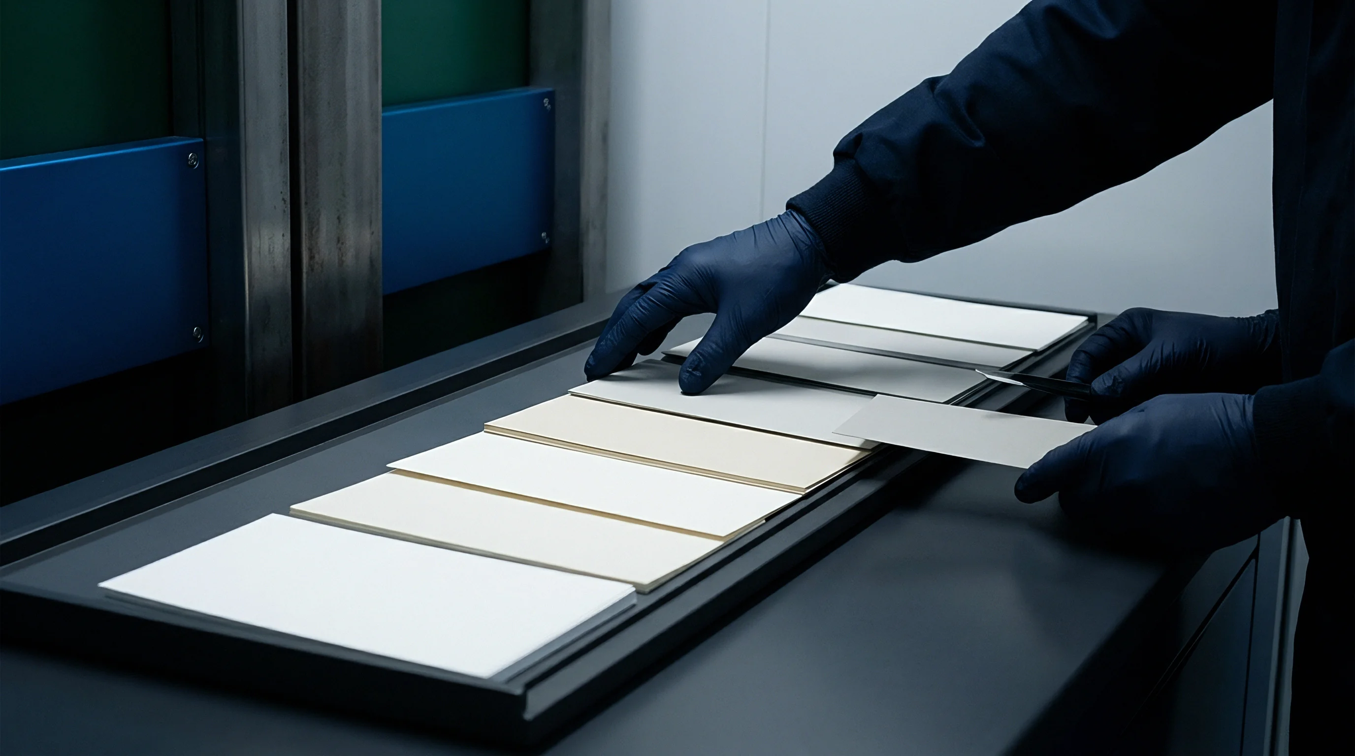
Non-contact triangulation instruments project a focused semiconductor laser line across the creased sheet while an area-scan CMOS matrix collects the diffuse reflection at a fixed scheimpflug angle. Surface elevation coordinates calculate directly from pixel displacement along the imaging sensor array. Wavelength determines optical penetration depth.
When measuring unprinted cartonboard grades, standard 650-nanometer red laser diodes enter the uncalendered fiber network, traveling forty to one hundred micrometers beneath the top liner before backscattering to the camera. This volume scattering shifts the calculated centroid of the laser line toward the board bulk. A calibrated gauge running red illumination understates crease depth on solid bleached sulphate board by up to eighteen micrometers.
Blue diodes operating at 405 nanometers solve this subsurface diffusion. The shorter wavelength interacts with the top mineral coating layer, reflecting from the calcium carbonate and kaolin platelets without entering the cellulose base. Blue diodes eliminate surface translucency errors.
Cellulose fibers scatter red laser light. Laboratory verifications confirm that switching from 650 nanometers to 405 nanometers restricts beam penetration to less than four micrometers on double-coated folding boxboard. Optics replace mechanical dial indicators.
The resulting elevation map matches physical contact stylus measurements within two micrometers of vertical displacement across the entire profile width.
Surface illumination angle dictates sensor return stability over unvarnished bleached pulp.
The geometric relationship between the projection axis, the target surface, and the imaging receiver establishes measurement repeatability. Standard sensor heads deploy a thirty-degree or forty-five-degree triangulation angle. Steeper angles reduce optical shadowing within steep crease channels, though they narrow the effective vertical measuring range.
Shallow angles expand vertical resolution across the crease shoulders, yet they induce occlusion errors along the steep sidewalls of deep scores. High-speed inline heads maintain a working distance between sixty and one hundred millimeters to prevent physical board flutter from contacting the sensor glass.
Signal processing algorithms extract the profile coordinates through sub-pixel peak detection methods. Gaussian curve fitting and center-of-gravity calculations convert the imaged stripe intensity distribution into discrete elevation points. Raw intensity data passes through digital thresholding to isolate valid surface reflections from ambient illumination and electrical noise.
- Speckle Interference introduces high-frequency spatial noise across the raw laser profile when coherent light reflects from rough uncalendered fibers.
- Secondary Reflections bounce between the steep opposing sidewalls of narrow female matrix grooves, projecting false secondary peaks onto the sensor array.
- Subsurface Attenuation degrades return signal intensity on unbleached kraft liners, altering the signal-to-noise ratio across unprinted score segments.
- Triangulation Occlusion hides the deepest base coordinate of the crease groove when asymmetric bead formations block the line of sight to the receiver.
Static bench instruments eliminate sheet vibration by clamping the specimen against an anodized vacuum anvil under controlled tension. Inline converting installations mount the sensor assembly above an open web run supported by a precision ground steel idler drum. Web tension over the idler suppresses vertical displacement, holding board position within a fifteen-micrometer focus tolerance window.
The digitizer samples profiles at line speeds reaching eight hundred meters per minute, generating dense longitudinal point clouds along the running web.

Bead
Mechanical creasing forces a rounded steel rule into paperboard supported by a counter-matrix channel, creating an intentional internal delamination network. The creasing rule drives downward. Under compressive load, the board structure yields in shear along its inner plies, forming an inverted rib termed the crease bead.
This permanent shear failure allows carton panels to fold ninety or one hundred and eighty degrees without cracking the exterior clay coating or printed ink film. Triangulation sensors capture the entire cross-sectional topography of this structure, quantifying parameters that manual micrometers flatten and destroy.
Profile evaluation centers on four discrete geometric values: groove depth, groove width, bead height, and internal crease symmetry. Groove depth records the vertical distance from the uncreased board surface to the deepest point of the rule indentation. Groove width measures the horizontal span between the outer shoulder inflection points where the board begins curving inward.
Bead height measures the downward extension of the internal board plies past the bottom plane of the sheet into the female matrix cavity. Die pressure dictates score definition. A correctly formed crease displays a symmetric bead whose internal fiber layers separate into clean, distinct laminations without rupturing the tensile face.
A ten-micrometer drop in residual crease caliper beneath the rule increases folding resistance by twelve percent on 350-gram folding boxboard.
Tensile rupture destroys outer plies. When creasing conditions apply excessive vertical stroke, shear forces tear the top liner, releasing structural tension and weakening the finished carton corner. Conversely, insufficient rule penetration fails to initiate internal delamination, leaving the board stiff and prone to uncontrolled diagonal folding during gluing operations.
- Top Liner Tension concentrates tensile strain along the exterior coated surface directly beneath the rounded tip of the male rule during initial matrix entry.
- Interlayer Shear Separation cleaves the chemical and mechanical bonds between virgin pulp plies, generating localized delamination zones adjacent to the crease shoulders.
- Matrix Channel Confinement forces loosened core fibers into the female groove volume, defining the ultimate width and profile radius of the protruding bead.
- Elastic Springback lifts the central region of the bead toward the neutral board plane immediately following dynamic tool withdrawal from the counter-matrix.
Triangulation software calculates the symmetry ratio by dividing the distance from the bead apex to the left shoulder by the distance from the apex to the right shoulder. Symmetrical creases yield a ratio between 0.95 and 1.05. Misaligned diecutting tools push this ratio beyond 1.20, shifting the folding hinge off-center.
When folded on automated folder-gluers, asymmetric creases generate uneven panel gap margins, skewed cartons, and fish-tailing glue seams that fail downstream automated filling lines.
| Board Grade | Grammage (g/m²) | Caliper (µm) | Rule Thickness (pt) | Matrix Width (mm) | Channel Depth (mm) | Target Bead Height (µm) |
|---|---|---|---|---|---|---|
| Solid Bleached Sulphate | 280 | 380 | 2.0 | 1.20 | 0.40 | 295 |
| Solid Bleached Sulphate | 350 | 490 | 2.0 | 1.50 | 0.50 | 385 |
| Folding Boxboard | 300 | 460 | 2.0 | 1.40 | 0.50 | 360 |
| Folding Boxboard | 380 | 600 | 3.0 | 1.80 | 0.60 | 475 |
| Coated Recycled Board | 350 | 450 | 2.0 | 1.50 | 0.50 | 340 |
| Coated Recycled Board | 450 | 610 | 3.0 | 1.90 | 0.70 | 465 |
| Data compiled from standard converting guidelines under 23 degrees Celsius and 50 percent relative humidity; bead height measured by 405-nanometer triangulation sensor within five minutes of platen impression. | ||||||
Deep delamination within the carton core preserves the printed surface during high-speed folding.
Drift
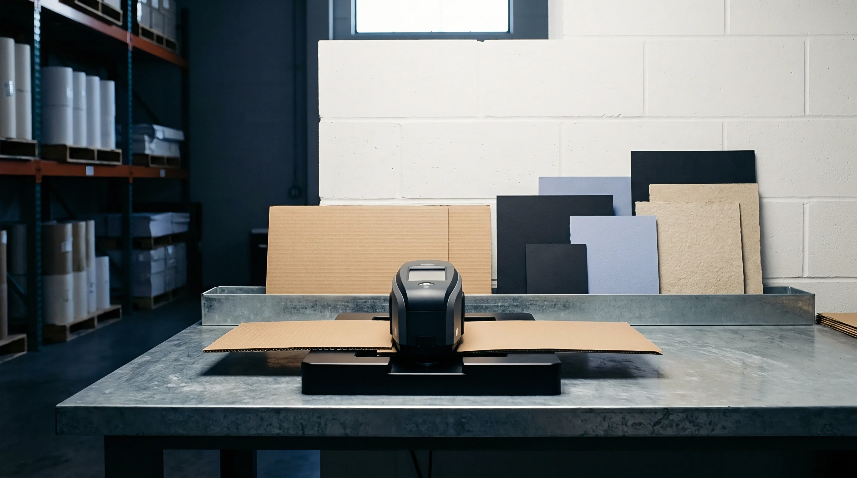
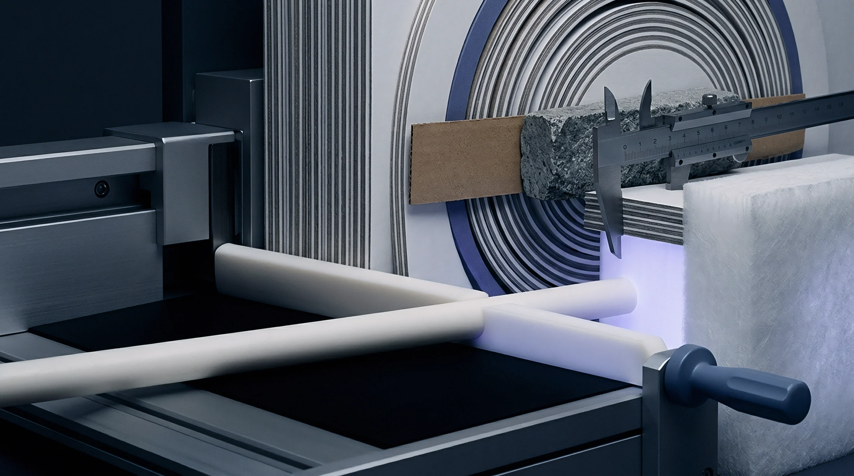
Flatbed platen diecutters run production cycles at seven thousand sheets per hour, subjecting steel cutting rules and counter-dies to sustained mechanical fatigue. Tool steel outlasts phenolic counters. Channel walls composed of milled Pertinax or laminated vulcanized fiber absorb repetitive lateral impacts from the male rule.
As running volume mounts, this constant pounding deforms the channel boundaries. Matrix channels widen gradually across long runs, altering the volume available for fiber delamination.

Does Matrix Wear Alter Bead Symmetry across Shifts?
Counter-matrix channel walls degrade along the lead edges facing sheet feed direction. The continuous passage of abrasive paperboard edges, combined with micro-movements of the creasing rule under platen tonnage, rounds off the defined corners of phenolic counter-channels. Pertinax channels wear along the shoulders.
Triangulation sensors track this degradation by logging profile geometry across thousands of successive blanks. When shoulder definition deteriorates, the female groove broadens. The paperboard core spreads laterally instead of compacting vertically, flattening the bead apex and extending the measured crease width by twenty to fifty micrometers over fifty thousand impressions.
Channel shoulder displacement reveals matrix adhesive failure long before carton blanks jam the folder-gluer feed hopper.
Mechanical wear manifests unevenly across large-format platen chases. Triangulation audits across multi-up die layouts frequently reveal progressive geometric variance between individual carton blanks extracted from the center of the platen versus those cut along chase perimeters. Center positions experience higher structural deflection under peak tonnage, which compresses the rule stroke and produces shallower groove depths.
- Platen Deflection reduces the vertical penetration depth of rules positioned across the center of large-format die beds.
- Tape Compaction under make-ready patches degrades channel support, lowering bead height over extended running shifts.
- Channel Flaking tears phenolic channel sidewalls, creating asymmetric resistance that skews the crease bead centerline.
- Thermal Expansion of the carbon steel die chase shifts rule alignment relative to the base counter-matrix plate during long runs.
Die tooling suppliers frequently assert that running board dust accounts for sensor measurement drift when matrix channels widen under sustained tonnage.


Scatter
Surface treatments applied during finishing modify the reflective behavior of paperboard blanks, challenging optical triangulation systems. High-gloss UV varnishes, cold foils, and hot-stamped metallic areas replace the lambertian scattering of raw paperboard with pure specular reflection. Specular reflections blind image sensors.
When a focused laser stripe encounters a mirror-like finish, incident photons reflect directly into the imaging lens at angles matching the illumination angle, saturating the CMOS sensor wells and causing signal blooming across adjacent pixels.
Is Blue Laser Triangulation Reliable over Stamped Foil?
Direct specular return across metallic foil creases obliterates the true peak coordinate, replacing it with an overexposed, clipped whiteout zone spanning multiple sub-pixel columns. Conversely, tilted crease sidewalls deflect the specular beam away from the sensor lens entirely, leaving zero signal return and producing artificial data dropouts in the reconstructed profile. Polypropylene films stretch during creasing.
Polymer-laminated folding boxboard combines specular surface reflection with internal film elasticity. When the creasing rule strikes a film-laminated board, the plastic layer elongates over the score without tearing, forming a smooth, mirror-finish valley over a fractured, porous fiber core.
| Surface Finish Pass | Optical Characteristic | 405 nm Laser Repeatability (µm) | 650 nm Laser Repeatability (µm) | Signal Dropout Frequency (%) |
|---|---|---|---|---|
| Uncoated Virgin Pulp | Diffuse, High Subsurface Penetration | 1.8 | 6.4 | 0.0 |
| Double Clay Coated Matte | Diffuse, Low Penetration | 1.2 | 2.9 | 0.0 |
| Gloss Water-Based Coating | Mixed Specular and Diffuse | 2.1 | 4.1 | 0.2 |
| High-Gloss UV Screen Varnish | High Specular Glare | 4.5 | 8.7 | 1.8 |
| Thermal Matte OPP Film | Diffuse Surface, Elastic Substrate | 2.4 | 3.8 | 0.1 |
| Hot Stamped Aluminum Foil | Total Specular Mirror | 6.8 | 14.2 | 4.5 |
Modern non-contact triangulation systems mitigate finish-induced errors by employing high dynamic range CMOS arrays paired with real-time exposure modulation. The sensor microprocessor alternates exposure duration frame by frame, capturing dark exposures to resolve over-saturated foil highlights alongside long exposures to detect low-intensity returns from shadowed matrix grooves. Crossed polarization optics filter out direct specular glare, passing only depolarized diffuse reflections from the coating interface to the detector array.
Diffraction grating techniques expand single-line triangulation into dense multi-line projections. By sweeping ten parallel laser stripes simultaneously across the crease zone, the sensor captures redundant profile slices within a five-millimeter web advance. Software filters compare adjacent line profiles, rejecting erratic data points caused by localized foil pinholes or isolated dust particles.
The processed elevation matrix stitches these slices into an uninterrupted three-dimensional topography of the embossed or varnished score.
Whether optical sensor manufacturers can construct an automatic exposure engine capable of resolving holographic foil embossing alongside matte dispersion coatings within a single five-millisecond scan cycle remains undetermined.

Settlement
Crease profile geometry governs the mechanical performance of carton blanks on high-speed folder-gluers. High-speed folder-gluers reject asymmetrical blanks. Packaging lines processing pharmaceutical cartons and food packaging operate at speeds up to one hundred thousand units per hour.
These machines feed flat blanks via suction cups, presetting the primary scores by folding panels one hundred and eighty degrees before opening them, applying adhesive, and pressing them flat. Gluer belts demand uniform crease stiffness.
When crease depth falls below eighty percent of board caliper, folding resistance surges. Stiff, incompletely delaminated creases refuse to fold smoothly along the score axis, causing cartons to bow outwardly. Excessive folding force overloads folder-gluer belts, skewing panels out of register and producing crooked, unsquare carton sleeves.
Conversely, overly aggressive creasing that crushes the residual board caliper below fifty percent compromises corner rigidity, leading to panel collapse inside automatic cartoning lines.
DIN 55437 acceptance limits enforce commercial rejection when symmetrical bead deviation exceeds five percent of nominal groove width.
Carton jams idle downstream packers. Converting plants link offline or inline triangulation gauges directly to their enterprise production ledgers to establish automated reject protocols. Tracking profile drift in real time enables operators to identify die wear before defective blanks reach the finishing department.
Verifying crease geometry on the first production sheet off the platen eliminates costly make-ready waste, preventing uncreased or misaligned pallets from entering post-press processing.
| Profile Deviation Band | Folder-Gluer Speed (blanks/hr) | Carton Jam Frequency (%) | Waste Rate per Shift (%) | Direct Downstream Downtime Cost per Shift ($) |
|---|---|---|---|---|
| Nominal (Bead Height ±10 µm) | 95,000 | 0.02 | 0.4 | 120 |
| Moderate (Bead Height -25 µm) | 75,000 | 0.28 | 1.8 | 850 |
| Severe (Bead Height -50 µm) | 45,000 | 1.45 | 6.2 | 3,400 |
| Asymmetric (Axis Offset >40 µm) | 50,000 | 2.10 | 8.5 | 4,800 |
Implementing non-contact triangulation sensors as an incoming quality acceptance standard allows packaging buyers to benchmark converting quality objectively. Procurement agreements referencing empirical sensor data replace subjective manual folding tests with auditable numerical tolerances.
- Baseline Gauge Calibration aligns sensor coordinate systems against certified optical step height masters traceable to national metrology standards.
- Substrate Atmospheric Conditioning stabilizes board moisture content under ISO 187 parameters prior to profile acquisition.
- Multi-Point Crease Verification measures scores along both machine direction and cross direction to account for fiber grain anisotropy.
- Statistical Process Limits flag platen tool wear whenever running bead height variance exceeds three standard deviations from approved make-ready draws.
Incorporating DIN 55437 Section 4 tolerance limits directly into carton procurement contracts transfers the financial burden of folder-gluer downtime from the packaging line operator to the cartonboard converter whenever mean bead height falls below ninety percent of specified matrix depth.