Creasing Die Geometry Adjustments for Barrier Film Integrity Preservation
Modifying creasing matrix channel width and male rule tip radius prevents polymer film elongation cracking and maintains gas barrier integrity across folded scores.
Groove
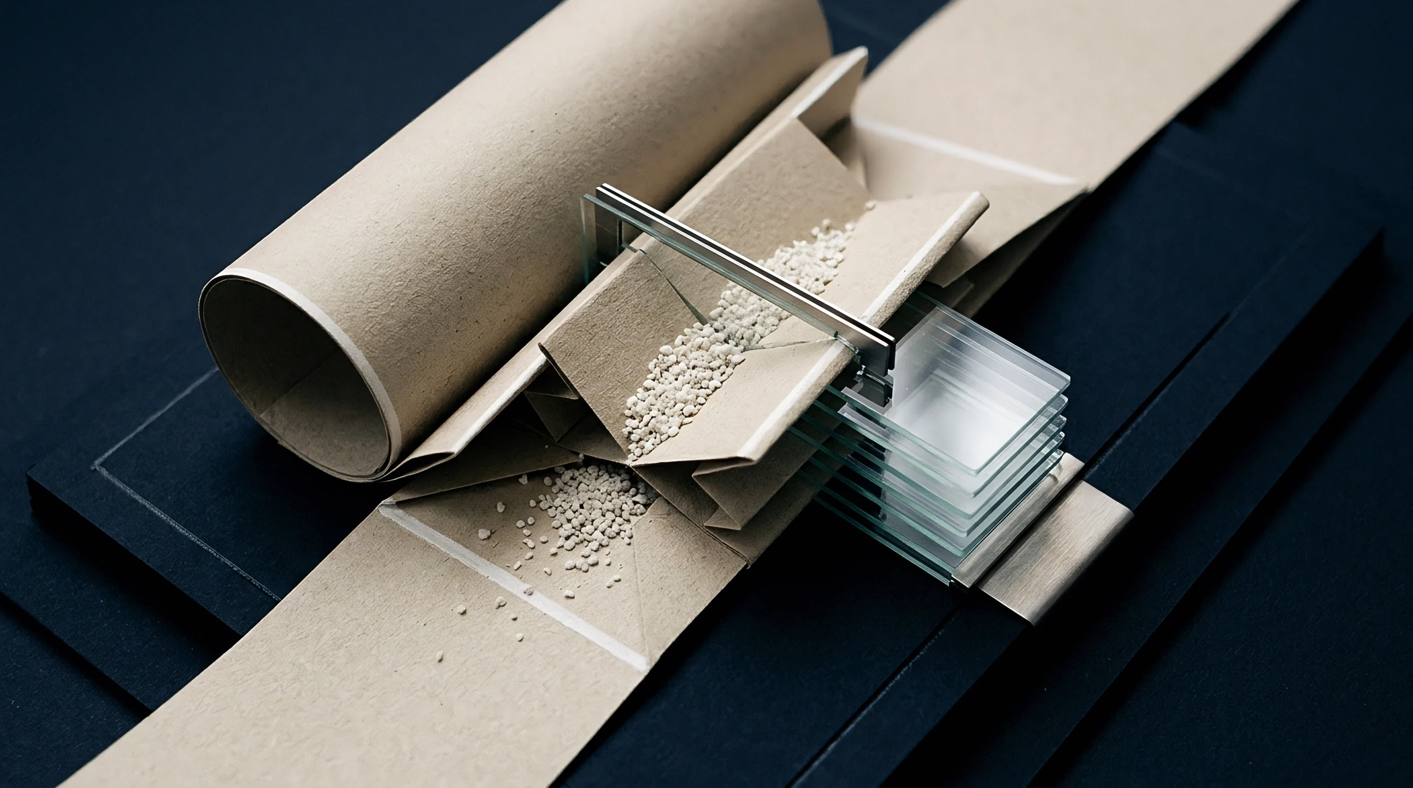
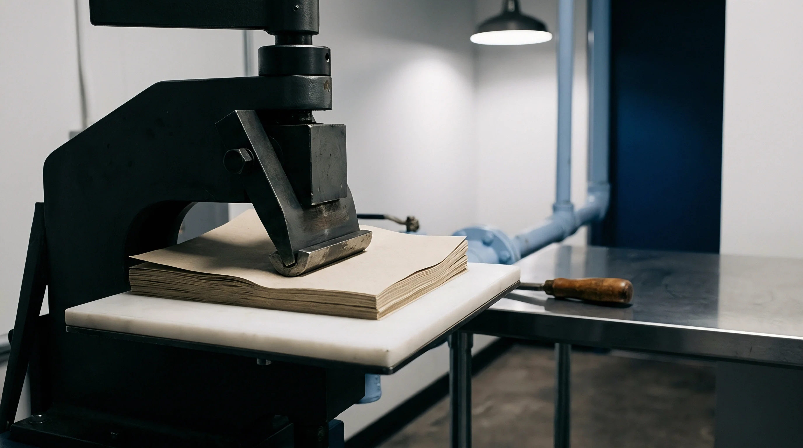
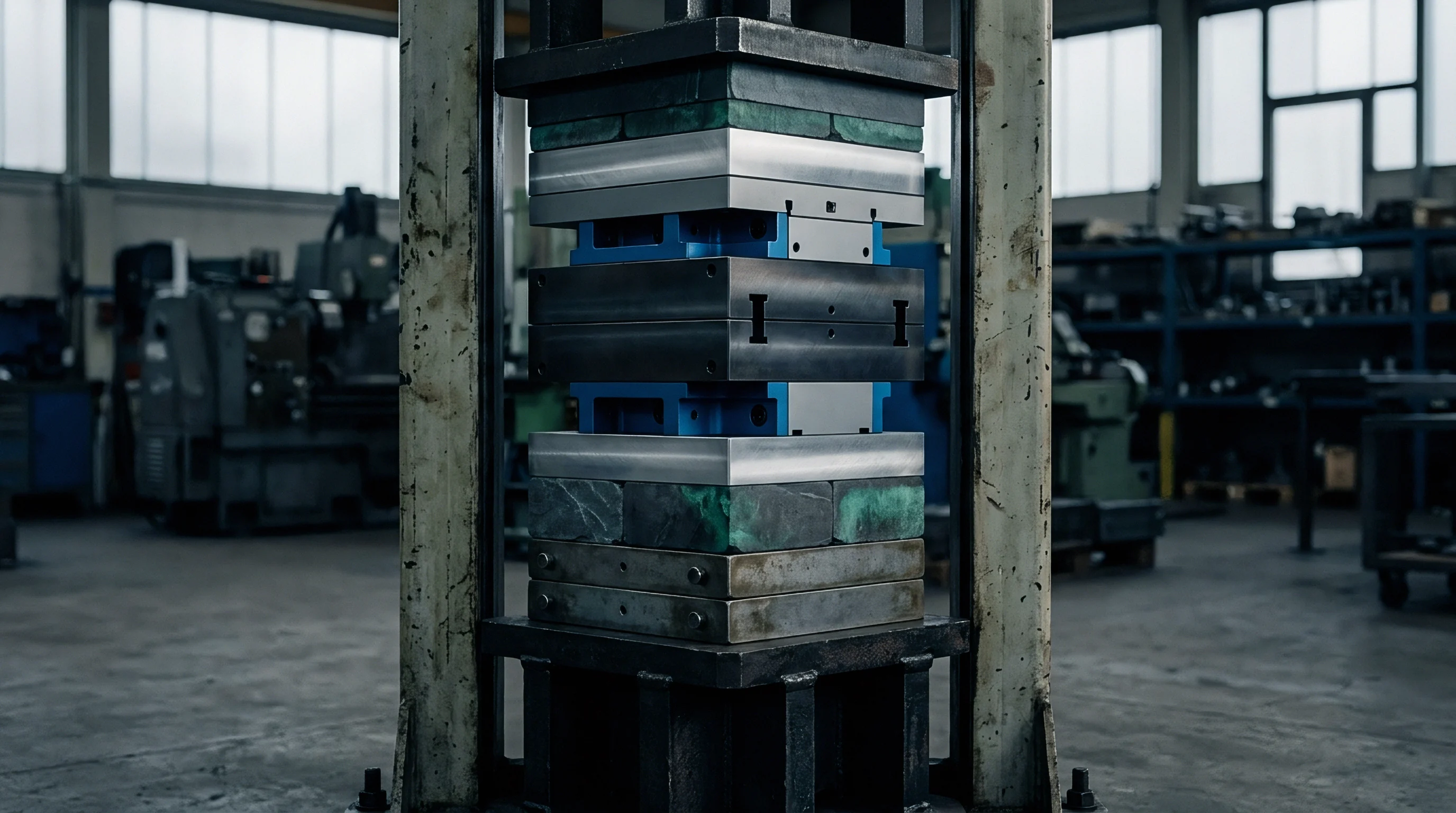
Female channel geometry establishes the spatial pocket into which paperboard and barrier laminate deform during die-cutting. When a male scoring element strikes the surface of a barrier-coated paperboard, stress concentrations gather along the fold axis. In flatbed die-cutting, matrix channels made of phenolic resin or pressboard establish the outer boundaries of this flexural crease.
In rotary systems, milled steel counter-cylinders perform this exact spatial role. Channel width determines outer ply strain. Expanding female channel dimensions prevents mechanical shearing along polymer skin layers during folding operations.

Matrix Width and Depth Mechanics
Channel width calculation traditionally relies on standard formulas adding double sheet thickness to rule thickness. With extrusion-coated polyolefins or metallized PET barrier layers, standard spacing produces severe shear stress at the shoulder of the matrix. The outer barrier film undergoes tensile expansion as the score line forms.
Milled steel counter-cylinders perform this role. Increasing channel width by ten to fifteen percent beyond standard cartonboard recommendations expands the strain distribution zone across a wider surface area. This adjustment drops localized peak elongation in the polymer membrane, mitigating micro-crazing without diminishing crease folding memory.
Polymer film tension inside female matrix channels exceeds elongation limits when channel depth drops below eighty percent of total board thickness.
Counter-Plate Profiles for Extrusion Coatings
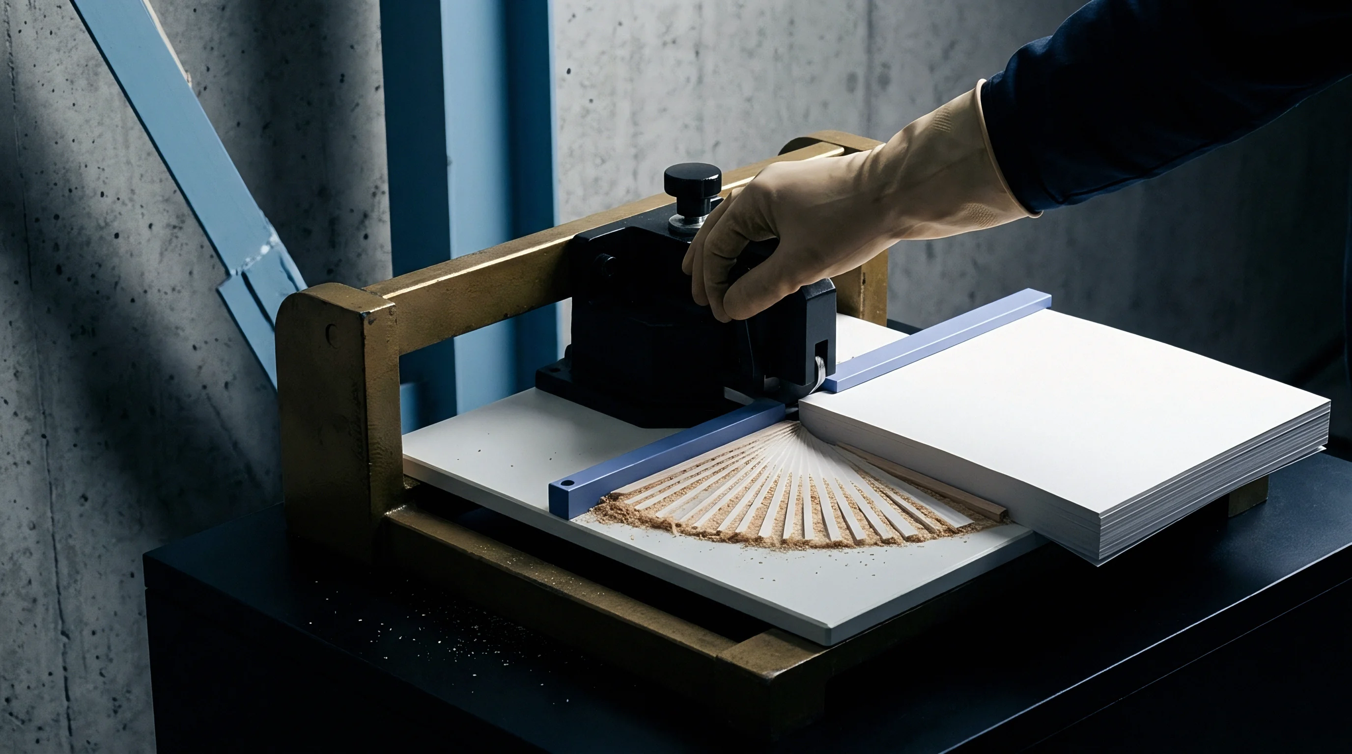
Steel counter-plates provide rigid tolerances required for high-speed long-run converting lines. Milling precise channels into hardened steel eliminates the dimensional drift common in stick-on matrix channels under elevated ambient temperature. Chamfering the channel edges with a fifteen-degree relief angle removes the sharp pivot point that slices thin ethylene vinyl alcohol copolymer layers.
Radiused channel shoulders allow smooth displacement of board fibers while protecting delicate dispersion barrier coatings from mechanical abrasion.
| Barrier Layer Type | Board Caliper (microns) | Standard Matrix Width Factor | Barrier Adjusted Matrix Width Factor | Channel Depth Ratio |
|---|---|---|---|---|
| Low-Density Polyethylene (LDPE) | 350 to 450 | 1.5 x Caliper + Rule Width | 1.7 x Caliper + Rule Width | 1.00 x Caliper |
| Ethylene Vinyl Alcohol (EVOH) Co-extrusion | 300 to 400 | 1.5 x Caliper + Rule Width | 1.8 x Caliper + Rule Width | 0.90 x Caliper |
| Metallized Polyethylene Terephthalate (mPET) | 250 to 350 | 1.4 x Caliper + Rule Width | 1.65 x Caliper + Rule Width | 0.85 x Caliper |
| Aqueous Dispersion Coating | 300 to 500 | 1.5 x Caliper + Rule Width | 1.75 x Caliper + Rule Width | 0.95 x Caliper |
Matrix suppliers often explain that pinhole formation stems entirely from substrate elasticity variations rather than inadequate matrix channel dimensions.

Stretch
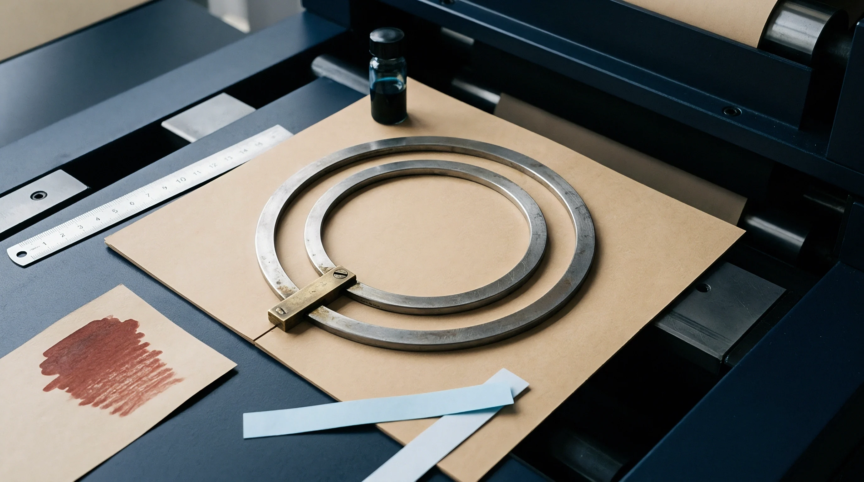
Polymeric barrier layers applied to paperboard experience severe elongation during score line forming and subsequent carton folding. Tensile forces acting on the outer radius of the bend force the film toward its yield point. Low-density polyethylene tolerates elongation values exceeding two hundred percent before structural rupture occurs.
High-barrier materials like aluminum foil or metallized polyester exhibit tensile limits below fifteen percent elongation. Pinholes form at peak tensile strain.
Polymer Layer Elongation Limits
Polymer crystalline structure governs strain behavior. Unoriented polyethylene coatings yield plastically, distributing stress across adjacent polymer chains. Cross-linked or highly crystalline polymers resist flow, concentrating tensile energy at micro-imperfections inside the coating layer.
Temperature inside the converting hall alters polymer ductility. Cold storage increases film cracking. Maintaining stock at twenty-two degrees Celsius with fifty percent relative humidity preserves intrinsic polymer flexibility during high-speed converting.
Conditioning paperboard at twenty-three degrees Celsius and fifty percent relative humidity maintains polymer film ductility within specified tensile limits.

Fiber Axis Orientation Influence
Paperboard flexural anisotropy directly dictates the tensile load transferred to the barrier film during creasing. Scores running parallel to the machine direction force fewer longitudinal fibers to bend, causing severe localized stress on the inner and outer coating plies. Scores perpendicular to the machine direction distribute the bending strain across cross-direction fibers, yielding a smoother bead formation.
Balancing score line geometry against web direction maintains consistent barrier preservation across complex carton blanks.
- Micro-pinholing occurs when localized elongation exceeds layer tensile limits, producing invisible micro-voids that raise oxygen permeation rates above baseline numbers.
- Delamination shear develops when poor tie-layer adhesion permits the barrier membrane to separate from the top paperboard liner during scoring displacement.
- Crazing networks form inside rigid dispersion coatings, creating fine spiderweb micro-cracks that degrade liquid barrier capacity under water column hydrostatic testing.
- Aluminum foil fracture happens along sharp score bends where inelastic metal foil cannot match paperboard fiber displacement, breaking electrical conductivity and vapor sealing.
Whether bio-based barrier polymers can achieve tensile yield matching conventional low-density polyethylene without compromising bio-degradation speed remains an open industry challenge.
Rule
Male scoring elements force paperboard fibers into female counter-channels to form a localized hinge structure. Standard creasing blades feature a round top radius designed to score untreated solid bleached sulfate or folding boxboard. When scoring sheets carrying thin barrier layers, sharp blade points or tight radii concentration forces cut directly into the polymer matrix.
Blade radius shifts contact surface area. Switching from standard two-point or three-point scoring steel to specialized rounded or modified profile geometry prevents top-layer perforation while maintaining clean double-line bead structure.
Tip Radius and Chamfer Profiling
Blade geometry modifications reduce surface shear force at the point of impact. A two-point blade measuring zero point seven one millimeters in thickness standardly carries a top radius of zero point three five millimeters. Chamfered edges prevent top liner shear.
Increasing the tip radius to zero point five zero millimeters creates a broader contact area, distributing impact pressure across wider fiber bundles. Beveled edges reduce sharp edge rubbing along score lines, preventing localized delamination between the board top liner and the extrusion coating layer.

Does Penetration Depth Alter Barrier Failure Thresholds?
Penetration distance into the board sheet dictates how far fibers shift into the matrix cavity before bottoming out. Excessive penetration compresses board layers to high density, forcing the top film coating into extreme tension. Setting penetration depth to sixty-five percent of overall substrate thickness prevents shearing of internal ply bonds while leaving the barrier skin unbroken.
Reducing stroke depth in flatbed platen presses by zero point zero five millimeters often restores full oxygen barrier values across creased carton samples.
A broader scoring tip radius distributes platen impact pressure over a larger substrate area, preventing localized film fracture.
Softening the top radius of male creasing steel consistently prevents thin coating layers from shearing during folding operations.

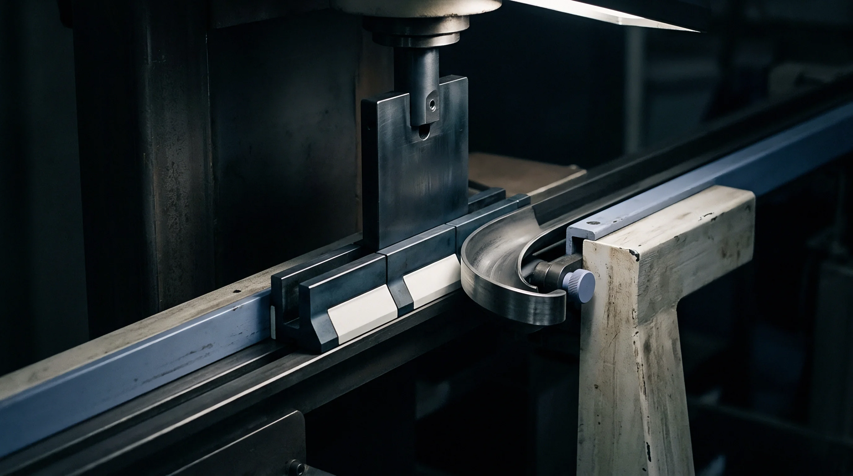
Caliper
Board thickness dimensions set the baseline for every creasing geometry calculation on die-cutting equipment. Variations in basis weight or board density across web widths alter how deep male scoring rules penetrate into female channels. Solid bleached sulfate, coated recycled board, and folding boxboard compress differently under identical die pressures due to distinct fiber furnish layers.
When board thickness surges unexpectedly during production runs, fixed-depth matrix channels produce over-compression, cracking delicate barrier films.
Substrate Thickness Compression Mechanics
Z-directional board compression absorbs a substantial portion of the scoring force before fiber shear occurs. Board compression absorbs scoring force. Dense sheets transfer force outward.
Low-density folding boxboard with bulky groundwood center plies compresses easily, requiring deeper matrix depth setting. High-density solid bleached sulfate resists thickness compression, transferring force directly outward to the surface barrier film. Tooling adjusted for bulky substrates will rupture thin barrier coatings when run on dense bleached kraft grades.
Internal Bond Strength and Ply Separation
Delamination within middle fiber plies provides necessary clearance for clean score folding without surface tearing. Standard TAPPI T 541 testing measures internal bond strength in kilopascals, defining how easily board layers separate internally under tension. Low internal bond strength allows center plies to delaminate smoothly, absorbing flexural displacement without stressing top-surface polyolefins.
High internal bond strength locks plies together, forcing the top barrier film to absorb all bending elongation, causing severe cracking.
- Substrate thickness verification confirms batch caliper consistency before die platen setup, ensuring channel depth calculations match delivered board physical properties.
- Dye stain penetration check verifies coating layer continuity immediately after first press impression, identifying micro-fractures before full speed production runs begin.
- Oxygen permeation baseline testing establishes precise oxygen transmission rate decay numbers on creased samples compared against flat sheets under controlled laboratory conditions.
- Matrix channel wear monitoring tracks female groove edge erosion across high-volume runs, preventing progressive pinholing caused by matrix shoulder sharpening.
| Paperboard Grade | Density (g/cm3) | Internal Bond (J/m2) | Compression Behavior | Tooling Adjustment |
|---|---|---|---|---|
| Solid Bleached Sulfate (SBS) | 0.80 to 0.90 | 180 to 240 | Low compressibility | Expand matrix channel width by 15 percent |
| Folding Boxboard (FBB) | 0.55 to 0.65 | 120 to 160 | High compressibility | Increase channel depth by 10 percent |
| Coated Recycled Board (CRB) | 0.70 to 0.80 | 100 to 140 | Moderate compressibility | Use radiused male rule tip of 0.71 mm |
| Uncoated Kraft Back (SUB) | 0.75 to 0.85 | 200 to 260 | Low compressibility | Apply 20 percent wider female channel |
Ignoring board thickness variation across batch shipments results in thousands of leaking barrier cartons entering commercial fill lines before discovery.
Arithmetic
Calculating precise matrix widths, matrix depths, and rule thickness values requires mathematical modifications specific to barrier-coated substrates. Standard die-cutting references provide simple empirical equations designed for plain un-laminated paperboard. Applying those baseline equations directly to barrier laminates causes structural cracking and barrier degradation.
Incorporating coating film thickness, tensile elongation coefficients, and substrate stiffness into matrix sizing equations protects barrier film performance across high-speed converting runs.
Die Sizing Equations for Barrier Film Integrity
Standard female channel width calculation follows the standard equation where channel width W equals male rule thickness t_r plus one point five times paperboard thickness t_b. For barrier-laminated board, the modified channel width equation applies:
W_barrier = t_r + (1.75 x t_b) + (2 x t_f)
where t_f represents the barrier film coating thickness in millimeters. Matrix channel depth D standardly equals board thickness t_b. For delicate barrier films like EVOH or metallized PET, channel depth is calculated using the modified equation:
D_barrier = 0.90 x t_b
Reducing depth by ten percent prevents excessive downward stretching of the top film ply into the bottom corners of the channel matrix during peak platen pressure.
Worked Example for a High-Barrier Packaging Spec
Consider a typical high-barrier board spec. Assume a packaging job specifies a 400-micron solid bleached sulfate board carrying a 25-micron EVOH co-extruded barrier layer, yielding a total substrate thickness of 0.425 mm, run with a 2-point male creasing rule measuring 0.71 mm in rule thickness.
Standard matrix width without barrier correction yields:
W_std = 0.71 + (1.5 x 0.425) = 1.3475 mm
Barrier-adjusted matrix width using the modified formula yields:
W_barrier = 0.71 + (1.75 x 0.400) + (2 x 0.025) = 1.460 mm
Standard matrix depth equals 0.425 mm. Barrier-adjusted matrix depth yields:
D_barrier = 0.90 x 0.400 = 0.360 mm
The adjusted matrix protects film continuity. The calculation reveals that standard matrix geometry yields a 1.35 mm width by 0.43 mm depth channel. The barrier-adjusted geometry specifies a 1.46 mm width by 0.36 mm depth channel.
Expanding channel width by 0.11 mm and reducing depth by 0.07 mm drops tensile strain below the EVOH cracking threshold.
- Measure total substrate thickness and individual barrier film thickness using ISO 534 micrometric methods prior to tooling setup.
- Calculate modified female matrix channel width using the barrier elongation coefficient formula.
- Select counter-plate channel depth corresponding to ninety percent of base board thickness.
- Install radiused male scoring rule featuring a zero point five zero millimeter crown tip.
- Perform initial test platen impression at fifty percent operating line speed to inspect bead geometry.
- Verify barrier film continuity using solvent dye stain penetration test ASTM F1929.
Tolerance Bands and Operational Adjustments
Holding precise die geometry on high-speed flatbed platen presses requires controlling die compression tolerances. Thermal expansion of die boards during six-hour continuous production runs can shift scoring centerlines by up to zero point zero eight millimeters. Table 3 illustrates how deviations in channel width alter gas transmission rate values post-folding.
| Matrix Channel Width (mm) | Channel Depth (mm) | OTR (cc/m2/day at 23C, 0% RH) | WVTR (g/m2/day at 38C, 90% RH) | Barrier Integrity Status |
|---|---|---|---|---|
| 1.30 (Undersized) | 0.42 | 45.2 | 12.8 | Severe Pinholing Failure |
| 1.35 (Standard) | 0.40 | 18.4 | 4.5 | Micro-crazing Detected |
| 1.46 (Barrier Optimized) | 0.36 | 0.8 | 0.3 | Zero Defects Preserved |
| 1.60 (Oversized) | 0.36 | 1.2 | 0.4 | Slight Board Flute Roll |
Standard ISO 12647 quality addendums now include maximum crease strain tolerances that obligate converters to certify zero oxygen barrier degradation post-folding.
Rejection
Quality control at goods-in and post-converting inspection catches structural barrier failures before finished packages enter retail supply chains. Non-destructive oxygen permeability testing, solvent dye creep checks, and helium leak detection isolate micro-pinholes caused by incorrect die geometry. Off-spec die setups increase scrap cost.
Identifying crease line fractures during initial press setup prevents whole-batch scrap incidents involving tens of thousands of printed carton blanks.
Testing Procedures for Crease Line Integrity
Dye penetration testing under ASTM F1929 provides immediate physical evidence of coating rupture along fold lines. Dye staining exposes micro-cracks quickly. Lab testing quantifies gas leakage rates.
Applying a colored glycol solvent dye along the score line reveals micro-cracks within thirty seconds if the barrier film has broken. Oxygen transmission rate measurements performed according to ASTM D3985 on creased carton samples quantify gas leakage in cubic centimeters per square meter per day. Comparing flat un-creased board values against folded sample values establishes the exact barrier retention percentage of the die setup.
Commercial Exposure and Cost Calculations
Delivering compromised barrier packaging to food or pharmaceutical brand owners triggers costly commercial liabilities. A single production run of one hundred thousand defective liquid packaging cartons discarded at filling plants represents direct stock waste, press time loss, and freight claims. Table-based die geometry checks prevent systematic pinholing across entire production runs.
A ten percent jump in oxygen transmission rate across folded scores marks the operational threshold for immediate creasing matrix replacement.
Tooling adjustments grounded in substrate mechanics protect product shelf life while keeping converting waste within standard budget allowances.