Matrix Channel Width Calibration for Matte Co-Extruded Film Converting
Calibrating matrix channel width to rule thickness plus 1.6 times composite caliper prevents matte skin fracture on co-extruded film laminated paperboard.


Skin
A matte co-extruded film surface fractures along the crease line when internal tensile stress exceeds the yield strength of its unoriented matte surface layer. On the converting floor, standard gloss film stretches under a 2-point creasing rule, but matte co-extruded film behaves differently. Its matte effect comes from a specialized skin layer ~ typically made by blending incompatible polymers like polypropylene with polyethylene terephthalate domain inclusions, or through heavy inorganic particulate loading with talc or synthetic silica.
This skin layer has a lower elongation at break than the core resin underneath. As it enters the matrix channel, the outer skin undergoes immediate localized elongation while the ductile core deforms elastically, creating a sharp shear gradient across the film caliper.
Co-extruded films require a different calibration than solid biaxially oriented polypropylene laminates. A standard three-layer matte film consists of a thin matte skin layer, a structural core, and a heat-sealable or adhesive-receptive backing layer. The matte skin is between 1.5 and 3.5 microns thick, while the core provides the film web’s tensile strength.
When a creasing rule forces the composite sheet into the matrix channel, peak tension hits the outer radius of the fold. Matting agents within the skin layer act as stress concentrators, so micro-voiding begins at just three percent elongation. If channel width is set using standard paperboard formulas, the outer skin fractures, leaving a visible white haze or an actual fiber-exposure line along the finished crease.

Surface Energy Dynamics and Interfacial Shear
Adhesion between the co-extruded film and the paperboard substrate determines whether stress distributes evenly or concentrates at a failure point. Corona or flame treatment raises the surface energy of the bonding side to between 38 and 44 mN/m, measured by ISO 8296 wetting tension test methods. When bonding the film to bleached sulphate board using solventless polyurethane or extrusion-coated ethylene-vinyl acetate adhesives, the adhesive layer serves as a shock absorber during rule impact.
An adhesive with a high storage modulus transfers shear forces directly into the matte skin, whereas a more compliant adhesive permits micro-slippage at the interface, protecting the surface from elongation spikes as it seats into the female channel.
Stylus profilometry measures the surface roughness of matte co-extruded films to link surface topography directly with crack propagation. Peak-to-valley height measurements show that deeper surface valleys in high-matte formulations initiate micro-cracks at lower folding radii. When a 2-point rule pushes a 450-micron laminated board into a matrix groove, outer surface bending strain follows classic beam theory, modified for non-linear plastic deformation of the board matrix.
If the skin cannot sustain that calculated flexural strain, cracks propagate inward to the polyolefin core, causing full lamination splitting during high-speed folding and gluing.
Peak flexural strain across a 1.8-millimeter matrix channel causes instant micro-voiding in silica-filled skin layers when surface elongation exceeds 4.2 percent under ambient conditioning at 23 degrees Celsius and 50 percent relative humidity.
Board grain direction amplifies surface failure when matrix channel widths run narrow. Folding boxboard bent cross-grain presents higher compressive resistance inside the crease channel, forcing more of the system’s total displacement into the outer matte film skin. Parallel-grain folding reduces compression resistance on the reverse side, letting the board matrix collapse into the female groove without over-stretching the matte layer.
Press operators must account for this anisotropy by adjusting channel widths separately for cross-grain and long-grain scores on the same sheet layout.
Temperature variations on the press floor alter skin ductility. At ambient temperatures below 18 degrees Celsius, polyolefin skin layers lose impact strength and tend to fracture brittly during matrix entry. Thermally conditioning master rolls prior to die-cutting stabilizes elongation parameters.
Maintaining converting room environments within controlled thermal bands keeps skin ductility predictable across shifts and seasonal cycles.
The film’s core layer retains structural integrity even when the matte skin develops micro-fractures. This creates an aesthetic defect that fails visual quality standards long before the pack loses mechanical strength. White haze along score lines degrades print contrast on dark matte packaging, causing customer rejections despite intact barrier properties.
Precise channel width selection is the primary defense against micro-fracturing.
How far can matte skin elongation be extended through formulation changes without forfeiting the low-gloss measurement required by visual pack specifications?

Groove
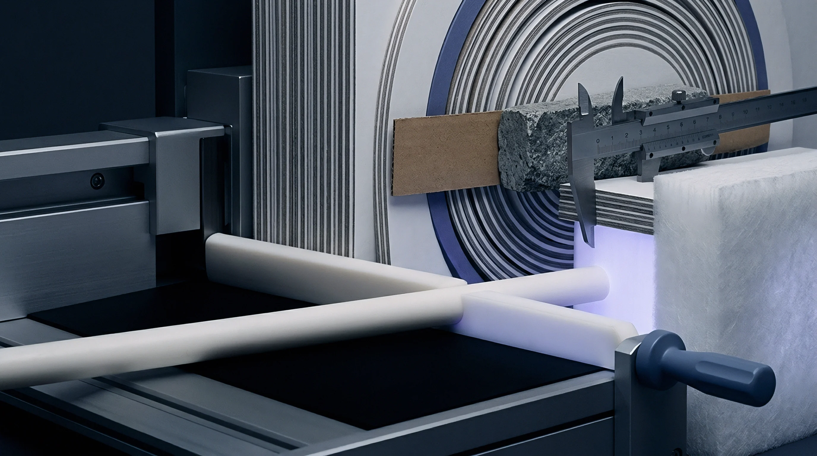
Matrix channel width governs the clearance space for the board and film laminate as the creasing rule reaches full stroke depth. Standard paperboard calculations rely on a baseline formula: channel width equals creasing rule thickness plus 1.4 times total substrate thickness. Applying this ratio to matte co-extruded film laminates causes immediate score line cracking.
The extra volume from the elastic film, coupled with high friction between the matte skin and matrix walls, demands wider clearance. Preventing film shear requires adding an adjustment factor to the channel width equation.
The revised equation sets channel width equal to rule thickness plus 1.6 times the combined caliper of board, adhesive, and film, plus a dedicated skin clearance constant. This expanded geometry leaves room for the double-layer film bulge formed as the substrate folds into the channel. Without the extra width, the female matrix shoulder pinches the outer film against the creasing rule edge, cleanly slicing the skin along the outer crease boundary.

Geometrical Formulations for Channel Calibration
Selecting matrix channel depth requires equal care. Depth must match the compressed thickness of the laminated board ~ total caliper minus internal void collapse under die pressure. A channel that runs too deep lets the board sink without forming a defined internal bead, yielding a loose crease with high fold resistance.
A channel that runs too shallow crushes board fibers, ruining the structural stiffness of the finished crease while stretching the matte film over an overly sharp female shoulder radius.
The interaction between the creasing rule profile and the matrix shoulder radius dictates the strain rate applied to the film. Standard rules feature a fully rounded head profile. For matte film laminates, a modified broad-crown or double-eccentric profile distributes initial contact pressure across a wider surface area.
This reduces point stress on the matte skin, allowing the film to glide smoothly into the channel without localized necking.
| Substrate Caliper (mm) | Film Type & Caliper | Rule Thickness (pt / mm) | Standard Width Formula (mm) | Calibrated Matte Width (mm) | Optimal Depth (mm) |
|---|---|---|---|---|---|
| 0.350 | 18 µm Matte Co-Ex OPP | 2 pt / 0.71 mm | 1.20 | 1.30 | 0.40 |
| 0.400 | 18 µm Matte Co-Ex OPP | 2 pt / 0.71 mm | 1.27 | 1.38 | 0.45 |
| 0.450 | 20 µm Matte Co-Ex PET | 2 pt / 0.71 mm | 1.34 | 1.46 | 0.50 |
| 0.500 | 20 µm Matte Co-Ex PET | 3 pt / 1.07 mm | 1.77 | 1.92 | 0.55 |
| 0.600 | 25 µm Matte Co-Ex PE | 3 pt / 1.07 mm | 1.91 | 2.08 | 0.65 |
Female matrix walls built with sharp 90-degree internal corners induce severe shear along the outer film boundary at full stroke. Modern channels designed for sensitive films feature chamfered or rounded shoulder entry zones. A shoulder radius between 0.2 and 0.4 millimeters on the groove entry edge cuts frictional drag as the film enters the channel, preserving skin integrity across long converting runs.
- Shear skinning line failure occurs when an undersized matrix width pinches the matte film directly against the steel creasing rule edge during full platen stroke.
- Delamination blister formation develops when matrix depth is too shallow, forcing internal ply separation to migrate laterally past the crease shoulders.
- Crease line whitening stems from micro-fractures in the filled matte skin caused by excessive edge tension over unrounded matrix groove shoulders.
- Roll-back bead distortion happens when matrix channel clearance is excessive, preventing crisp score line definition and driving up folding torque.
Matrix selection must account for sheet thickness variations across master paperboard rolls. Mill tolerances commonly allow a plus-or-minus four percent variance in caliper. On a 500-micron substrate, a twenty-micron increase in caliper reduces effective channel clearance by over ten percent if matrix sizing remains static across the cutting plate.
Operators should calibrate matrix channels to the upper limit of the mill caliper tolerance band to prevent sporadic film fracturing during high-speed runs.
Channel width selection dictates the precise geometric boundary between controlled internal fiber displacement and destructive surface skin rupture.
Channel alignment relative to the rule centerline demands absolute precision. A lateral offset of just 0.05 millimeters between rule center and channel center disrupts the clearance balance ~ turning one side of the crease into a high-shear pinching zone while the other lacks formation pressure. Laser-guided location channels eliminate offset errors during make-ready, protecting sensitive matte skins from asymmetric damage.
Matrix width calibration always expands when moving from gloss film laminates to matte co-extruded structures on identical board calipers.

Pressboard
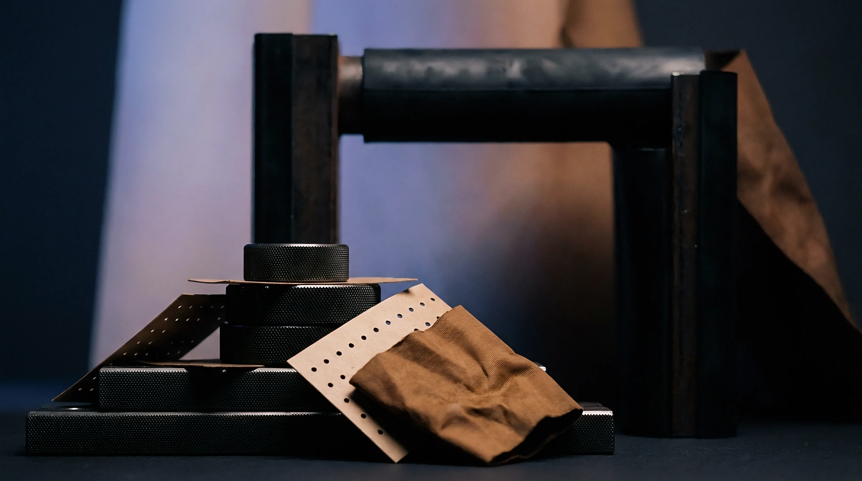
Matrix composition dictates dimensional stability under repeated platen impact. Pressboard matrices made from high-density resin-bonded cellulose fibers offer low thermal expansion and clean milling, fitting medium-length runs. But under continuous press speeds exceeding 7,500 impressions per hour, paper-based matrix walls gradually compress and mushroom outward.
This deformation narrows effective entry width while reducing groove depth, systematically degrading crease quality as the shift wears on.
Extruded synthetic matrix channels made from modified polyvinyl chloride or high-impact polymers offer superior resistance against lateral crushing. Plastic matrices maintain accurate shoulder radii across runs exceeding 100,000 impressions. For matte co-extruded films, the smooth finish of extruded polymer channels lowers friction as the skin slides into the groove, minimizing localized elongation and preserving surface texture during rapid insertion.
Why Does Co-Extruded Skin Delaminate during Score Penetration?
Skin delamination occurs when the peel force from matrix adhesive backing exceeds the bond between film and paperboard, or when internal tension overcomes interfacial bonding between co-extruded layers during channel extraction. As the platen opens and the rule retracts, the formed crease springs back out of the groove. If channel shoulders carry sticky adhesive residue or high friction, the film temporarily clings to the channel wall, pulling the skin away from the adhesive layer and forming micro-delamination bubbles along the score line.
Steel counter-dies milled from solid spring-steel plates eliminate wall flexure entirely. They maintain exact channel geometry across millions of cycles, making them the benchmark for high-volume converting. Milled channels feature polished entry radii that eliminate surface drag, though steel counters demand perfect platen parallelism and rigid tooling ~ a minor setup misalignment will destroy creasing rule edges against the hardened steel plate.
| Matrix Material Class | Dimensional Stability | Friction Coefficient (vs Matte Film) | Maximum Run Life (Impressions) | Relative Tooling Cost Factor |
|---|---|---|---|---|
| Resin-Bonded Pressboard | Moderate (Wall flex under load) | 0.35 – 0.42 static | 40,000 | 1.0 (Baseline) |
| Extruded Polymer (PVC) | High (Resists lateral compression) | 0.22 – 0.28 static | 150,000 | 1.8 |
| Phenolic Laminated Fiber | Very High (Minimal deflection) | 0.28 – 0.32 static | 300,000 | 3.2 |
| Milled Steel Counter-Die | Absolute (Zero deflection) | 0.15 – 0.18 static | 2,000,000+ | 8.5 |
Locating tape performance governs matrix shear stability during continuous converting. The adhesive backing securing the matrix strip to the cutting plate must withstand high dynamic shear without creeping. Under repetitive strikes, lower-grade acrylic adhesives suffer from cold flow, allowing the channel to shift up to 0.15 millimeters laterally over a shift.
This drift alters calibration, causing sudden film cracking on the side starved of clearance.
ISO 12647-7 graphic technology guidelines require score line cracking evaluations to be conducted under standardized 50-diopter magnification to identify microscopic skin separation before visual haze failure becomes apparent to the naked eye.
Base tape thickness adds directly to total matrix depth. Make-ready foremen often overlook the 0.05 to 0.08 millimeter tape layer when calculating channel depth. Omitting it leaves the effective groove sitting higher off the plate, leading to over-impression on the board reverse side and premature splitting of the matte skin.
Surface haze along score lines can stem from inadequate film treatment at the lamination plant rather than matrix shoulder friction.

Dwell
Press calibration requires a methodical setup to establish correct impression pressure without crushing substrate caliper. Make-ready begins with a leveling pass to ensure absolute parallelism between the die chase and cutting plate. Once confirmed, impression force is raised incrementally until creasing rules reach full penetration depth.
Over-impression is the single largest cause of score line failure in matte film converting: excess tonnage forces the rule past its calculated stroke, crushing the board to absolute density and slicing through the outer film.
Operating speed introduces a critical variable: dwell time ~ the duration the creasing rule stays at maximum stroke depth inside the matrix channel. At 3,000 sheets per hour on a flatbed autoplaten, dwell time ranges from 40 to 60 milliseconds. At 9,000 sheets per hour, it drops below 15 milliseconds.
Because polyolefins are viscoelastic, shorter dwell times raise the effective elastic modulus, making the matte skin behave in a stiffer, more brittle fashion during rapid displacement.

Step-by-Step Press Calibration and Bring-Up Protocol
To establish calibrated matrix conditions on press, operators follow a strict mechanical setup sequence. Skipping steps or relying on visual estimation inevitably drives up scrap rates.
- Verify cutting platen parallelism using carbon impression sheets set at zero cutting pressure across all four plate quadrants.
- Mount the laser-cut dieboard into the chase and secure it to torque limits to prevent warping or frame displacement.
- Clean the ground steel cutting plate thoroughly with solvent degreaser to remove residual oil, anti-setoff powder, and adhesive traces.
- Apply self-adhesive matrix strips to the creasing rules using central locator channels to guarantee alignment across every knife path.
- Peel protective backing from the matrix tape and lower the die chase to transfer the strips cleanly onto the steel cutting plate.
- Remove locator channels carefully, checking each strip visually to confirm no adhesive residue remains inside the female matrix groove.
- Run a trial sheet at minimum impression tonnage, gradually increasing platen pressure in 0.05-millimeter increments until a full score bead forms.
- Inspect cross-sectioned sample folds under a measuring microscope to verify zero film splitting and correct internal ply separation before releasing full-speed production.
Dynamic compression of matrix shoulders under high-speed operation requires operators to adjust impression settings once the machine reaches thermal equilibrium. Friction warms the cutting platen during the first 30 minutes of a run, expanding the steel bed by up to 0.03 millimeters. This growth increases effective creasing pressure, shifting a calibrated setup into an over-compressed state that tears matte film skins.
Increasing platen pressure to force a dull cutting rule through heavy board accidentally sheared the matte film skin across twenty-four die cavities on a luxury cosmetic packaging run.
Crease stiffness testing verifies whether calibration achieves target fold resistance without over-stressing the film web. A 15-degree crease resistance tester following ISO 5628 methods measures the force required to bend the formed score line. A correctly calibrated matrix yields a smooth bend resistance curve with a low peak bending moment.
An improperly calibrated channel creates a high initial resistance peak followed by a sharp drop in force, signaling that the matte skin or outer board plies fractured during folding.
Score lines must be inspected under both directional key-lighting and diffuse illumination. Directional light exposes micro-cracks along outer crease shoulders, while diffuse light highlights subtle color shifts or hazing from localized stretching. Integrating automated optical inspection directly on folding-gluing lines enables continuous quality monitoring, flagging skin fractures before finished cartons reach customer packing lines.


Calculation
Analyzing a representative production job illustrates the mathematical method for calibrating matrix channel width and depth. Consider a personal care packaging project specifying 350 gsm premium folding boxboard laminated with an 18-micron matte co-extruded polypropylene film. To start, physical calipers of all components are measured following ISO 534 procedures.
The unlaminated paperboard has a caliper of 0.480 millimeters (480 microns). The solventless polyurethane adhesive layer adds 0.002 millimeters (2 microns). The 18-micron matte co-extruded OPP film comprises a 14-micron core layer and a 4-micron silica-filled matte skin layer.
Summing these gives a total composite caliper (Tc) of 0.500 millimeters. Because board grain runs parallel to the main display panels, the die-cut layout requires calculations for both cross-grain and long-grain scores.
Mathematical Derivation of Matrix Parameters
Selecting creasing rule thickness is the first step. For a composite caliper of 0.500 millimeters, standard guidelines call for a 2-point creasing rule with a nominal thickness (tr) of 0.71 millimeters. Using the expanded matte co-extruded formula, matrix channel width (W) is calculated as follows:
W = tr + (1.6 × Tc) + Cs
Where Cs represents the matte skin clearance constant, set at 0.05 millimeters for films containing particulate matting agents with low elongation limits. Substituting the measured values into the formula yields:
W = 0.71 mm + (1.6 × 0.500 mm) + 0.05 mm = 0.71 mm + 0.80 mm + 0.05 mm = 1.56 mm
Matrix channel depth (D) comes from calculating compressed substrate thickness under impression. Folding boxboard compresses by roughly 15 percent under proper scoring pressure without structural collapse. Channel depth therefore equals total caliper multiplied by the residual thickness factor:
D = Tc × (1 – 0.15) = 0.500 mm × 0.85 = 0.425 mm
Commercial matrix channels are produced in discrete depth increments of 0.05 millimeters. The calculated depth of 0.425 millimeters points to a 0.40 millimeter matrix depth, avoiding over-impression on the reverse side while accounting for the extra 0.05 millimeter elevation from the tape backing layer.
| Parameter Description | Variable Symbol | Raw Value | Calculation Formula | Final Calibrated Value |
|---|---|---|---|---|
| Base Board Caliper | Tb | 0.480 mm | Measured via ISO 534 | 0.480 mm |
| Adhesive Layer Caliper | Ta | 0.002 mm | Applied dry coat weight | 0.002 mm |
| Matte Film Caliper | Tf | 0.018 mm | Nominal web thickness | 0.018 mm |
| Composite Caliper | Tc | 0.500 mm | Tb + Ta + Tf | 0.500 mm |
| Creasing Rule Thickness | tr | 2 point | Standard die-making rule | 0.710 mm |
| Matte Skin Clearance | Cs | Constant | Empirical skin allowance | 0.050 mm |
| Target Channel Width | W | Calculated | tr + (1.6 × Tc) + Cs | 1.560 mm (Select 1.60 mm) |
| Target Channel Depth | D | Calculated | Tc × 0.85 minus tape | 0.400 mm (Commercial standard) |
| Cross-Grain Width Boost | Wcg | Calculated | W + 0.10 mm | 1.700 mm |
For cross-grain scores on the same layout, higher compression resistance requires broadening the channel by an additional 0.10 millimeters. The cross-grain channel width (Wcg) increases to 1.66 millimeters, rounding up to the nearest commercial matrix size of 1.70 millimeters. Using a uniform 1.56 millimeter channel across all positions would yield clean long-grain scores but cause immediate skin cracking on cross-grain folds.
- Establish true composite caliper by measuring the cured, laminated web rather than relying on unlaminated paperboard mill specifications.
- Separate long-grain and cross-grain scoring rules on the dieboard to assign matrix widths independently for each orientation.
- Subtract matrix backing tape thickness from calculated depth formulas to keep impression geometry within tight limits.
- Inspect first-off sheets under magnification across every die cavity before releasing the production run for full-speed execution.
Calculated dimensional calibrations remain valid only while raw material thickness properties stay within verified mill specification bands.
Failing to recalibrate channel width when switching film suppliers creates severe quality risks. Substituting a 15-micron matte PET film for an 18-micron co-extruded matte OPP film changes both thickness balance and elongation behavior. PET skins have higher tensile strength but much lower elongation limits than polyolefin skins, requiring an extra 0.05 millimeter in channel width to prevent score whitening despite the thinner overall film caliper.
Standard converting purchase contracts stipulate that score line cracking disputes are evaluated strictly against agreed dimensional matrix calibration dossier logs maintained during run bring-up.
Yield
Extended Producer Responsibility programs and evolving European packaging regulations impose financial penalties on structures that complicate fiber recovery. Laminated containers undergo strict recyclability testing following CEPI harmonized laboratory methods. During repulping, the co-extruded film must separate cleanly from cellulose fibers without shattering into micro-plastics that blind mill screen plates.
An over-compressed, fractured crease drives film shreds deep into the board core, anchoring plastic particles to damaged fibers and lowering total repulping yield.
Matrix channel calibration directly affects fiber yield during post-consumer recycling. When a score forms cleanly without rupturing inner board plies or outer film skin, the film stays continuous during mechanical hydrapulping. The intact film web separates easily from the slurry on screen plates, allowing recovery of over 98 percent of available cellulose fibers.
If an ill-calibrated matrix channel fractures the film along every edge, repulping breaks the film into tiny shreds, dropping fiber yield and triggering plastic contamination surcharges under eco-modulation fee schedules.

Commercial Mechanics and Run Cost Integration
Unit production costs hinge on setup precision and make-ready efficiency. A miscalibrated matrix that cracks matte skins consumes press time without generating billable output. On a die-cutting line operating at 180 euros per hour, spending two hours troubleshooting score line failure on press adds 360 euros in direct labor costs.
Spoiled setup sheets add another 150 euros per thousand, rapidly eroding margins on medium-run jobs.
Precision matrix tooling is a minor fraction of job expenditure, yet it dictates overall line profitability. Upgrading from standard pressboard matrix channels at 1.50 euros per meter to synthetic channels or steel counter-dies raises tooling costs slightly while delivering substantial operational savings over long runs. Eliminating score-related press stops and micro-cracks allows die-cutters to run at maximum rated speeds, boosting net shift output by up to twenty percent.
Specifying matte co-extruded film lamination requires explicit agreement between brand owner, converter, and tooling vendor on crease performance standards. Finish specifications that omit matrix calibration parameters leave converters vulnerable to defect claims. A solid purchase docket defines composite caliper, channel width and depth, allowable crease torque ranges, and the exact test protocols used to evaluate score line integrity.
The landed cost of matte film packaging balances material expenses against press speed, tooling spend, scrap allowances, and end-of-life recycling fees. Converting engineers who master matrix channel calibration prevent surface micro-fractures, keep presses running at full capacity, and ensure finished packages satisfy both visual brand standards and circular economy rules.