Paperboard Creasing Channel Calculation Methods
Calculate creasing channel width by multiplying board caliper by 1.5 for FBB or 1.6 for CRB, then adding rule thickness to prevent liner cracking.


Geometry

Mathematical Foundations of Width Calculation
Precision die-cutting relies on establishing an internal shear plane within paperboard layers without fracturing the top liner. When the creasing rule forces substrate material into a counter-matrix channel, the board undergoes localized delamination across its internal plies. The primary calculation for creasing channel width balances the rule thickness, board caliper, and machine-direction stiffness parameters.
Standard empirical calculations established under ISO 187 conditioning (23 °C, 50 percent relative humidity) calculate channel width by multiplying board thickness by a substrate coefficient and adding the physical thickness of the steel creasing rule.
For folding boxboard (FBB) and solid bleached board (SBB), the standard formula for creasing channel width defines width (W) as:
W = (1.5 × t) + tr
In this equation, t represents board caliper in millimeters and tr defines the creasing rule thickness in millimeters. Standard point sizes for die-cutting rules convert to metric values where 1.5 Point equals 0.53 mm, 2 Point equals 0.71 mm, 3 Point equals 1.05 mm, and 4 Point equals 1.42 mm. When calculating channel width for a 400 micron (0.40 mm) folding boxboard using a 2 Point (0.71 mm) rule, the resulting matrix width target measures 1.31 mm.
Conditioning paperboard at 23 °C and 50 percent relative humidity establishes baseline moisture equilibrium before measuring caliper for matrix width calculations.
Cross-direction creases demand wider channels than machine-direction creases due to the alignment of cellulose fibers. Fibers running parallel to the crease line offer less mechanical resistance, allowing tighter channel dimensions without surface tearing. Creases running transverse to the fiber orientation experience higher bending resistance, requiring an expanded multiplier of 1.7 to 1.8 applied to the board caliper to prevent top liner bursting during high-speed carton folding.

Rule Thickness Selection Protocols
Selecting rule thickness depends on substrate caliper thresholds and carton structural geometry. Calipers under 0.50 mm utilize 2 Point (0.71 mm) creasing rules to execute sharp, low-resistance folds. Calipers ranging from 0.50 mm to 0.80 mm require 3 Point (1.05 mm) rules, distributing force over a broader area to eliminate scoreline fracturing.
Substrates exceeding 0.80 mm caliper demand 4 Point (1.42 mm) rules, preserving crease integrity across heavy display cartons and multi-ply substrates.
- Verify raw sheet caliper across five locations on the master sheet using a dead-weight micrometer under ISO 534 test parameters.
- Identify fiber direction relative to main box fold lines using tearing or bending resistance tests.
- Apply the 1.5 multiplier for machine-direction scores and 1.7 for cross-direction scores against measured thickness.
- Add the measured steel rule thickness to determine theoretical minimum channel width.
- Select the nearest commercial matrix width rounding up to the closest standard manufactured channel size.
Applying tighter channel widths than derived calculations permit increases press load requirements while crushing board edges. Excess channel width allows the substrate to slip without forming a structured internal bead, creating erratic folding angles on automatic high-speed cartoning machinery.
Shorter rule height offset relative to cutting knife height regulates initial penetration depth across counter plate channels.


Groove
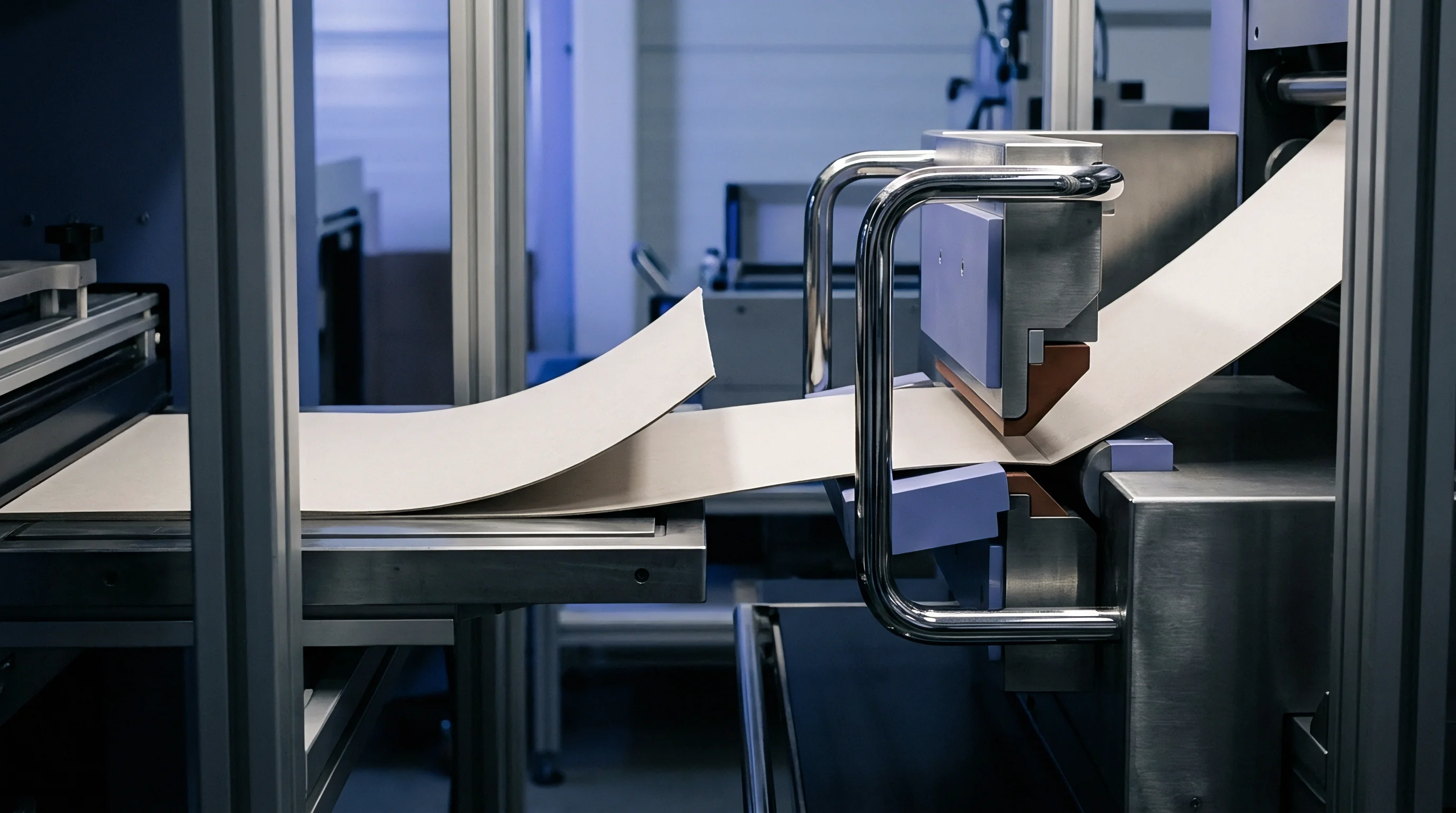
Matrix Depth Formulas and Board Compression
Channel depth dictates the volume allocated for the creased board bulge, known as the male bead, underneath the sheet. Selecting channel depth follows a direct relationship with substrate thickness. Matrix depth (D) equals nominal board caliper (t) for standard virgin fiber substrates.
Recycled grades possessing lower internal bond strength require a depth reduction of 10 percent to compress plies firmly without shear destruction.
Calculating parameters across common substrate classes requires adjusting baseline formulas to account for ply composition and density variations.
| Substrate Grade | Caliper Range (mm) | Rule Thickness (Pt / mm) | Channel Width Formula | Channel Depth Formula |
|---|---|---|---|---|
| Solid Bleached Board (SBB) | 0.30 – 0.60 | 2 Pt / 0.71 mm | W = (1.4 x t) + 0.71 | D = 1.0 x t |
| Folding Boxboard (FBB) | 0.35 – 0.80 | 2 Pt to 3 Pt | W = (1.5 x t) + t_r | D = 1.0 x t |
| Coated Recycled Board (CRB) | 0.40 – 0.90 | 3 Pt / 1.05 mm | W = (1.6 x t) + 1.05 | D = 0.9 x t |
| Coated Unbleached Kraft (CUK) | 0.45 – 1.00 | 3 Pt to 4 Pt | W = (1.7 x t) + t_r | D = 1.0 x t |
Consider a press run running a 0.55 mm caliper Coated Recycled Board (CRB). Using a 3 Point rule (1.05 mm), the calculated channel width equals (1.6 × 0.55) + 1.05 = 1.93 mm. The calculated channel depth equals 0.9 × 0.55 = 0.495 mm.
The converter matches these figures to a standard commercial matrix sized at 0.50 mm depth by 1.90 mm width, maintaining tolerance parameters within target operating thresholds.
Phenolic resin counter plates milled on CNC tables execute precise groove profiles unmatched by PVC strip matrix systems. Milled counter plates preserve sharp channel shoulders, preventing shoulder breakdown during long production runs exceeding 100,000 impressions. Strip matrix products utilize plastic walls mounted on flexible steel bases, subject to lateral deformation under continuous platen impact.
Matrix suppliers frequently claim that universal channel sizes accommodate wide caliper bands without sacrificing creasing quality.


Fiber

Substrate Behavior and Shear Forces
Substrate morphology determines how internal plies separate under impact. Solid Bleached Board composed of long, virgin softwood fibers tolerates significant deep shear strain, forming uniform internal delamination along the score axis. Middle plies of Folding Boxboard contain mechanical pulp fibers, providing high bulk but reduced tensile elasticity.
Coated Recycled Board contains short, multi-recycled fibers along with mineral fillers that limit internal shear displacement.
Delamination failure on die-cut paperboard manifests through distinct physical symptoms during folding operations.
- Liner Splitting occurs when channel width remains overly narrow, concentrating bending tension on the outer printed liner.
- Bead Crushing indicates excessive channel depth, preventing proper matrix compression against the lower ply layer.
- Shear Rupture develops when cross-direction rule forces sever short-fiber plies rather than separating them cleanly.
- Double Creasing emerges from wide matrix channels allowing board drift during rule impression cycles.
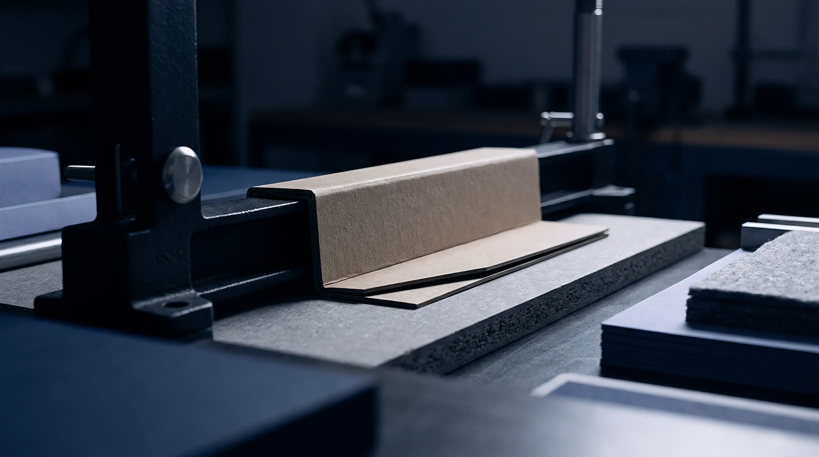
What Dictates Crease Delamination in Recycled Board?
Recycled fiber furnish exhibits lower Z-direction tensile strength compared to virgin fiber substrates. Measured according to ISO 1924 parameters, recycled plies lack the structural inter-fiber bonding necessary to withstand severe localized deflection. Matrix calculations for recycled boards incorporate a wider width multiplier, expanding the deflection zone to distribute shear stress over a larger substrate volume.
Relative humidity shifts on the converting floor alter board moisture content, altering crease performance mid-run. Moisture levels below 5 percent render cellulose fibers brittle, inducing immediate surface cracking along score lines. Moisture levels above 8 percent soften the sheet structure, causing weak bead formation and inconsistent folding resistance on high-speed gluer lines.
Standard ISO 5628 testing establishes that creasing reduces board bending stiffness along scorelines by 40 to 60 percent.
Whether mechanical treatment of recycled furnish can match virgin fiber creasing performance under low matrix clearance remains open to ongoing paper mill research.
Verification

Bench Testing and Quality Protocols
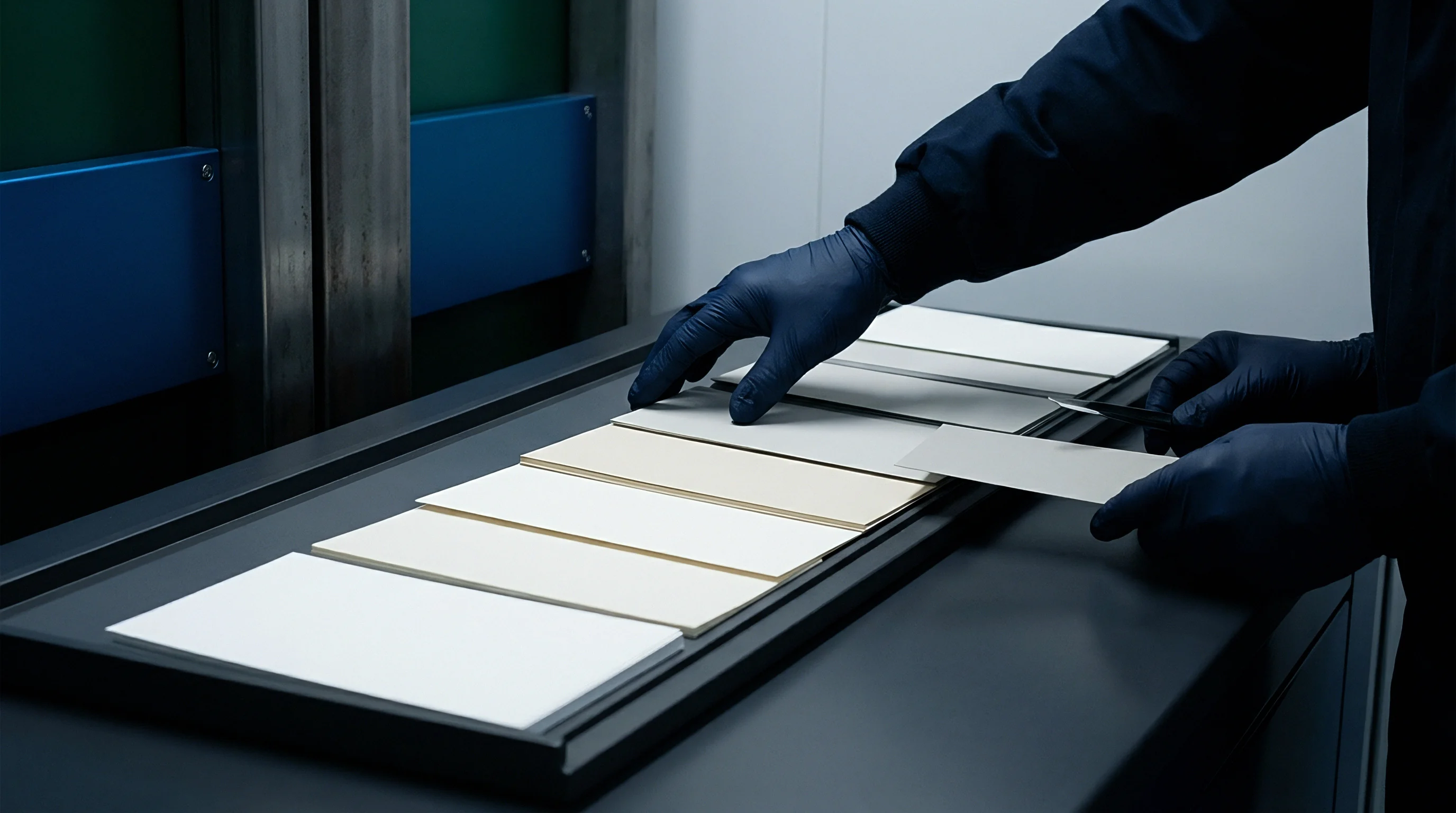
Evaluating scoreline quality requires quantifying bending moment reduction using specialized laboratory instruments. The L&W Crease Tester measures bending force at a 90-degree angle, comparing uncreased board stiffness against creased score resistance. A correctly sized matrix channel achieves a crease stiffness value between 30 percent and 50 percent of the uncreased sheet stiffness, ensuring reliable carton erection without side-wall bulging.
Cross-sectional analysis under magnification confirms internal ply separation profiles. Microscopic inspection verifies that the outer liner remains intact while internal layers separate into parallel, uniform micro-delamination zones.
| Test Parameter | Standard Target | Minimum Threshold | Maximum Threshold | Failure Indicator |
|---|---|---|---|---|
| Crease Bending Ratio | 40 percent | 30 percent | 55 percent | Carton panel bowing |
| Liner Elongation | 1.5 percent | 0.5 percent | 2.5 percent | Print surface cracking |
| Bead Height Uniformity | +/- 0.02 mm | +/- 0.04 mm | +/- 0.08 mm | Gluing alignment skew |
Quality checks performed at goods-in inspect incoming paperboard shipments for caliper variation across master reels. Caliper drift exceeding +/- 5 percent requires live adjustment of matrix channels on press to prevent localized scoring failures.
ISO 2471 opacity and ISO 536 grammage testing validate sheet uniformity prior to committing substrates to large converting runs. Standard procurement agreements enforce ISO 9001 quality compliance clauses, rejecting deliveries failing to meet specified stiffness limits.


Waste
Financial Impact of Incorrect Calculations
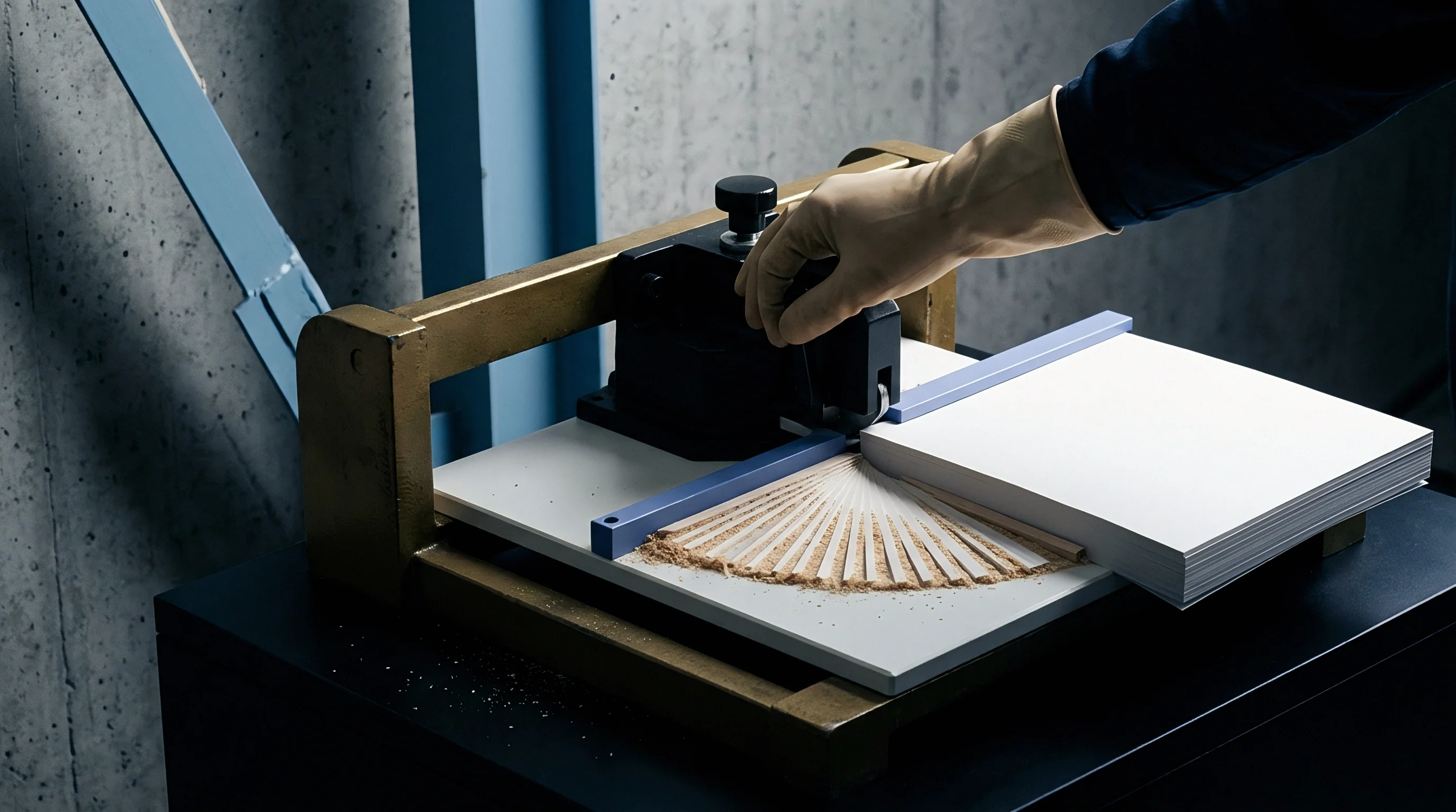
Selecting incorrect channel matrix dimensions triggers immediate line downtime and scrap generation during converting runs. An undersized matrix cuts through board plies, generating fiber dust that contaminates printing plates and gluing stations. Over-width matrix channels produce weak score lines, causing high-speed cartoning machines to jam during automated packaging operations.
Substrate waste rates escalate rapidly when press operators compensate for improper channel geometry by increasing overall platen pressure. Excess tonnage crushes the entire sheet surface, destroying structural carton strength and accelerating die-cutter mechanical wear. Correct calculation protocols align matrix selection directly with substrate physical properties, securing maximum converting speeds while preserving sheet structural integrity.
Improper channel calculations ruin finished packaging runs, resulting in full pallet rejections at client filling facilities.