Selecting Female Matrix Dimensions for Barrier Coated Folding Boxboard Converting
Barrier coated folding boxboard converting demands female matrix channels widened to one point seven times caliper to prevent micro-fissuring.


Geometry
Folding boxboard made with virgin mechanical core plies and chemical outer plies exhibits asymmetrical strain profiles during creasing. Coating the top surface with a functional polymer film or water-borne dispersion shifts the neutral axis of bending toward the barrier interface. Traditional creasing formulas built for uncoated board don’t account for how easily thin polymer membranes rupture.
Sizing the female matrix channel correctly keeps the coating from delaminating or developing micro-fissures along the outer bend radius.
Middle plies of mechanical pulp give the board bulk and bending stiffness while yielding under local compression. Outer chemical pulp plies handle tensile stress when cartons are erected and folded. Adding a barrier layer ~ such as a 15 to 30 gram per square metre polyethylene extrusion or a 6 to 12 gram per square metre aqueous dispersion ~ introduces a continuous non-fibrous skin.
Tightly bonded to the top pigment coat, this non-fibrous layer has a lower ultimate tensile strain limit than the bleached chemical pulp fibers beneath it.
Standard creasing channel width for folding boxboard scales directly with board thickness. The traditional equation W = 1.5 · t + dr defines channel width W, where t is board caliper and dr is creasing rule thickness. Using this baseline formula on barrier-coated board generates excessive surface tension along the crease bead shoulders, because the rigid barrier resists local ply movement and concentrates tensile strain over too narrow an area.
Strain Distribution Mechanics in Multi-Ply Furnish
Clean creasing relies primarily on delamination between internal mechanical pulp plies. As the creasing rule pushes top plies down into the female matrix channel, it creates two distinct shear zones inside the core. Mechanical fibers break apart under shear, letting the sheet bulge into the channel without cracking the top chemical pulp face.
A surface barrier layer stiffens the top face and alters how this internal shearing unfolds.
Greater bending resistance in the top ply delays internal shear when the rule makes contact. Peak tension builds on the coated surface because more penetration force accumulates before delamination starts inside the core. Widening the channel factor from 1.5 to 1.65 or 1.8 expands the internal shear zone.
This distributes surface strain across a broader arc, holding local stretch below the barrier film’s elongation-at-break threshold.
Dispersion barrier pinhole density remains under 0.05 defects per square metre when female channel width reaches 1.65 times board caliper under ISO 187 standard conditioning.
Changes in board thickness alter the required strain multiplier. Heavyweight boards above 450 micrometres in caliper require proportionally wider channels than lightweight 280 micrometre boards, since thicker mechanical cores store more strain energy before internal plies separate. The table below lists channel width multipliers across common barrier types and caliper ranges measured under ISO 534 testing standards.
| Barrier Coating Type | Coating Weight (g/m²) | Board Caliper Range (µm) | Rule Thickness (pt / mm) | Width Multiplier Formula |
|---|---|---|---|---|
| Aqueous Acrylic Dispersion | 6 – 10 | 250 – 380 | 2 pt / 0.71 mm | W = 1.60 · t + d_r |
| Aqueous Acrylic Dispersion | 8 – 14 | 385 – 550 | 2 pt / 0.71 mm | W = 1.68 · t + d_r |
| Low-Density Polyethylene (LDPE) | 15 – 25 | 280 – 420 | 2 pt / 0.71 mm | W = 1.65 · t + d_r |
| Low-Density Polyethylene (LDPE) | 20 – 30 | 425 – 600 | 3 pt / 1.05 mm | W = 1.75 · t + d_r |
| Polyethylene Terephthalate (PET) | 18 – 28 | 300 – 500 | 2 pt / 0.71 mm | W = 1.80 · t + d_r |
| Bio-Polymer (PLA / PHA) | 12 – 22 | 280 – 450 | 2 pt / 0.71 mm | W = 1.70 · t + d_r |

Barrier Film Behavior under Tensile Creasing Forces
Aqueous dispersion coatings react poorly to rapid strain rates on high-speed flatbed die-cutters running at 9,000 sheets per hour. Polymerized latex particles form film networks interspersed with inorganic fillers like talc or kaolin clay. Under fast rule impact, these dispersion films fracture brittly if surface strain exceeds two percent elongation.
Polymer extrusions like LDPE yield ductilely, stretching further before tearing, but can pull away from the double-coated top liner if side walls pinch too tightly.
Testing on 330 gram per square metre folding boxboard coated with 10 grams per square metre of dispersion barrier shows that channels sized at W = 1.5 · t + dr yield pinhole leakage in 14 percent of folded samples during dye penetration trials. Widening the channel to W = 1.68 · t + dr eliminates those defects without sacrificing crease definition, as the broader geometry lets the coated sheet form a rounded bead that relieves peak tension along the matrix shoulder.
Whether improved elasticity in modern bio-based polymer coatings will allow tighter female channels without compromising grease barrier performance across ninety-degree folds remains subject to ongoing mill trials.


Gap
Clearance between the female channel side wall and male creasing rule controls lateral shear during impact. Proper clearance folds board fibers smoothly into the channel without crushing the core. If side clearance is too tight, the board pinches against the matrix edge and shears the coating along the crease shoulder.
If it is too loose, fibers slip without establishing a clean delamination plane, creating wide, uneven creases that bulge during gluing.
Calculating side clearance follows directly from channel width. Single-side clearance Gs is half the difference between total channel width W and male rule thickness dr, expressed as Gs = (W – dr) / 2. Uncoated board uses a single-side clearance equal to 0.75 times caliper.
Barrier-coated grades require 0.80 to 0.90 times caliper to make room for the continuous film volume and prevent mechanical pinching.

Lateral Clearance Calculations for Creasing Rules
Dynamic registration errors on flatbed die-cutters throw off lateral clearance. Die board movement, counterplate expansion from ambient humidity changes, and sheet feed misalignments all push the male rule off-center. An offset of just 0.05 millimetres tightens clearance on one side while opening it up on the other.
Standard board tolerates this with minor crease asymmetry; barrier-coated board ruptures immediately on the pinched side.
Chamfering the female matrix edges gives an operational buffer against minor rule misalignment. Shoulders cut with a 30-degree to 45-degree chamfer engage the board surface gradually rather than striking with a hard shear edge. These smooth entrance angles spread vertical compression over a wider contact area, preserving barrier continuity through minor registration drift.
- Barrier Micro-Cracking occurs along the outer crease radius when narrow channels stretch surface fibers beyond their tensile limit.
- Bead Delamination develops when tight side clearances pinch the barrier film away from the top chemical face, leaving hollow air pockets beneath the coating.
- Delamination Flaking occurs when dispersion coatings with weak interfacial adhesion peel away in small flakes under heavy edge compression.
- Reverse-Side Rupture surfaces when deep rule penetration and excessive side clearance force mechanical core fibers straight through the unprinted back liner.
- Ridge Asymmetry comes from off-center rule alignment, creating unequal bend resistance and crooked folds on carton packaging lines.

Failure Modes from Compression Overlap
Creasing exerts vertical and horizontal forces at the same instant during die impact. Mechanical pulp in the core compresses to roughly half its original caliper under direct rule contact before expanding sideways into the female channel. If side clearance is restricted, compressed core fibers cannot shift into the shear zone.
Trapped in place, the core plies direct stress outward toward the barrier coating, tearing the surface membrane.
Fiber orientation strongly influences lateral displacement forces. Machine-direction fibers resist bending more than cross-direction fibers, exerting higher lateral pressure against matrix walls. Creasing parallel to the machine direction therefore requires slightly wider matrix clearance than cross-direction creases to balance surface strain.
Channels parallel to the machine direction need an extra 0.02 to 0.04 millimetres of width to avoid edge shearing.
Matrix selection guidelines prioritize expanding channel width over adjusting channel depth whenever micro-fissuring shows up along the outer crease shoulder.


Depth
Vertical clearance in the female matrix determines how deep mechanical pulp plies are driven into the channel. Channel depth D controls the reverse-side bead height. For uncoated board, standard practice sets matrix depth equal to uncompressed caliper t.
Barrier-coated grades require modest depth reductions to prevent over-stretching surface coatings during penetration.
As the rule pushes coated board into the matrix channel, bottom chemical plies form a bead inside the female groove. If matrix depth equals full sheet thickness, deep vertical movement pulls the top barrier coating into a sharp bend. Reducing channel depth by an offset Δ t limits penetration, yielding a broader, flatter crease bead that protects the film from peak tensile strain.

Rule Height Calibration against Board Compression
Selecting male creasing rule height depends directly on female channel depth and plate thickness. Standard cutting rules measure 23.80 millimetres (0.937 inches). Creasing rule height Hr is calculated by subtracting female matrix depth D and plate thickness from cutting rule height Hc, adjusted for board compression.
The formula Hr = Hc – D + Δ h sets baseline height, with Δ h accounting for controlled impression depth into the sheet.
Excessive rule height crushes board plies solid against the steel counterplate. This destroys internal bulk, preventing proper core delamination and leaving the board with high spring-back force when folded. Too little rule height leaves delamination incomplete, forcing the barrier film to absorb all bending stress.
The calculations below demonstrate depth selection for three common barrier-coated FBB calipers using 2-point creasing rules.
Take a 330 gram per square metre folding boxboard with a caliper of 500 micrometres (0.50 mm) and a 20 gram per square metre low-density polyethylene coating. Uncompressed caliper t is 0.50 mm. Standard FBB uses a channel depth D of 0.50 mm.
For this PE-coated variant, depth offset Δ t is set to 0.05 mm to protect the surface film, giving a matrix depth D of 0.45 mm. Combined with a width factor of 1.70 · t + dr, matrix width W equals (1.70 · 0.50) + 0.71 = 1.56 mm. Matrix dimensions of 1.56 mm · 0.45 mm establish optimal creasing conditions.
Consider a heavier 400 gram per square metre board with a caliper of 600 micrometres (0.60 mm) carrying a 10 gram per square metre dispersion barrier coating. Board stiffness is high and dispersion elasticity is low. Setting offset Δ t to 0.04 mm yields a matrix depth D of 0.56 mm.
Increasing the channel width multiplier to 1.75 accommodates the stiff mechanical plies, giving a matrix width W of (1.75 · 0.60) + 0.71 = 1.76 mm. Sizing the matrix at 1.76 mm · 0.56 mm prevents dispersion cracking while allowing full 180-degree folding.
Finally, consider a lightweight 260 gram per square metre board at 380 micrometres caliper (0.38 mm) coated with a 15 gram per square metre PET extrusion film. Rigid PET coatings resist bending and tend to tear along the crease center under deep rule penetration. Setting depth offset Δ t to 0.03 mm gives a matrix depth D of 0.35 mm.
With a width multiplier of 1.80, width W calculates to (1.80 · 0.38) + 0.71 = 1.39 mm, giving final matrix dimensions of 1.39 mm · 0.35 mm.
DIN 55437 acceptance standards require zero moisture vapor transmission degradation across a 180-degree crease line after twenty-four hours exposure.
Worked Dimensional Calculations for Poly Extruded Grades
Counterplate hardness influences effective channel depth during production runs. Pressboard counterplates compress slightly under continuous impression, gradually deepening over a 50,000-sheet run. Phenolic resin and steel counterplates maintain exact depth across long jobs.
CNC-milled steel counterplate channels offer total dimensional stability, holding depth within a plus or minus 0.005 millimetre tolerance across the entire die bed.
Platen deflection under tonnage introduces subtle vertical variations across large sheet formats. Center areas of the platen flex more than outer frame supports. Adjusting creasing rule heights across the die board with thin brass patching tape (0.005 to 0.015 mm thick) compensates for localized impression differences and keeps penetration consistent across all carton blanks.
Operating with an uncalibrated counterplate flattens dispersion barrier beads, risking batches of rejected folding carton stock that can write off forty-two thousand euros across multiple press runs.

Rupture
Polymer films and water-borne acrylic dispersions break down when local strain exceeds ultimate tensile elongation. Micro-fissures appear long before cracks become visible to the naked eye. Catching barrier defects early prevents costly scrap during liquid, frozen food, or dry grease-sensitive packaging runs.
Quality checks for barrier integrity rely primarily on chemical penetration tests and barrier rate measurements across folded creases. Penetration testing applies low-surface-tension dye solutions ~ such as red turpentine or water-glycol drops ~ directly to folded crease intersections. Sound barrier layers resist dye penetration for the required duration; damaged coatings let dye bleed into underlying paperboard fibers within seconds.
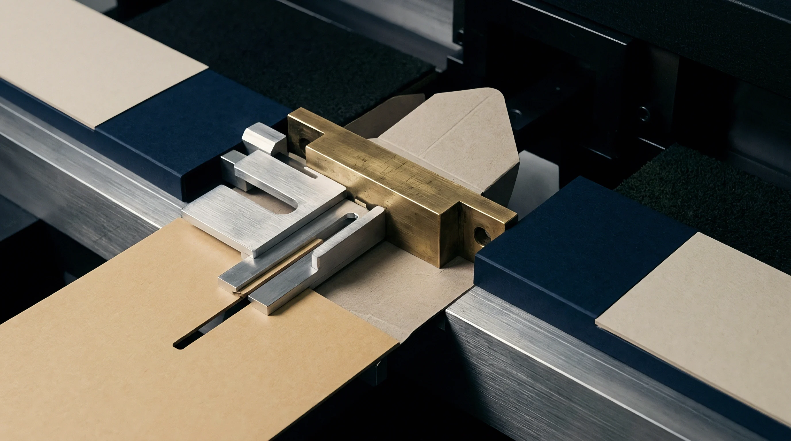
How Does Barrier Film Elasticity Shift Matrix Dimensions?
Elastic response in poly coatings buffers mechanical stress during rule insertion. Flexible polymers absorb local compression through elastomeric stretch, recovering original film thickness once pressure releases. Low-elasticity coatings ~ like high-density bio-polymers and mineral-filled aqueous dispersions ~ suffer plastic deformation or snap brittly under identical strain.
Polymers grow brittle as temperatures drop. Die-cutting barrier-coated board in unheated plants during winter raises rupture rates. Maintaining plant conditions at 23 degrees Celsius and 50 percent relative humidity per ISO 187 standards preserves film ductility and maximizes allowable crease deformation.
| Test Parameter | Standard Method | Uncreased Target Value | Max Allowable Crease Degradation | Primary Failure Cause |
|---|---|---|---|---|
| Water Vapor Transmission (WVTR) | ISO 15106-2 / ASTM F1249 | < 2.0 g/(m²·day) | +15% increase max | Micro-fissuring along bead shoulder |
| Water Absorption (Cobb 180 min) | ISO 535 / TAPPI T 441 | < 1.0 g/m² | < 3.0 g/m² post-fold | Barrier film delamination from ply |
| Grease Resistance (KIT Test) | TAPPI T 559 | KIT Level 12 | KIT Level 10 minimum | Pinhole formation at fold corners |
| Turpentine Penetration Resistance | TAPPI T 454 | > 1800 seconds | > 300 seconds post-fold | Brittle dispersion coat fracture |
| Cross-Crease Dye Penetration | Internal Standard / ASTM F1929 | Zero staining | Zero pinhole spots | Shear pinching from tight channel gap |
Testing Protocols for Post-Converting Barrier Defect Identification
Under optical magnification, converted blank failures fall into three distinct patterns. Line fractures show up as continuous parallel cracks along the outer fold axis, pointing to excessive surface tension from narrow channels. Edge flakes appear as localized coating detachment along shoulder contact lines, signaling heavy side-wall compression.
Corner pinholes occur at cross-crease intersections where rule tips create concentrated pinch points.
Quantifying post-converting barrier performance requires a structured evaluation during setup. Testing follows a clear workflow to catch subtle film defects before mass conversion begins.
- Sample ten carton blanks across all die positions immediately after initial make-ready.
- Fold all score lines to ninety and one hundred eighty degrees using automated lab equipment at production speed.
- Apply red dye penetration fluid along all folded score lines with a soft felt applicator.
- Leave dye fluid on folded score lines for exactly one hundred twenty seconds at room temperature.
- Wipe off excess surface dye using lint-free absorbent paper towels.
- Examine the reverse side of the board along score paths under ten-times magnification for dye bleed-through.
- Reject matrix dimensional setup if more than one pinhole spot appears across ten sampled blanks.
Barrier dispersion coatings require dedicated matrix channel adjustments rather than running on standard uncoated tooling configurations.


Audit
Goods-in inspection verifies caliper, moisture content, and coating thickness before press setup. Caliper variations over plus or minus three percent alter effective single-side creasing gaps. Moisture fluctuations shift fiber flexibility, changing internal delamination thresholds and required channel depths.
Verifying female matrix channels requires optical measurement tools or mechanical depth gauges. Self-adhesive plastic matrix strips attached to cutting plates can shift during long runs if press room temperatures rise above thirty degrees Celsius. Phenolic and steel counterplates eliminate adhesive creep, holding dimensional tolerances throughout million-impression contracts.
Make-Ready Verification on Press Counterplates
Press make-ready starts by verifying counterplate registration against male cutting and creasing rules. A carbon transfer sheet run under light impression shows exact rule contact across all channels. Uneven transfer highlights local height variations in the die board or inconsistent milling depth, requiring carbon patching adjustments before releasing the job.
Laser measurement systems mounted on die-cutting presses profile female channel dimensions in real time. Scanning laser heads measure channel width, depth, and edge chamfer profiles across milled counterplates before installation. Automated scanning eliminates operator caliper reading errors and generates digital audit dossiers for quality records.
- Phenolic Resin Counterplates offer high dimensional stability and wear resistance for long-run barrier packaging, resisting adhesive creep under press heat.
- Pressboard Channel Strips provide economical setup for short to medium packaging runs, requiring frequent checks to monitor channel wear over time.
- Milled Steel Counterplates deliver maximum precision for high-speed liquid packaging, maintaining exact channel dimensions indefinitely.
- Self-Adhesive Plastic Matrices enable rapid job changes on flatbed die-cutters, though they demand strict temperature control to prevent channel alignment drift.

Matrix Material Selection Decision Matrix
Selecting counterplate materials means balancing tooling cost against run length and defect risk. Liquid packaging for milk and juice demands zero defects, justifying expensive milled steel plates. Secondary dry food cartons with low-risk dispersion coatings run reliably on self-adhesive plastic or phenolic matrices.
Phenolic channel plates are standard for continuous runs exceeding fifty thousand impressions.
Matrix wall hardness dictates channel durability. Soft PVC matrix channels yield under heavy side-wall compression, widening by up to 0.08 millimetres after 20,000 impressions. This widening changes shear geometry, causing crease bead relaxation and crooked folding on packaging lines.
Crease bead symmetry under a magnifier reveals alignment errors long before barrier integrity tests report film leakage.
Standard purchasing specifications require supplied female matrices to maintain tolerances within plus or minus 0.015 millimetres across the entire plate for the full contract run length.

Tariff
Unit economics in folding carton production turn on converted yield per mill reel and scrap rates at the gluer. Choosing the wrong substrate generates hidden losses through press stoppages, barrier rejections, and eco-fee penalties at end-of-life. Matrix selection directly affects total landed carton cost through waste reduction and line speed optimization.
Press downtime from score line cracking costs between 250 and 400 euros per hour in lost capacity. Rejecting a single 100,000-carton lot wipes out material margin, wasting up to 15,000 euros in board, ink, and conversion energy. Investing in milled phenolic counterplates adds initial tooling outlay, but saves substantial scrap cost across high-speed runs.

Waste Arithmetic in High-Speed Packaging Lines
Comparing standard plastic matrix strips against precision milled phenolic counterplates illustrates the cost difference on a 200,000-carton run. A standard barrier-coated board (330 g/m² FBB, 0.50 mm caliper, 20 g/m² PE) running at 8,000 sheets per hour serves as the baseline model. The economic balance table below breaks down production expenses for each option.
| Cost Component | Self-Adhesive Plastic Matrix | Milled Phenolic Counterplate | Economic Variance |
|---|---|---|---|
| Initial Tooling / Plate Cost | € 180 | € 850 | + € 670 (Higher Tooling) |
| Make-Ready Alignment Time | 45 minutes (€ 187.50) | 15 minutes (€ 62.50) | – € 125.00 (Faster Setup) |
| Run Speed Cap (Impressions/hr) | 6,500 sheets/hr max | 8,500 sheets/hr max | + 30.7% Line Speed |
| Scrap Rate From Barrier Cracking | 2.8% (5,600 cartons) | 0.2% (400 cartons) | – 5,200 Cartons Saved |
| Substrate Scrap Value Lost | € 1,232.00 | € 88.00 | – € 1,144.00 Material Loss |
| Total Conversion Landed Cost | € 1,600.00 | € 1,000.50 | – € 599.50 Net Savings |
End-Of-Life Fee Structures and Recyclability Impact
Extended Producer Responsibility (EPR) regulations classify barrier packaging by repulpability and material stream purity. Monomaterial packaging with aqueous dispersion coatings qualifies for lower eco-fee tariffs than heavy polyethylene extrusions. Dispersion-coated board that repulps cleanly in standard mill hydrapulpers avoids the 150 to 300 euro per tonne landfill or incineration surcharge levied on non-recyclable composites.
Incorrect female matrix dimensions threaten recyclability ratings by pushing converters to increase coat weights. When converters bump dispersion coat weight from 8 g/m² to 16 g/m² to mask micro-fissuring from narrow matrix channels, excess latex reduces fiber yield during hydrapulping. High latex loads plug screening meshes, demoting recycled fiber batches to lower board grades and triggering higher producer responsibility fees.
Excessive creasing depth breaks barrier films while insufficient channel width crushes board plies into unrecoverable side cracks.
Optimizing matrix channel width to W = 1.68 · t + dr enables defect-free creasing at minimum functional coat weights. Keeping coat weights low preserves repulpability certification under CEPI laboratory protocols, cuts raw material spend, and maximizes fiber recovery yields at secondary paper mills.
Precision matrix dimensioning connects sheet physics, conversion throughput, and packaging sustainability compliance. Choosing the correct channel width and depth protects delicate functional coatings, maximizes line speeds, and delivers optimal unit economics per thousand converted cartons.