Paperboard Structural Creasing Mechanics and Matrix Clearance Sizing
Optimize matrix channel clearance using board caliper and rule thickness formulas to guarantee internal ply delamination while preventing outer liner score cracking.
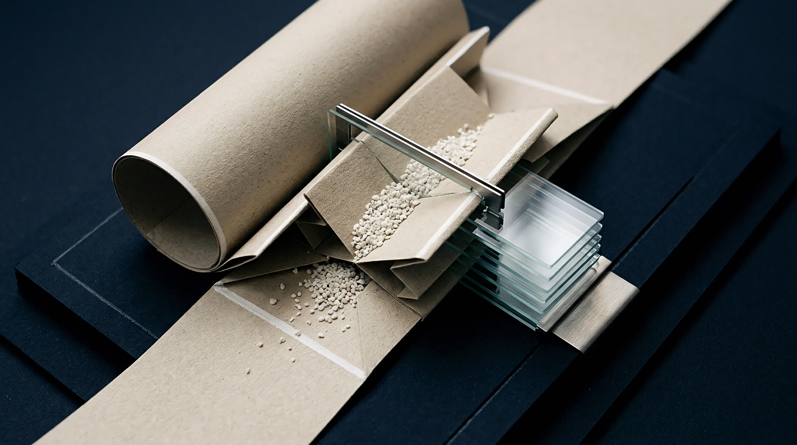
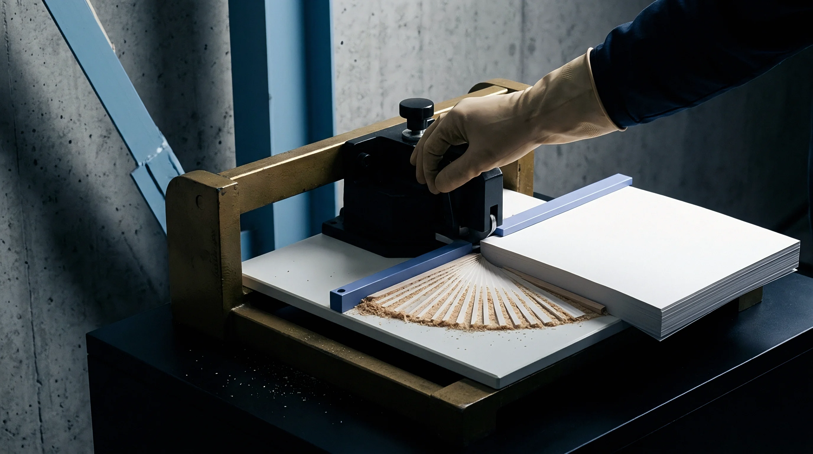
Deformation
When a steel rule forces paperboard into a grooved anvil, structural layers experience severe out-of-plane stress. Creasing is not meant to cut or crush the sheet flat; it breaks internal bonds between fiber plies to form a hinge while leaving the outer top liner and inner bottom liner intact. High-speed die-cutting equipment drives a round-edged steel rule into paperboard positioned over a counter-matrix channel.
As the rule descends, vertical compression combines with tension drawn across the channel shoulders. Double-shearing forces bend the board, shearing individual fiber layers apart along the central plane of its caliper.
Folding boxboard and solid bleached board rely on distinct fiber layers bonded at the wet end of the paper machine. Bleached hardwood kraft provides a smooth printing surface and high tensile strength on the top liner, while middle plies use mechanical pulp or recycled fiber for bulk and stiffness. Long-fiber softwood kraft forms the bottom liner to absorb tensile stretch.
During the stroke, transverse shear forces overcome internal bond strength (measured by TAPPI T 569 Z-directional tensile testing) and delaminate the middle plies. Once separated, these middle plies slide past one another like sheets of paper bent in an arc.
If internal delamination fails during die-cutting, subsequent folding places extreme tensile strain on the top liner. Unseparated middle plies force that outer layer past its elongation limit ~ typically three to four percent for coated bleached kraft board ~ cracking the surface coating and exposing raw fibers along the score line. When internal plies separate as intended, the central layers collapse downward into the matrix cavity to form a clean bead on the back of the board.
This delamination lets the sheet fold ninety or one hundred eighty degrees with minimal resistance, keeping the printed surface intact.
Dynamic compression behavior shifts with the board’s moisture content during converting. Under standard ISO 187 test conditions (twenty-three degrees Celsius and fifty percent relative humidity), equilibrium sheet moisture sits between six and eight percent. When mill storage or pressroom humidity drops below forty percent, the plies lose plasticizing moisture.
The hydrogen bonds between cellulose chains stiffen, raising Z-directional tensile strength while cutting cross-machine strain at break. That dry board resists internal shearing, so applying higher rule pressure simply fractures surface fibers instead of separating middle plies.
Grain direction directly affects creasing mechanics. Because fibers align mostly parallel to the machine direction during sheet formation, creases running parallel to the grain require less rule pressure to break internal bonds. Cross-machine creases force the rule across the fibers, generating higher initial resistance and requiring tight channel tolerances so the liner does not split.
Mapping internal deformation profiles under varying matrix clearances shows how ply shear displacement shifts across the sheet.
Proper creasing forms an internal sliding hinge within the middle plies rather than stretching the top liner to its breaking point.
Crease line failures usually stem from an improper deformation balance during the initial press stroke. The list below outlines common structural breakdowns observed on high-speed folding boxboard lines during carton blanking.
- Top Liner Cracking occurs when poor internal delamination leaves the outer layer under heavy tensile strain during folding, fracturing surface clay coatings and exposing raw fibers along the crease spine.
- Bottom Liner Bursting occurs when deep rule penetration or an overly narrow matrix channel punctures the interior surface of the blank during the press stroke.
- Asymmetric Bead Formation results from slight register misalignment between the creasing rule and matrix channel, forcing uneven shear that creates crooked folds on automatic cartoning lines.
- Crease Stiffness Retention happens when shallow rule penetration fails to break middle-ply bonds, leaving high residual folding torque that bows carton side panels after gluing.
Crease depth governs folding torque, though over-creasing simply fractures outer fibers. A score line holds up only if clean internal delamination happens before the sheet encounters downstream folding forces. When creasing rule geometry matches board caliper, the score creates a flexible hinge while keeping adjacent carton panels stiff.
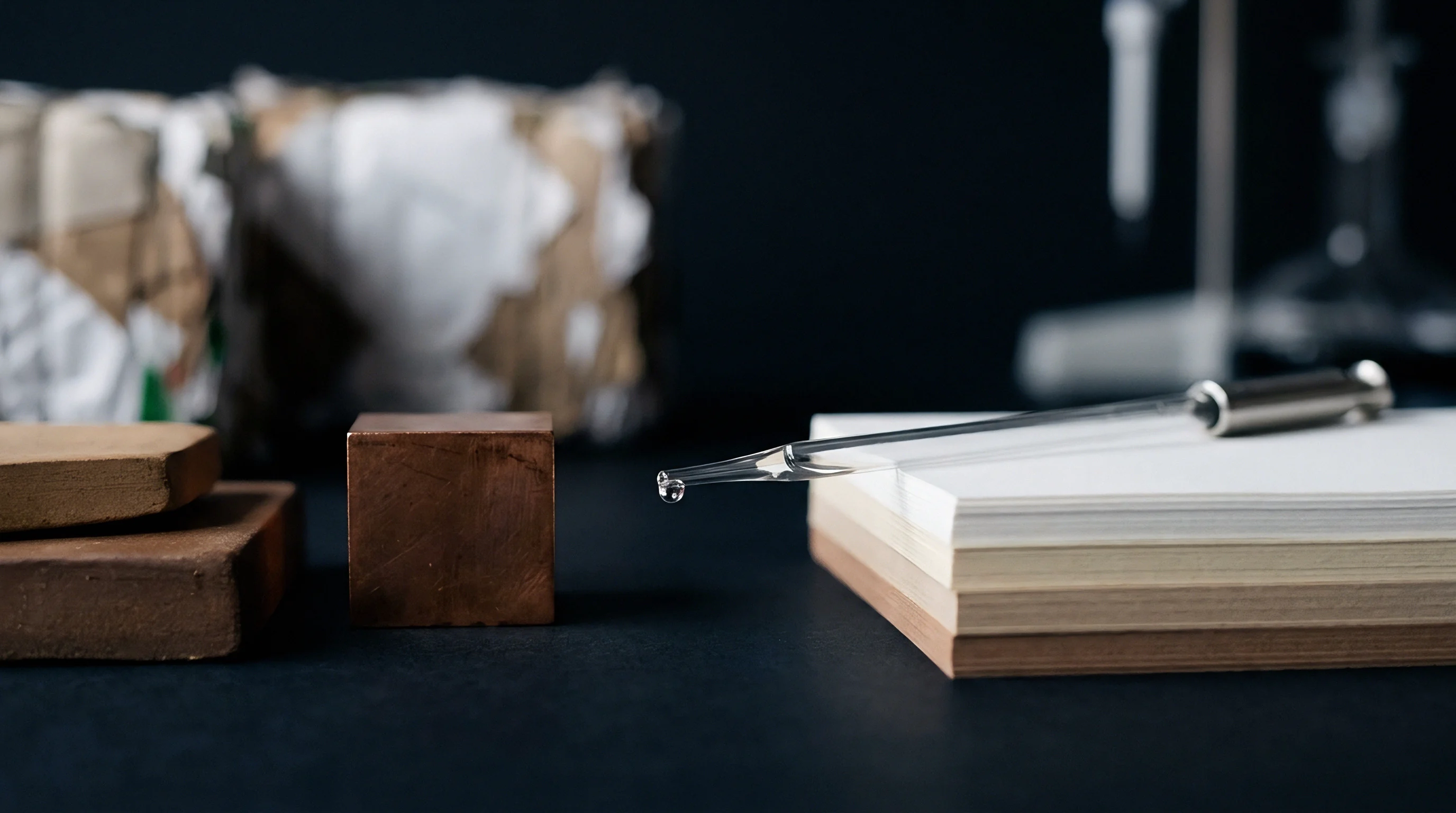
Channel
The geometry of the female die groove dictates whether a score line functions as a flexible hinge or fractures cleanly under stress. The counter-matrix channel provides the open volume that receives paperboard displaced by the creasing rule. Sizing it properly means balancing board caliper, creasing rule thickness, and channel depth.
Channel width sets the distance between shearing edges, while channel depth determines how far the rule can push the reverse bead before it bottoms out against the counter substrate.
Calculating matrix channel width relies on empirical formulas tailored to the substrate. For solid bleached sulfate and folding boxboard, standard matrix width equals one point five times the rule thickness plus one point four times board caliper ~ written mathematically as channel width W equals one point five times rule thickness t_r plus one point four times board thickness t_b. For less elastic stock like coated recycled board or unbleached kraft, the caliper multiplier rises to one point five or one point six to account for denser fiber structures and reduced compressibility.
Channel depth depends directly on board caliper. For standard folding boxboard up to four hundred microns, matrix channel depth D should equal board thickness t_b. Above five hundred microns, depth is usually set between eighty-five and ninety percent of caliper to maintain solid compression against the bottom liner.
If the channel is too shallow, the rule cannot fully form the reverse bead, leaving middle plies intact and increasing folding torque. If it is too deep, the board stretches into the groove without receiving enough compression to break internal bonds.
| Board Caliper (pt) | Board Caliper (mm) | Rule Thickness (pt) | Rule Thickness (mm) | Matrix Depth (mm) | Matrix Width (mm) |
|---|---|---|---|---|---|
| 12 pt | 0.30 mm | 2 pt | 0.71 mm | 0.30 mm | 1.49 mm |
| 16 pt | 0.40 mm | 2 pt | 0.71 mm | 0.40 mm | 1.63 mm |
| 20 pt | 0.50 mm | 2 pt | 0.71 mm | 0.50 mm | 1.77 mm |
| 24 pt | 0.60 mm | 3 pt | 1.05 mm | 0.60 mm | 2.41 mm |
| 28 pt | 0.70 mm | 3 pt | 1.05 mm | 0.70 mm | 2.55 mm |
| Calculations based on formula: Width = 1.5 Rule + 1.4 Caliper for solid bleached sulfate board under ISO 187 conditioning. | |||||
Matrix clearance directly drives the crease stiffness ratio ~ defined in ISO 5628 as the bending resistance along the crease divided by the bending resistance of uncreased board. High-speed automated cartoning lines usually target crease stiffness ratios between thirty and fifty percent. Ratios above sixty percent point to incomplete shear separation, which causes jams during carton erection, while values under twenty percent signal damaged fibers that weaken box stack strength.
A matrix depth setting of 0.40 mm paired with a 1.63 mm channel width on 16 pt board yields a crease stiffness ratio of 38 percent under ISO 5628 test parameters.
Establishing proper matrix channel dimensions requires a few precise steps before setting up production tooling for a converting job.
- Measure paperboard caliper using a digital micrometer under a dead-weight load of fifty kilopascals per ISO 534 to determine true board thickness.
- Select creasing rule thickness based on board caliper: two-point rule for calipers up to five hundred microns, and three-point rule for heavier board.
- Calculate theoretical channel width using the standard empirical multiplier for the board grade.
- Choose a commercial counter-matrix strip matching the calculated depth and closest standard width.
- Mount test channels on press, run sample sheets, and inspect cross-sections under a microscope to evaluate ply delamination.
Channel width variations immediately show up in fold quality. Narrow channels pinch the paperboard, driving the creasing rule into the surface liner and rupturing fibers along the outer score edges. Oversized channels let shear forces dissipate across too wide an area; the board sags into the groove without building the Z-directional stress needed to separate internal plies, leaving rounded, inconsistent corners.
Tooling purchasing specifications typically require channel widths within plus or minus zero point zero five millimeters of target to ensure reliable performance on automatic packaging lines.


Press
Converting presses deliver high dynamic impact forces at speeds over ten thousand sheets per hour. Energy transfer across the sheet depends entirely on the mechanical interface between platen die, rule, and counterplate. Platen deflection, rule height calibration, and matrix material selection determine how stable crease quality remains over long production runs.
Much of the make-ready effort goes into leveling the impression plate so crease depth stays uniform without crushing the sheet.
Choosing counter-matrix materials comes down to balancing make-ready setup time, dimensional stability, and wear resistance. Self-adhesive strips made of pressboard or vulcanized fiber stick directly onto steel counterplates quickly, making them practical for short to medium runs. Long-run operations rely instead on solid phenolic resin plates or micro-milled steel counterplates.
Phenolic counters resist heat and hold exact groove geometry through millions of impressions, preventing channel wall collapse under heavy shear loads.
What Matrix Thickness Best Prevents Liner Delamination?
Determining counter-matrix thickness requires balancing board caliper against steel rule height. Standard cutting rules measure twenty-three point eighty millimeters in height. Creasing rules sit lower than cutting rules by an amount equal to the board caliper plus the matrix base thickness.
If the creasing rule is too high, the press stroke crushes paperboard at the base of the score line and bursts the bottom liner. If it sits too low, crease formation relies almost entirely on matrix depth, lowering ply shear efficiency. Press speed depends on the viscoelastic recovery rate of the bottom liner.
| Matrix Material | Shore D Hardness | Maximum Impress Life | Channel Width Drift (100k sheets) | Thermal Stability Index |
|---|---|---|---|---|
| Pressboard Strips | 75 D | 50,000 sheets | +0.12 mm | Moderate |
| Pultruded Fiber Strip | 85 D | 250,000 sheets | +0.05 mm | High |
| Milled Phenolic Plate | 92 D | 1,000,000 sheets | +0.02 mm | Very High |
| Milled Steel Plate | 100 D | 5,000,000+ sheets | 0.00 mm | Excellent |
Pressroom environment affects tooling calibration over long shifts. Shifts in temperature and humidity alter board dimensions and mechanical behavior. High humidity softens fibers and increases compressibility; under these conditions, standard creasing rule heights may not generate enough shear force, requiring tighter channels or higher pressure.
Dry air hardens the board, raising the risk of liner cracking unless rules are relieved or wider matrix channels are installed. Matrix channels frequently compact during extended production runs.
Standard tooling specifications mandate that creasing rule height must sit lower than cutting rule height by exactly the board caliper plus the counterplate base thickness.
Make-ready technicians follow specific operational checks when setting up high-speed die-cutting equipment. The list below governs matrix setup before starting a production run.
- Substrate Hardness Calibration matches counterplate material density to run length so channel walls withstand repeated impact without spreading.
- Impression Leveling Verification uses carbon impression paper to map platen pressure across the cutting die surface.
- Channel Alignment Checks verify that creasing rules center inside matrix channels within zero point zero three millimeters.
- Rule Height Adjustment compensates for localized caliper variations across different mill roll batches.
Crease cracking is frequently attributed to mill batch inconsistencies ~ such as shifts in coating elasticity or internal bonding ~ rather than channel wear or misaligned rules. While fiber variability occurs, worn matrix channels, channel wall degradation, or debris buildup in the groove remain the primary mechanical causes of folding defects on high-speed lines.

Coating
Applied surface finishes significantly change how the top liner behaves during folding. Converters use polyethylene extrusion laminates, biaxially oriented polypropylene films, dispersion barrier coatings, and heavy UV lacquers to add gloss or block water and grease. These layers create composite structures.
As the paperboard flexes along a crease, the coating has to stretch with the top liner without cracking or peeling away from the fiber substrate.
Polymer films and liquid coatings have vastly different elongation limits than underlying board fibers. High-density polyethylene laminates can stretch past two hundred percent at break, allowing them to flex smoothly over creases without rupturing. High-solids UV radical varnishes and soft-touch matte coatings, by contrast, fail at elongation limits under two percent.
When applied to coated folding boxboard, these brittle finishes crack along the score line even when internal fiber plies delaminate cleanly.
| Surface Finishing Type | Application Weight (g/m²) | Elongation at Break (%) | Crease Cracking Risk | Recyclability Impact |
|---|---|---|---|---|
| Water-Based Dispersion Varnish | 4 to 6 g/m² | 5% to 8% | Low | None (Fully Recyclable) |
| Radical UV Gloss Lacquer | 6 to 10 g/m² | 1.5% to 2.5% | High | Minimal |
| BOPP Gloss Lamination Film | 12 to 15 g/m² | 120% to 150% | Very Low | High EPR Penalty |
| PET Metallized Film Laminate | 18 to 24 g/m² | 60% to 80% | Moderate | Recycling Rejection |
| Dispersed Polymer Barrier Coating | 8 to 12 g/m² | 12% to 18% | Low to Moderate | Passes EN 13430 |
Coating adhesion directly affects crease performance. When surface energy mismatches produce weak bonding between clay coatings and plastic films, bending stress causes localized separation at the interface. This micro-delamination shows up as flaking or blistering along the outer fold.
Corona treating plastic films above forty-two dynes per centimeter helps prevent interfacial separation during creasing.
Surface coatings with elongation limits under two percent fracture along creased folds regardless of internal fiber ply delamination efficiency.
Specifying board finishes requires full documentation of mechanical material properties. The checklist below defines parameters required on packaging job dockets to avoid crease failure.
- Coating Elongation Rating documents maximum tensile strain limits of inks and lacquers to ensure compatibility with score line bend radii.
- Interfacial Bond Strength measures cross-hatch tape adhesion per ASTM D3359 on finished coated sheets prior to die-cutting.
- Barrier Layer Flexibility verifies that grease or water vapor barriers stay continuous without micro-fracturing across ninety-degree folds.
- Recyclability Compliance Certificate confirms that surface films or coatings meet scheme guidelines like EN 13430 or CEPI recyclability standards.
Barrier-coated boxboard presents unresolved issues with long-term moisture retention along creased edges. Creasing can form microscopic cracks within thin inorganic or polymer barrier layers without showing any surface defects. These micro-cracks degrade water vapor transmission rates and mineral oil barriers along package folds, leading to potential compliance failures during shelf-life testing of dry food packaging.
Cost
Improperly sized matrix channels carry immediate financial penalties in both converting and packaging operations. Weak or inconsistent creases lead to misfeeds, jams, and bowed panels on high-speed folder-gluers. Modern gluing lines operating at four hundred meters per minute require exact crease stiffness to fold cartons reliably.
Excessive folding torque bows side panels outward, prompting automatic packing machines to reject blanks during high-speed filling.
Spoilage caused by faulty creases extends well past the converting plant onto client packing lines. Score cracking on high-speed gluing lines drives up waste costs substantially. If a pharmaceutical boxboard run shows edge cracking across three percent of cartons, the customer rejects the entire pallet batch over visual defects and unreadable serialization barcodes.
Re-running a fifty-thousand-carton order means buying replacement board, spending extra die-cutting time, re-varnishing, and paying expedited freight. Spending more upfront on phenolic matrix plates pays back quickly by eliminating waste on long runs.
Sustainability schemes add direct regulatory costs to finished packaging. Under European Extended Producer Responsibility guidelines and local waste laws, film-laminated paperboard faces higher fees based on recyclability grades. Full-surface plastic film laminations carry steeper end-of-life processing surcharges than recyclable dispersion coatings.
If film lamination is added just to hide surface cracking on poorly creased board, the brand owner pays a penalty on every unit sold.
Take a converting run of two million folding cartons made from sixteen-point boxboard. Option A uses standard pressboard matrix strips with low-cost UV varnish, tolerating a two percent cracking spoilage rate and requiring three press stops per shift to swap worn strips. Option B pairs precision-milled phenolic counterplates with a flexible water-based dispersion coating, eliminating matrix wear and reducing cracking spoilage to zero point zero five percent.
Option B adds twelve hundred dollars in upfront tooling for the phenolic plate, but saves four thousand eight hundred dollars in wasted board and six press make-ready hours over the run.
Calculating landed unit cost requires factoring in make-ready waste, press speeds, spoilage, and regulatory fees. The equation below defines total cost per thousand units:
Total Unit Cost = ( Material Cost + Tooling Amortization + Press Run Cost + Spoilage Loss + EPR Fees ) / Delivered Volume
A buyer rejected a forty-thousand-unit shipment of cosmetic packaging after minor channel clearance errors caused subtle varnish flaking along main display panel crease lines.