Non-Contact Caliper Measurement Systems on High Speed Packaging Board Lines
Non-contact optical gauges eliminate mechanical board compression on high-speed lines, enabling tighter cross-machine caliper targets and reduced fiber mass.
Beam

Laser Triangulation and Confocal Chromatic Physics
Measuring optical thickness on high-speed paperboard webs relies on displacement sensors installed in opposing pairs across the sheet pass line. Dual laser triangulation heads project focused semiconductor diode beams onto the upper clay coating and bottom unbleached kraft back. Photodetector arrays then pick up the reflected spatial peaks to calculate distance to each surface relative to a fixed mechanical reference plane.
At line speeds above 600 meters per minute, severe vertical web movement forces sensor heads to cover wider measurement gaps without losing sub-micron resolution. Standard triangulation heads use 405-nanometer blue diode emitters to restrict light penetration into translucent cellulose fibers and bleached kaolin coating layers. Longer red wavelengths sink deeper into porous top plies, creating false distance readings that artificially inflate apparent board thickness.
Thermal drift can throw off optical geometry. Ambient temperature swings in the machine room alter the physical gap between top and bottom sensors mounted on solid steel frames. Confocal chromatic displacement sensors bypass optical scattering issues by exploiting chromatic aberration inside dedicated lens sets.
White light from an LED emitter passes through refractive optics that split wavelengths along the vertical measuring axis, focusing each spectral component at a distinct distance from the optical housing. Reflected light travels back through a pinhole aperture to a spectrometer, which reads the peak wavelength to pinpoint the location of the packaging board surface.
Surface texture directly influences optical signal integrity. Multi-ply folding boxboard has local surface unevenness from fiber orientation, calender nip marks, and micro-embossing. Because confocal chromatic systems collect reflected light across a larger numerical aperture than narrow laser spots, they average out localized micro-roughness before sending coordinate values to the profiling computer.
This optical filtering smooths raw distance readings on heavily coated solid bleached sulfate sheets at full line speed.
Electromagnetic Air-Gauge Hybrids and Terahertz Profiling
Air-gauge eddy current hybrids combine optical position sensing with electromagnetic proximity detection. An upper optical head tracks the top board surface, while a lower inductive eddy current probe follows a metal reference shoe or continuous ground plate beneath the moving web. Pneumatic air bearings establish a constant cushion between the board back and shoe, holding a fixed 50 to 100 micrometers pneumatic gap.
The inductive sensor registers impedance shifts in the ground plate caused by spatial movement, creating an absolute baseline that cancels out web flutter artifacts. These hybrid layouts hold up well against dust from loose clay coatings and virgin softwood starch debris on heavy packaging lines.
Terahertz time-domain spectroscopy gauges substrate thickness by sending pulsed electromagnetic waves straight through the board. A transmitter sends picosecond pulses through the moving web to an opposing receiver. Moisture, cellulose fibers, and mineral pigments alter both wave velocity and phase amplitude.
By tracking absolute time of flight and phase delay, the receiver calculates total thickness and internal density distribution. Because pulses travel straight through the sheet, terahertz systems remain unaffected by web flutter.
Relative humidity fluctuations between 45 percent and 65 percent at 23 degrees Celsius alter board moisture content sufficiently to adjust non-contact optical thickness calculations by up to 1.8 micrometers on 350 gram per square meter folding boxboard.
Mechanical Vibration and Optical Scattering Failure Modes
Web flutter distorts optical reflections. High line speeds generate aerodynamic lift, ripples, and twist between guide rolls. Once local sheet inclination exceeds three degrees relative to the sensor axis, specular reflection misses the receiver array, causing sharp signal drops.
Internal signal processors must then freeze the last valid value or interpolate false numbers, generating artificial thickness spikes in cross-machine profile maps.
Dust buildup quickly clouds optical windows. Coated board lines produce airborne calcium carbonate, titanium dioxide, and loose synthetic binder particles that settle on emission lenses, scattering laser paths and weakening return signals. Automated air knives clear the glass surfaces continuously with dry, oil-free compressed air at 0.3 megapascal to maintain clean optical paths.
| Sensing Technology | Measurement Principle | Sampling Rate | Caliper Precision | Primary Disturbance Mechanism |
|---|---|---|---|---|
| Dual Laser Triangulation | Opposing optical distance triangulation | 100 kHz | plus minus 0.5 microns | Web flutter and coating penetration |
| Confocal Chromatic | Wavelength-encoded spectral distance | 70 kHz | plus minus 0.2 microns | Optical window dust buildup |
| Air-Gauge Eddy Current Hybrid | Inductive proximity with pneumatic air shoe | 20 kHz | plus minus 0.4 microns | Pneumatic supply pressure drift |
| Terahertz Time-Domain | Electromagnetic pulse time of flight | 10 kHz | plus minus 0.8 microns | Substrate moisture gradient shifts |
On a high-speed machine floor, physical environmental isolation determines baseline optical gauge reliability. Temperature swings across the frame distort alignment tolerances between upper and lower sensors. Baseline drift typically stems from frame thermal growth rather than diode aging or optical component degradation.
- Optical beam path occlusion occurs when loose coating flakes or severed edge slitting fibers block the semiconductor diode light path, triggering immediate profile baseline dropouts across specific cross-machine zones.
- Specular scattering attenuation manifests on high-gloss coated SBS packaging board when smooth surfaces reflect light away from the collecting photodetector array at acute web angles.
- Thermal C-frame deformation arises when ambient machine hall temperature swings alter the geometric distance between upper and lower displacement heads, introducing steady baseline offset errors.
- Aerodynamic boundary layer lifting forces lightweight board grades out of the optimal optical focal zone, creating localized thickness errors that misrepresent true web caliper.

Transit
Aerodynamic Boundary Layers and Web Flutter Dynamics
Continuous paperboard webs running at production speeds drag boundary air layers along both surfaces. As line speeds climb from 300 to 800 meters per minute, these viscous air layers thicken, creating localized pressure pockets against stationary guide frames. The resulting pressure differences drive vertical oscillations across the sheet.
At higher speeds, vertical travel exceeding 1.5 millimeters pulls the web outside the linear range of standard displacement heads, degrading profile accuracy.
Substrate stiffness helps limit this aerodynamic lift. Heavy containerboard and thick multi-ply coated grades have enough machine-direction bending stiffness to damp out micro-vibrations across short open draws. In contrast, lightweight boxboard flexes easily in turbulent air, setting up standing waves between stabilizer rolls.
Air-foil stabilizer plates placed ahead of the measurement frame strip away boundary layer air so the sheet passes flat through the optical gap.

Moisture Gradients and Thermal Expansion Phase Shifts
Water content directly dictates board caliper. As the web passes through steam showers, re-moisturizing units, and multi-cylinder dryer sections, internal moisture distributions shift constantly. Moisture absorption swells fiber walls in the z-direction, expanding total sheet thickness before the structure reaches mechanical equilibrium.
Sensors mounted right after dry-end calender stacks read hot, dry board that will shrink horizontally and expand vertically as moisture evens out through the sheet thickness.
Thermal contraction happens quickly through cooling loops. A board web leaving the final gloss calender at 85 degrees Celsius shrinks in all dimensions as it cools to ambient reel hall temperatures around 25 degrees Celsius. Non-contact measurement routines apply temperature compensation curves based on the thermal expansion coefficient of each furnish.
Neglecting web temperature at the scanner frame leads to systematic overestimation of final cooled caliper.
High speed board webs transport boundary air layers that require active mechanical vacuum stabilization to prevent optical distance sensor saturation.
Protocol for Thermal and Vibration Zero Point Alignment
Maintaining measurement accuracy across continuous production runs requires systematic optical zeroing. The following sequence carries out automated zeroing without breaking or stopping the sheet.
- Retract the non-contact sensor C-frame fully into the off-sheet operator side maintenance garage.
- Purge all optical windows using high-pressure dry air blasts to dislodge accumulated fiber debris and coating dust.
- Position an automated certified internal reference gauge block into the optical path gap.
- Capture zero-point optical intensity and spatial baseline measurements across fifty discrete internal sample cycles.
- Calculate thermal compensation factors based on current C-frame integrated RTD temperature sensor readings.
- Verify proximity sensor output against mechanical reference standards prior to re-entering the active sheet web.
Sensor heads re-enter the live web after completing calibration protocols, tracking edge boundaries automatically. Surface topography alters laser beam scattering when moisture content drops below four percent. Thin lightweight board grades moving at elevated line speeds mandate wider optical sensor gaps to compensate for aerodynamic uplift forces.
Array

Traversing C-Frames versus Fixed Multi-Point Arrays
Traversing C-frames move a single pair of opposed sensors across the sheet width at speeds between 100 and 300 millimeters per second. On a machine running at 600 meters per minute, one pass across a 4.5-meter web takes 15 seconds, during which 150 meters of board moves downstream. The sensor traces a diagonal path along the roll, blending cross-machine caliper variations with machine-direction grammage shifts.
While traversing frames keep capital costs down, they miss narrow, high-frequency streaks that slip between scan passes.
Fixed multi-point arrays mount stationary optical or electromagnetic sensors across the entire machine width. Spacing usually matches automated calender zones at 30 to 50 millimeters. These arrays record cross-machine caliper continuously at sampling rates up to 100 kilohertz, cleanly separating cross-machine structure from machine-direction speed variations.
High hardware costs and multi-channel calibration upkeep remain the main obstacles to installing fixed arrays.

What Signal Filtering Prevents Edge Roll off Artifacts?
Sheet edges present severe physical irregularity. Machine-direction deckle straps, air-trim squirts, and slitting knives leave edge tapering and loose fiber burrs within fifty millimeters of the margin. As optical sensors cross the web edge, sudden light refraction drops and partial beam cutoffs create steep false readings known as edge roll-off artifacts.
Left unfiltered, these bad data points distort automated profile averages and drive unwarranted calender adjustments along the sheet edges.
Digital filtering removes these false edge readings. Infrared edge detectors track the physical margins in real time, allowing finite impulse response filters to mask raw readings within a dead-zone of 15 to 35 millimeters from the edge. Spatial moving averages then smooth the remaining data, feeding clean cross-machine profiles to the line automation system.
- Scan velocity optimization balances cross-machine profile resolution against mechanical wear on traversing frame drive belts and linear bearing rails.
- Spatial zone mapping aligns internal non-contact measurement channels with downstream slitter knife locations to ensure every finished roll core possesses precise average caliper records.
- Edge dead-zone configuration prevents false optical trim signals from warping automated soft-nip calender profile adjustments.
- High-frequency noise suppression strips out localized surface coating grain variations without dampening macro-level web thickness trends.

Cross-Machine Spatial Resolution and Filtering Criteria
Spatial resolution determines the narrowest caliper defect a system can catch. Traversing heads tend to blur narrow ridges because laser spot sizes and integration windows average data over a finite width. For instance, a 1.0 millimeter laser spot with a 10-millisecond integration time moving at 200 millimeters per second gives an effective resolution of about 3.0 millimeters along the scan trace.
Narrow ridges from localized calender roll wear or damaged doctor blades frequently pass through low-resolution filters undetected.
Signal processing pipelines use recursive Butterworth low-pass filters to remove mechanical vibration noise from raw profiles. Cutoff frequencies are matched to the width of the calender zone actuators. Filtering raw spatial profiles below the roll’s physical response width causes loop hunting, as actuators try to chase narrow thickness spikes that soft-nip rolls are physically incapable of correcting.
Technical supply agreements executed under ISO 186 sampling procedures require mill quality systems to exclude the outer fifty millimeters of the web edge from contractual thickness compliance profiles.

Discrepancy
Contact Micrometer Pressure versus Optical Surface Detection
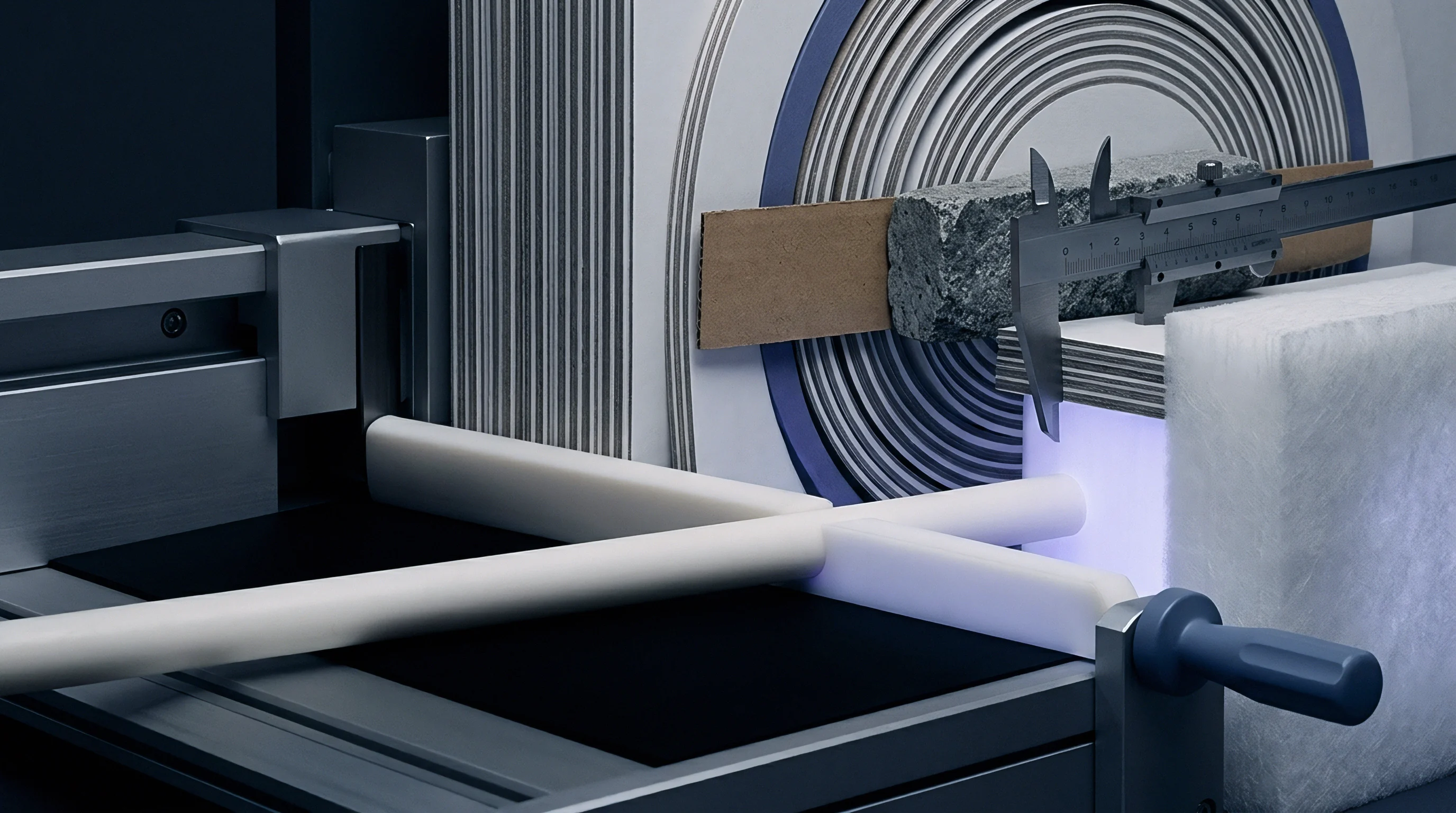
Standard laboratory testing uses contact micrometers governed by ISO 534 and TAPPI T 411. These methods apply a static dead-weight pressure of 100 kilopascals plus minus 10 kilopascals through a circular foot measuring 200 square millimeters. Paperboard compresses viscoelastically under load: bulky mechanical pulp cores, soft virgin fiber plies, and uncompacted recycled furnishes yield noticeably between metal anvils.
The resulting contact caliper reflects a compressed state rather than the true uncompressed volume of the sheet.
Non-contact optical gauges capture surface boundaries in their uncompressed state, registering the peaks of exposed fibers and clay coatings without exerting downward force. As a result, non-contact optical caliper runs higher than off-line contact micrometer readings on the same board sample. This difference widens on high-bulk, low-density folding boxboard containing mechanical pulp centers.
| Board Substrate Grade | Nominal Grammage (g/m²) | ISO 534 Contact Caliper (µm) | Non-Contact Optical Caliper (µm) | Caliper Offset Delta (µm) | Substrate Compression Factor (%) |
|---|---|---|---|---|---|
| Solid Bleached Sulfate (SBS) | 250 | 310.2 | 314.8 | plus 4.6 | 1.46 |
| Folding Boxboard (FBB) – Mechanical Core | 300 | 460.5 | 469.1 | plus 8.6 | 1.83 |
| Coated Recycled Board (CRB) | 350 | 485.0 | 492.3 | plus 7.3 | 1.48 |
| Uncoated Kraft Linerboard | 175 | 242.1 | 248.4 | plus 6.3 | 2.54 |
Substrate Surface Roughness and Coating Pore Offsets
Surface micro-topography creates a persistent offset between optical reflection planes and mechanical contact planes. Uncoated kraft board consists of an open mesh of cellulose fibers with peak-to-valley heights often exceeding 15 micrometers. When a flat micrometer foot lands on the sheet, it bridges the highest fibers and compresses them.
A single-spot laser sensor, by contrast, dips into intermediate valleys depending on spot diameter and beam angle, yielding an average height that sits below the plane touched by a flat anvil.
Coated board behaves differently. Pigmented clay coatings fill surface valleys, creating a smooth plane with micro-porosity below 1.0 micrometer. Light from laser triangulation heads reflects largely off the outer pigment surface, but partial transmission into semi-translucent binders and titanium dioxide particles causes sub-surface scattering.
This delay in photon return artificially depresses the calculated surface position by 1.0 to 3.0 micrometers unless corrected by grade-specific color offsets.
Contractual packaging specifications referencing ISO 534 mechanical micrometer protocols force mills to apply automated mathematical offsets to off-line lab test figures before comparing values against in-line optical sensor profiles.
Calibrating Non-Contact Values to Certified Off-Line Baselines
Reconciling on-machine optical profiles with certified laboratory release tests requires empirical calibration models. Linear regressions map raw optical data against contact micrometer readings taken from reel strips. Operators cut full-width samples from parent rolls and condition them at 23 degrees Celsius and 50 percent relative humidity per ISO 187.
An automated laboratory bench then measures thickness at 10-millimeter intervals across the exact path tracked by the on-line scanner prior to winding.
Calibration software calculates slope and intercept corrections for each furnish and board grade, subtracting roughness peaks and viscoelastic compression deltas from the raw optical signal. This generates a synthetic contact-equivalent thickness profile on operator displays, allowing quality auditors and machine crews to track compliance against legacy mechanical standards without interrupting production.
Determining how future non-contact acoustic sensors will resolve localized density variations inside heavily loaded recycled fiber cores without relying on empirical off-line compression factors remains an open technical challenge for mill metrology.

Sentry
Closed-Loop Control Integration with Soft-Nip Calenders
On-line non-contact caliper sensors provide the primary feedback for automated cross-machine profile control. Modern board machines rely on multi-zone soft-nip calenders fitted with induction heating coils or segmented internal oil chambers that regulate local roll diameter across zones 30 to 75 millimeters wide. When the scanner detects a thick streak, the control algorithm raises heating power to the corresponding calender zone.
Thermal expansion enlarges the roll locally, increasing nip pressure and thinning the sheet across that specific band.
Control loops must accommodate process transport delays. Board transit from the soft-nip calender to the dry-end scanner often takes five to ten seconds, with signal filtering, integration windows, and thermal actuator response times adding further dead time. Predictive control algorithms model these heating and cooling curves to prevent loop hunting and over-correction of brief thickness transients.

Actuation Latency and Dynamic CD Profile Correction
Actuator response limits closed-loop agility. Soft-nip induction coils require 30 to 90 seconds to reach thermal equilibrium following a step change in power. Hydraulic actuators move faster, settling within seconds, though their total stroke is limited.
High-speed board machines often use a hybrid approach: hydraulic zones handle coarse corrections during grade changes, while thermal induction handles fine tuning during steady running.
Speed changes further complicate control loop tuning. As machine speed shifts during reel turns, dwell time in the calender nip changes accordingly, altering total viscoelastic compression. Advanced control systems scale actuator gains against real-time line speed to maintain uniform cross-machine thickness across acceleration and deceleration ramps.
- Thermal zone mapping parameters define the exact spatial overlay between physical calender heating elements and non-contact scanner channel arrays.
- Actuator output limits prevent localized induction heating elements from exceeding maximum temperature thresholds that cause synthetic calender roll sleeve degradation.
- Web edge deadband rules lock out automated zone adjustments within web margins to prevent mechanical calender roll face metal-to-metal contact during sheet break events.
- Grade-specific gain matrices adjust feedback sensitivity profiles when transitioning between bulky folding boxboard and dense solid bleached kraft substrates.
Failure to maintain accurate closed-loop calender calibration generates persistent cross-machine thickness bands, causing severe reel winding defects, misregistration errors, and feeder line jams on downstream high-speed carton converting equipment.

Ledger
Target Shifting Arithmetic and Fiber Volume Optimization
Automated non-contact caliper control delivers direct material savings through target shifting. Board specifications set strict minimum thickness limits to guarantee carton stiffness and top-to-bottom compression strength. Without reliable, high-resolution profile data, operators run basis weight targets higher than necessary to ensure profile valleys stay clear of the minimum limit.
This safety margin burns excess virgin fiber or recycled furnish across every ton produced.
Tightening cross-machine caliper control narrows the variance band. Lowering 3-sigma variation from plus minus 4.0 percent to plus minus 1.2 percent lets mill engineers shift the overall thickness target closer to the specification floor. Running a lower average basis weight while meeting minimum caliper saves fiber per unit area without compromising structural performance in converting.
| Operating Parameter | Legacy Traversing Scanner | High-Precision Non-Contact Array | Operational Variance Delta |
|---|---|---|---|
| CD Caliper 3-Sigma Variance (%) | plus minus 3.8 | plus minus 1.1 | minus 2.7 percent absolute |
| Target Caliper Setpoint (µm) | 420.0 | 408.5 | minus 11.5 microns |
| Nominal Sheet Basis Weight (g/m²) | 315.0 | 306.4 | minus 8.6 g/m² |
| Annual Line Production (Metric Tons) | 150,000 | 145,905 (Equivalent Area) | minus 4,095 tons furnish |
| Furnish Cost per Ton ($/MT) | $680 | $680 | Base Furnish Rate |
| Annual Raw Material Cost Savings ($) | Base Baseline | $2,784,600 | plus $2,784,600 net yield |

Converting Headroom and Gluer-Folder Runnability Yields
Downstream converting performance hinges on caliper uniformity. Folding-box gluers running at 400 meters per minute can process up to 100,000 cartons per hour, and thickness variations cause immediate issues on the plant floor. Thick spots lead to hopper feed jams, score cracking, and glue squeeze-out.
Thin blanks slip on feed belts, producing missed feeds and machine trips.
Keeping caliper consistent across the full web width improves converting efficiency. Uniform thickness ensures proper crease depth during die-cutting, preventing liner cracking on heavy recycled grades. Folder-gluer ejectors run without false thickness triggers, reducing scrap and raising net carton output per ton of incoming board.
Consistent cross-machine thickness profiles eliminate converting line jam-ups, enabling packaging plants to run high-speed folder-gluers at maximum rated velocities.

Landed Roll Economics and Fiber Pass-Through Savings
Narrowing cross-machine caliper variance from 3.2 percent to 1.1 percent on a 250 gram per square meter folding boxboard machine yields an annualized fiber savings of 142 metric tons per line. Because paperboard is bought by weight but converted into cartons by surface area, downgauging basis weight while holding caliper yields immediate cost savings. Converters get more cartons from each delivered ton, which cuts freight per unit pack and reduces packaging waste fees tied to carton weight.
Commercial pass-through contracts reflect these raw material reductions. Lowering furnish per square meter expands mill margins even in flat pricing environments. Most high-resolution non-contact systems recover their capital cost within six to nine months through target shifting, lower startup waste, and fewer off-spec rolls rejected at slitter-rewinders.