Counter Matrix Geometry Optimization in High Speed Paperboard Die Cutting
Counter matrix channel width equals creasing rule thickness plus 1.5 to 1.7 times board caliper under ISO 534 conditioning to optimize delamination.
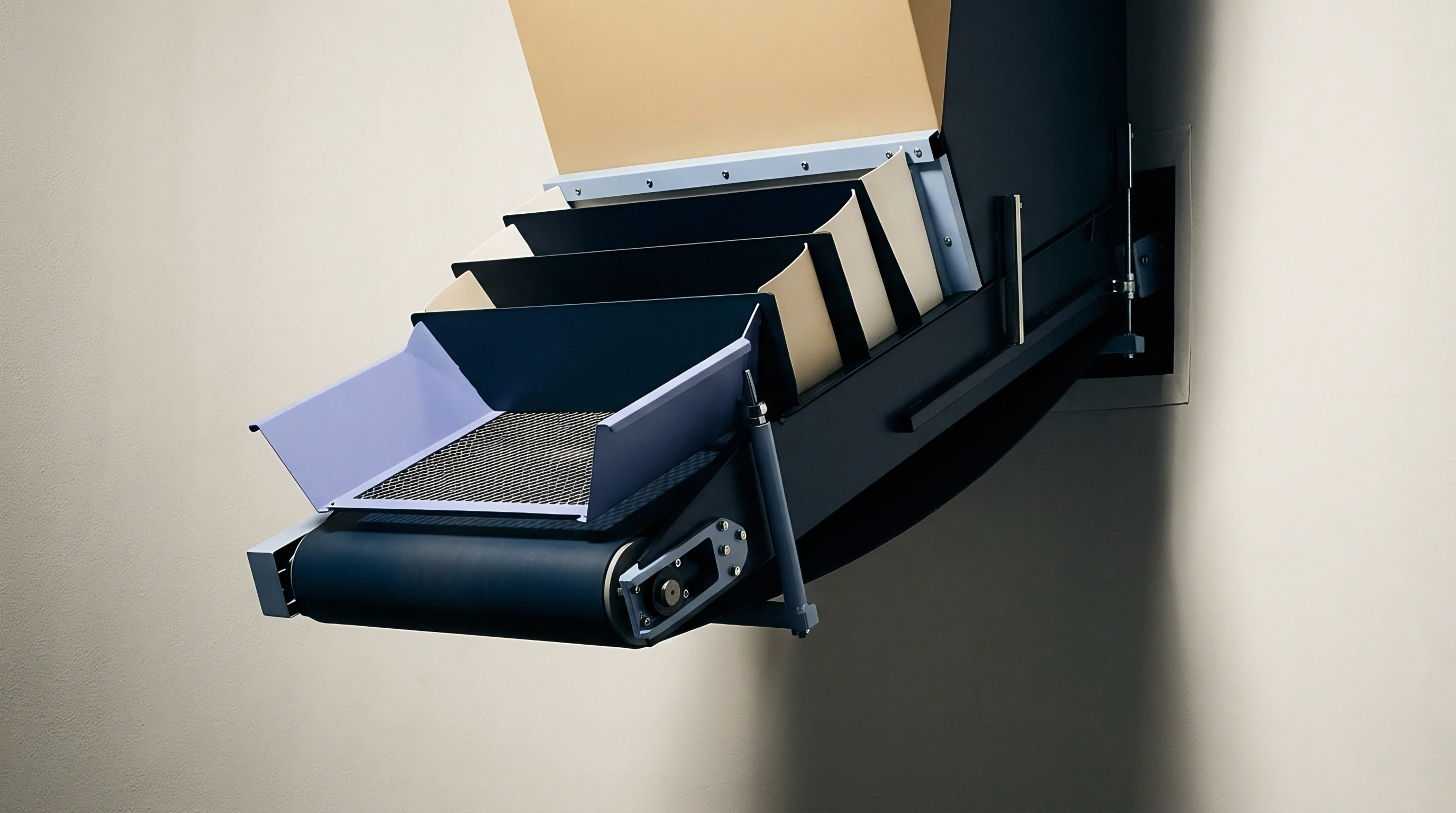
Width
Running paperboard through a die cutter at over 8,000 sheets per hour leaves no room for guesswork in aligning creasing rule thickness, substrate caliper, and counter matrix channel geometry. On modern flatbed platen presses, paperboard sheets are converted into carton blanks in milliseconds. Channel width determines whether the board forms a clean internal hinge or suffers outer liner fracture, internal ply shearing, or excessive opening resistance on automated gluing and filling lines.
Finding the right groove width starts with creasing rule base thickness and board caliper measured under ISO 187 conditions (23 degrees Celsius and 50 percent relative humidity).
Calculating channel width relies on adding creasing rule thickness to a set multiplier of board caliper. The standard formula for straight channels is:
W = W_r + (1.5 × T) for paperboard calipers under 0.38 mm (0.015 inches), and
W = W_r + (1.7 × T) for paperboard calipers equal to or exceeding 0.38 mm (0.015 inches),
where W is the clear internal width of the counter matrix channel in millimeters, W_r is the physical width of the steel creasing rule in millimeters, and T is the paperboard caliper measured under ISO 534 testing conditions. Fiber structure dictates how the board handles stress. Solid Bleached Board (SBB), made from long virgin chemical fibers, tolerates tight multipliers around 1.4 times caliper without rupturing.
Coated Recycled Board (CRB), made from shorter, re-pulped fibers, breaks under lower strain. Recycled grades require channel widths between 1.7 and 1.9 times sheet caliper to prevent outer score lines from tearing.
As the steel creasing rule forces paperboard into the channel, the board undergoes controlled delamination across its inner layers, creating a double hinge along the crease. If the channel is too narrow, the rule crushes the board against the matrix shoulders rather than driving it cleanly into the slot. That pinch shears printable clay coatings, leaving visible shear lines, flaking ink, and surface cracks.
If the channel is too wide, the rule fails to generate enough tension across inner plies. The board simply bows into the recess without delaminating, resulting in a weak crease with poor memory, panel bulging, and erratic folding resistance.
When winter storage drops plant humidity, paperboard loses caliper and gains stiffness, causing tight counter matrix channels to pinch and crack outer liners.
Steel creasing rules are specified by point size, where 1 point equals 0.356 mm (0.014 inches). A 2-point rule is 0.71 mm thick, while a 3-point rule measures 1.05 mm. Running 400-micron (0.40 mm) Folding Boxboard (FBB) with a 2-point rule calls for a channel width of 0.71 mm + (1.7 × 0.40 mm), or 1.39 mm.
Matrix suppliers manufacture channels in 0.10 mm increments, so a 1.40 mm channel provides the target operating window. Channel width is also evaluated relative to fiber orientation during stock qualification. Cross-direction (CD) creases endure higher mechanical strain because fibers lie perpendicular to the fold, requiring channels roughly 0.10 mm wider than those used for machine-direction (MD) creases on the same sheet.
Rule tip profiles also alter stress distribution during impression. Standard RD rules feature a fully rounded top where the radius equals half the rule width, giving a 2-point RD rule a 0.355 mm radius. Specialized shapes ~ such as trapezoidal, narrow-top, or off-center profiles ~ distribute strain differently across the sheet.
Above 9,000 sheets per hour, dynamic impact forces change board behavior: viscoelastic strain hardening makes the material act stiffer than static tests indicate. Channels chosen solely from slow press proofs often fracture scores once the press ramps up to speed.
Selecting channel width requires accounting for furnish construction. Folding Boxboard (FBB) sandwiches a bulky mechanical pulp core between outer layers of bleached chemical pulp. While that bulk adds bending stiffness, short mechanical fibers crush easily under localized pressure.
Matrix channels for FBB must encourage controlled Z-direction delamination rather than sharp displacement. By contrast, Solid Unbleached Board (SUB) and Coated Natural Kraft (CNK) rely on long, unbleached softwood fibers with high tear strength and energy absorption. Kraft grades tolerate narrow channels without liner splitting, enabling the tight folds needed for heavy beverage multipacks.
Sizing matrix channels to match substrate categories and caliper ranges prevents nuisance press stops during long production runs.
Recycled paperboards demand wider channel tolerances than virgin chemical boards of the same caliper.
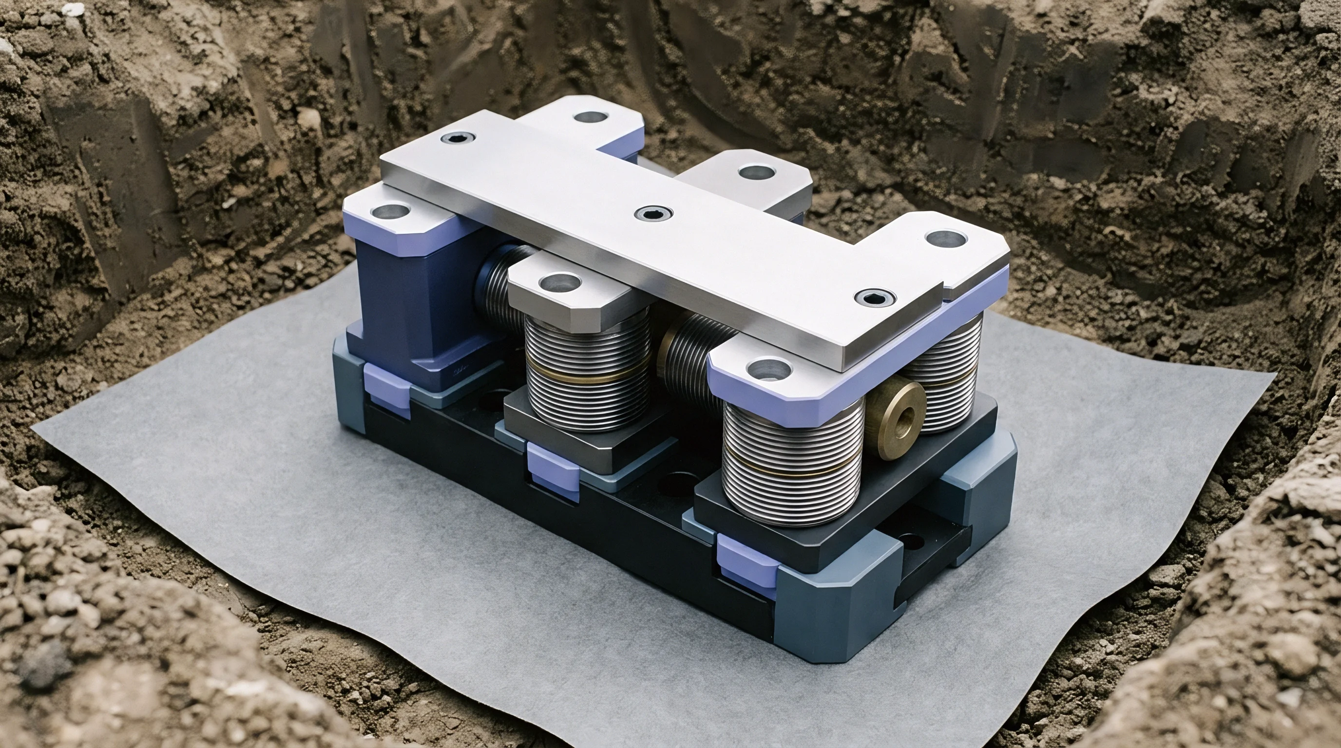
Groove
Channel depth determines how far paperboard deflects during platen dwell, and it must match sheet caliper closely. Shallow grooves cause the creasing rule to strike the bottom floor, crushing central plies and reducing caliper along the score root. Deep grooves leave the board unsupported, resulting in shallow creases, erratic fold angles, and jams on packaging equipment.
Target channel depth follows measured ISO 534 sheet caliper. Standard boards use a 1:1 ratio where depth D equals sheet caliper T. Dense, low-bulk grades like Solid Bleached Sulfate benefit from shallower depths around 0.9 × caliper to keep the top liner from overstretching.
High-bulk folding boxboards need depths closer to 1.1 × caliper to accept compressed mechanical fibers without creating high vertical pinch points.
Matrix materials differ in stability, edge life, surface friction, and resistance to heavy platen tonnage. Where pressmen once cut pressboard channels by hand, modern high-speed presses rely on three primary systems: self-adhesive prespaced synthetic channels, vulcanized fiber strips on steel bases, or CNC-milled solid steel counter plates. Each option balances setup time, thermal stability, wear life, and channel accuracy differently.
Milled steel counter plates offer the tightest tolerances for high-speed folding carton runs. Machined from 0.70 mm to 1.00 mm hardened steel or alloy sheets, their etched or milled channels match complex die layouts within ±0.005 mm. Entrance shoulders are chamfered between 30 and 45 degrees, allowing the sheet to draw into the groove smoothly without scuffing printable coatings or inducing web flutter at transfer.
| Matrix Material Type | Hardness (Shore D / HV) | Elastic Recovery (%) | Thermal Stability (mm/m/°C) | Maximum Sheet Cycle Rating |
|---|---|---|---|---|
| Standard PVC Matrix Strip | 65 Shore D | 72 | 0.080 | 50,000 |
| Modified Phenolic Resin Strip | 88 Shore D | 89 | 0.035 | 250,000 |
| Vulcanized Cotton Fiber Base | 92 Shore D | 84 | 0.025 | 400,000 |
| CNC Milled Steel Counter Plate | 240 HV | 99 | 0.012 | 3,000,000 |
Prespaced synthetic matrices made from modified PVC or phenolic resins offer fast make-readies for short and medium runs. Phenolic options handle heat much better than PVC. At 9,000 sheets per hour, friction between board and matrix walls can push surface temperatures past 50 degrees Celsius.
Standard PVC softens and creeps laterally under heat, widening the channel over a shift. A width increase of just 0.08 mm changes the crease stiffness ratio enough to cause sloppy folding and gluer misregistration. Phenolic strips maintain their geometry through long, warm runs.
Internal channel shoulder profile matters as much as width. Sharp 90-degree corners create stress points where shear forces concentrate, tearing bottom liner plies during impression. Precision steel counters use radiused internal corners (0.15 mm to 0.25 mm) to spread shear forces across plies, encouraging clean delamination without damaging outer printed surfaces.
Outer matrix shoulders also require low-profile external bevels between 9 and 15 degrees. These ramps keep fast-moving sheets from catching on matrix edges as they pass through the platen. Stubbed sheet edges trigger instant press stops, which can tear ejection rubbers, knock stripping pins out of alignment, and damage multi-up dies.
Beveled outer profiles maintain smooth sheet travel past 10,000 sheets per hour.
Internal bond strength is measured with TAPPI T541 before deciding on channel depth. Boards with low bond strength (under 150 kPa) need shallower grooves and wider channels to keep core plies from shearing apart during impact. High-bond boards (over 350 kPa) resist delamination and require precise bottom-dead-center pressure calibration to form complete creases without overloading press hydraulics or die components.
- Phenolic matrix selection provides high dimensional stability under high temperature platen runs exceeding two hundred thousand sheets.
- Steel counter plates eliminate long make-ready alignment procedures by locking exact channel positions relative to upper steel creasing rules.
- External shoulder beveling minimizes high-speed sheet edge contact, reducing press stops from sheet misfeeds.
- Internal groove radiusing prevents localized strain concentration, protecting delicate printed outer coatings from cracking.
Matrix wear often stems from excessive platen tonnage or poor counter alignment rather than abrasive board surfaces.
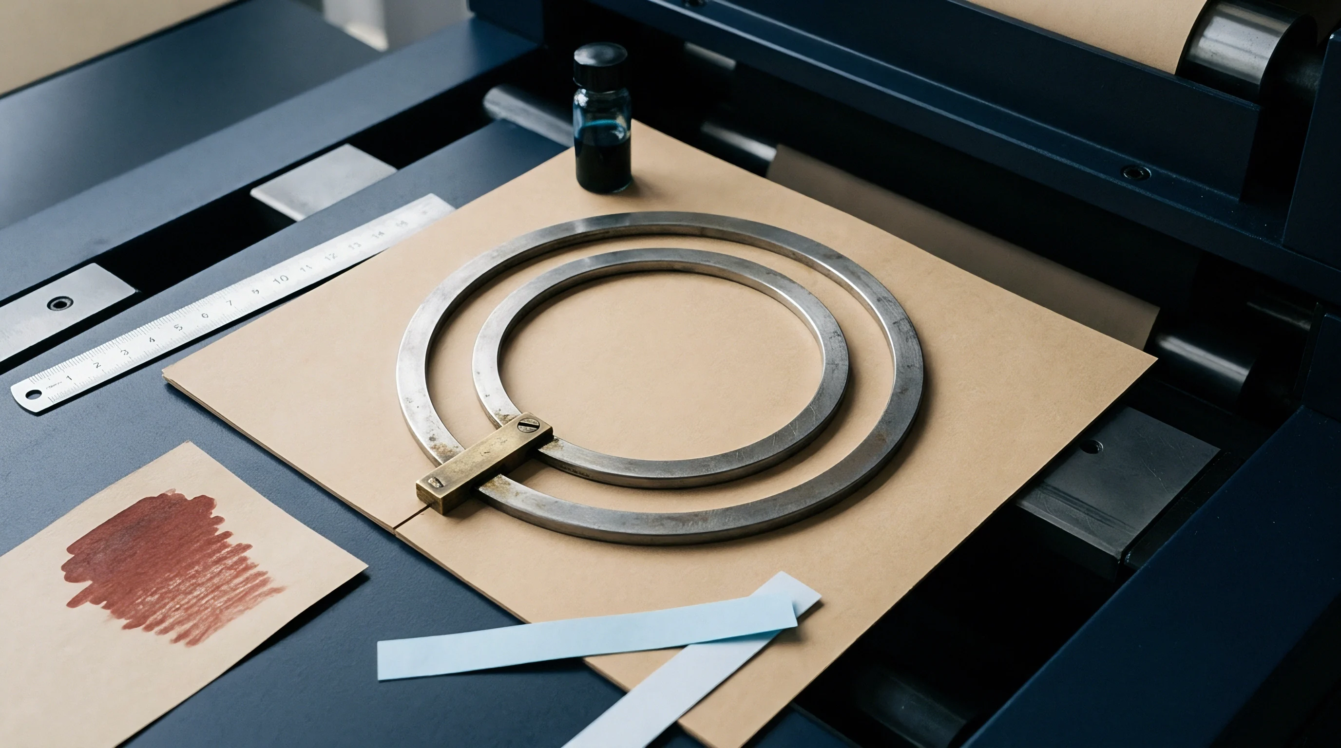
Stiffness
Paperboard behaves as an anisotropic material, with mechanical properties that vary across Machine Direction (MD), Cross Direction (CD), and Z-direction thickness. Bending stiffness (measured under ISO 2493 and TAPPI T556 at a standard 15-degree deflection) determines how the sheet reacts to localized bending. During die cutting, creasing rules apply fast shear and compression perpendicular to the sheet, forcing internal plies to yield in a controlled pattern that acts as a hinge.
Proper creases depend on controlled internal delamination. As the rounded rule pushes into the board, top plies compress while bottom plies stretching over the channel experience high tension. Vertical penetration generates shear stress along middle Z-direction plies.
In quality virgin boards, this shear breaks hydrogen bonds between fibers in the center layer, letting upper and lower liners slide past each other without rupturing. The result is a crease with low folding resistance and solid structural integrity.
Solid Bleached Sulfate (SBS) consists of dense chemical pulp layers with high internal bond strength (TAPPI T541). Because it resists delamination, setting matrix channels too wide causes SBS to flex as a single sheet rather than forming a clean crease line. The finished cartons get rounded edges, loose dimensions, and high spring-back that bows side panels during assembly.
Scoring SBS demands narrower channels and accurate rule penetration to break bonds within the tough chemical pulp layer.
Coated Recycled Board (CRB) behaves quite differently. Made from short, re-pulped fibers, CRB has low internal bond strength, lower strain-to-break limits, and poor moisture retention. These short fibers cannot stretch as far across the channel opening under tension.
Incorrect matrix geometry immediately cracks the outer liner, exposing raw gray fibers along printed folds. Scoring CRB requires wider matrix channels (up to 1.9 times sheet caliper) and larger rule radii to spread tensile strain over a wider area.
Board moisture heavily influences viscoelastic behavior at high press speeds. Conditioned at 50 percent relative humidity, paperboard holds 6.5 to 7.5 percent moisture by weight. Water acts as a natural plasticizer, keeping fibers flexible so hydrogen bonds break smoothly under shear.
If storage humidity drops to 30 percent, sheet moisture falls below 5.0 percent, leaving fibers stiff and brittle. Under rapid impact, dry board fails to delaminate internally; outer plies simply snap, causing widespread score cracking across the run.
- Outer liner cracking occurs when tensile strain across the bottom matrix channel exceeds the ultimate elongation limit of the bottom bleached kraft fibers.
- Internal ply crushing arises when excessive rule penetration forces core fibers against an undersized channel floor, destroying bulk stiffness.
- Shear line show-through happens when overly narrow matrix shoulders compress printable clay coatings, leaving permanent pressure marks along fold lines.
- Crease roll-over develops when asymmetrical matrix alignment pushes the creasing rule off-center, producing uneven fold resistance between panel faces.
Evaluating internal structural integrity requires analyzing the ratio between creased bending stiffness and uncreased bending stiffness. The crease stiffness ratio, expressed as a percentage, provides an objective measurement of creasing quality. It is calculated as:
C_r = (B_creased / B_uncreased) × 100
where B_creased is the force needed to bend a creased sample to 90 degrees, and B_uncreased is the force required to bend an uncreased sample of the same board to 90 degrees under ISO 5628 testing. Target crease stiffness ratios fall between 35 percent and 50 percent. Ratios above 65 percent mean the crease is under-formed, leaving rigid scores that jam packaging machinery.
Ratios under 20 percent indicate core crushing and structural damage, producing weak cartons prone to collapsing in storage.
A crease stiffness ratio exceeding sixty-five percent indicates incomplete internal delamination, generating high fold resistance that destabilizes high-speed packaging equipment.
Fiber alignment creates clear differences between Machine Direction (MD) and Cross Direction (CD) performance. Fibers align mostly parallel to machine travel, giving MD high tensile strength and stiffness while resisting bending across the fiber axis. CD features lower stiffness and higher stretch capability.
Creases parallel to MD (folding across the CD axis) use slightly narrower channels because transverse fibers delaminate easily. Creases running parallel to CD (folding across MD fibers) force long fibers to bend over channel shoulders, requiring wider channels and larger entry radii to avoid tearing.
Caliper variations across a paperboard reel add another variable. Cross-web thickness can drift by ±4 percent across a 1,600 mm reel, ranging from 384 to 416 microns on a nominal 400-micron board. Fixed matrix channels sized strictly for 400 microns will over-crease thick areas and under-crease thin spots.
Setting a reliable process requires choosing channel dimensions that accommodate the upper caliper limit while keeping crease stiffness within spec at the lower boundary.
Using improper channels on stiff virgin board leads directly to high fold resistance, forcing packaging lines to reject un-erected blanks and driving up downtime and scrap.
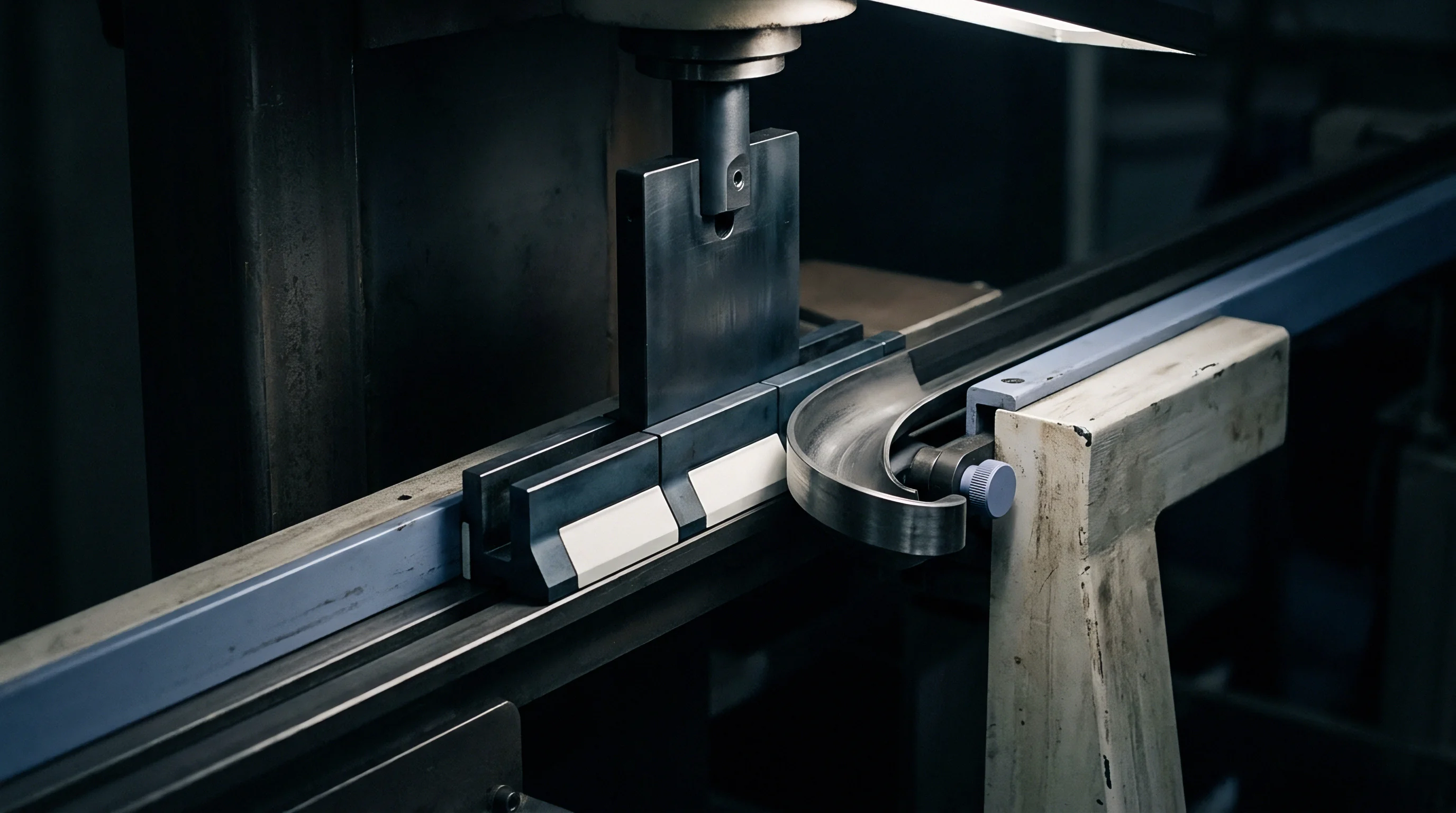
Velocity
Flatbed die cutters running between 8,000 and 11,500 sheets per hour shift the physics of creasing. Dwell time ~ the window at bottom dead center when creasing rules compress board into the counter plate ~ shrinks rapidly as press speed climbs. At make-ready speeds of 1,500 sheets per hour, dwell time sits around 80 to 100 milliseconds.
At 10,000 sheets per hour, that window drops to 12 to 16 milliseconds, fundamentally changing how cellulose fibers absorb stress.
Because paperboard is strain-rate sensitive, cellulose and lignin polymer chains do not have time to relax during high-speed compression strokes. Apparent bending stiffness and elastic modulus rise significantly at high impact speeds. Channels that yield clean creases during slow make-ready proofs often cause widespread liner cracking once the press hits production speed.
Fast displacement also traps pore air inside the sheet, creating transient pressure spikes that can blow out inner plies or cause root micro-fractures.
Dynamic platen deflection adds another layer of complexity. Modern presses apply 250 to 400 metric tons of force across sheets up to 1,060 mm by 760 mm. Even heavy cast-steel beds flex under high impact, deflecting slightly more in the center than near the outer corner pillars.
At full speed, central rule penetration decreases by 0.02 mm to 0.04 mm compared to static measurements. Tooling teams offset this by placing precision steel shimming sheets beneath counter plates or applying targeted make-ready tape behind the die base.
| Production Speed (Sheets/Hour) | Effective Dwell Time (ms) | Apparent Sheet Stiffness Shift (%) | Recommended Channel Width Offset | Recommended Channel Depth Offset |
|---|---|---|---|---|
| 2,000 (Make-Ready) | 75 – 90 | Baseline (0%) | Calculated Nominal (0.00 mm) | 1.00 × Caliper |
| 6,000 (Medium Run) | 25 – 32 | + 8% to + 12% | + 0.05 mm wider | 1.00 × Caliper |
| 9,000 (High Speed) | 16 – 20 | + 18% to + 24% | + 0.10 mm wider | 0.95 × Caliper |
| 11,000 (Peak Speed) | 12 – 15 | + 28% to + 35% | + 0.10 mm to + 0.15 mm wider | 0.90 × Caliper |
Continuous friction at high production speeds builds heat across the die cutting zone. Friction between board, steel rules, and matrix channels raises counter plate temperatures. Synthetic polymer matrices expand thermally, narrowing channel clearance as the shift progresses.
That tight clearance increases pinching forces, gradually degrading outer liners over long runs. Switching to phenolic resin, vulcanized fiber, or milled steel counters eliminates thermal channel shrinkage.
Should Converters Adjust Channel Width for High Speeds?
Optimizing counter matrix geometry for high press speeds requires practical trial and observation. Sizing channel parameters strictly during slow press inching cycles leads to errors; strain hardening at high speeds must be factored in right from CAD design.
- Position the die chase securely within the upper platen frame and verify registered locking torque values.
- Mount the pre-milled steel counter plate or phenolic matrix system onto the lower cutting platen sheet, ensuring absolute cleanliness of the mounting surface.
- Perform initial static rule-to-matrix alignment checks using low-density carbon transfer paper to confirm precise lateral centering of creasing rules within female channels.
- Execute sample impression strikes at slow make-ready speeds (1,500 sheets per hour) to verify basic rule penetration depth and initial crease clearance.
- Accelerate the press in controlled increments to target operational velocity (e.g. 9,000 sheets per hour) and harvest intact carton blanks from the delivery stacker.
- Conduct immediate 90-degree fold resistance testing and cross-sectional optical inspection on high-speed samples to verify internal delamination and liner integrity.
- Apply micrometer impression adjustments across platen quadrants to compensate for speed-dependent dynamic platen frame flexing.
Mechanical vibration at peak speed introduces slight lateral register float (roughly ±0.03 mm). If matrix channel entry chamfers are too tight, rules strike off-center against channel shoulders. Off-center impact creates asymmetrical creases, chews up matrix edges, and produces tiny metal shavings that contaminate printed sheets.
Wider entry chamfers (30-degree bevel angles) accommodate high-speed register float and guide rules cleanly into the channel.
Proper press alignment keeps tooling alive. High speeds exacerbate any misalignment between the die chase and counter plate. Phenolic counter plates are specified for folding boxboard orders exceeding one hundred thousand sheets to withstand repeated dynamic impacts.
Building speed adjustments directly into initial matrix design cuts back on manual make-ready tweaking at the press.
What unmeasured dynamic interplay occurs between transient internal pore-air compression and cellulose fiber bond breaking during the 12-millisecond impact window of an 11,000 sheet-per-hour die cutting stroke?
Margin
Packaging conversion runs on thin margins where material yield, tooling life, make-ready times, and press efficiency decide profitability. While paperboard accounts for 55 percent to 70 percent of carton cost, counter matrix choice controls downtime, waste, and hourly operating expenses. Sourcing engineers and procurement managers need to evaluate matrix tooling through complete operating cost models rather than looking only at initial invoice prices.
Consider a representative high-volume commercial packaging run: 500,000 folding cartons produced from 450-micron (0.45 mm) Folding Boxboard (FBB) with a sheet size of 1,020 mm × 720 mm, running 12 carton blanks per sheet (41,667 total press impressions). The die cutting operation is scheduled on a modern 10,600 sheet-per-hour automated flatbed press with an operating rate of $280 per hour. The substrate cost is $1,450 per metric ton ($1.45 per kg).
At a sheet weight of 240 grams per square meter (0.1763 kg per sheet), total substrate material cost for the run equals $10,654.
The financial breakdown compares two tooling implementation strategies for this production run: Strategy A utilizes low-cost self-adhesive PVC matrix strips manually applied by press operators; Strategy B utilizes a custom CNC-milled steel counter plate engineered with chamfered, radiused channels.
| Operational Cost Element | Strategy A: PVC Matrix Strips | Strategy B: Milled Steel Counter | Variance / Savings (Strategy B) |
|---|---|---|---|
| Initial Tooling / Matrix Invoice Cost | $120 | $850 | -$730 (Higher initial cost) |
| Make-Ready & Alignment Time | 1.75 hours ($490) | 0.35 hours ($98) | +$392 (Downtime saved) |
| Running Production Speed (Average) | 6,800 sheets/hour | 9,500 sheets/hour | +2,700 sheets/hour faster |
| Total Press Running Hours | 6.13 hours ($1,716) | 4.39 hours ($1,229) | +$487 (Machine time saved) |
| Matrix Wear Replacement Stops | 1 stop; 0.75 hrs ($210) | 0 stops ($0) | +$210 (Eliminated downtime) |
| Make-Ready & Process Scrap Sheets | 1,400 sheets ($247) | 350 sheets ($62) | +$185 (Substrate saved) |
| High-Speed Score Failure Scrap (Gluing) | 2.2% scrap ($234) | 0.3% scrap ($32) | +$202 (Finished product saved) |
| Total Net Conversion & Tooling Cost | $3,467 | $2,501 | +$966 Net Cost Reduction (27.8%) |
The financial breakdown shows that investing in precision steel tooling delivers real net savings. Strategy B cuts job conversion costs by $966 despite an initial tooling cost $730 higher. Downtime reduction accounts for most of the gain.
Manually placing self-adhesive matrix strips across a 12-up die takes over 1.5 hours of press time. Steel counter plates drop into pin-registration on the lower plate in 20 minutes, opening up capacity across daily job turnarounds.
Matrix wear adds costs fast on longer runs. PVC strips break down under repeated impact. Between 25,000 and 30,000 impressions, channel entry shoulders wear down, widening the groove.
That widening drives crease stiffness ratios from a clean 42 percent up to 68 percent. When those cartons reach automated high-speed gluers running at 400 to 600 units per minute, stiff scores refuse to fold properly, causing feeder jams, customer downtime, and costly quality claims.
In plant trials, matrix shoulder erosion exceeded twelve percent after three hundred thousand impressions when using un-reinforced polymer channels on coated recycled board.
Board waste from bad channel geometry drains margins directly. Cracking outer liners forces operators to stop the press, adjust tonnage, apply patch tape, or pull degraded matrix strips. Every minute of stoppage wastes press capacity, and ruined sheets add up quickly.
Lowering sheet scrap from 1,400 to 350 saves $185 in stock on a single job while keeping waste off the floor.
Tooling longevity changes the math on repeat work. Precision steel counters endure over 3,000,000 impressions without measurable channel widening or edge wear. For ongoing SKUs in pharma, food, or beverage packaging, one counter plate covers multiple runs over several years.
Amortizing an $850 steel counter across 2,000,000 cartons brings tooling cost to $0.000425 per box, making upfront price negligible compared to press savings.
- Standardized channel sizing documentation must accompany all counter tooling orders, specifying exact width, depth, chamfer angle, and radius parameters.
- Substrate-specific matrix design rules must be embedded within CAD/CAM tooling software to automatically assign matrix channels based on board caliper and furnish type.
- Pin-registration tolerance specifications must mandate positional accuracy within ±0.005 mm across the entire lower counter plate surface.
- Steel counter plate hardness requirements must specify minimum surface hardness of 220 HV to prevent localized indentation under high-tonnage rules.
Make-ready scrap erodes profit. Defining tight procurement specifications for tooling keeps converting costs predictable. Tooling orders should explicitly state tolerances, chamfer requirements, and material hardness standards.
Standard purchase contracts for commercial die cut tooling must incorporate the clause: “Counter matrix channel dimensions shall be CNC-milled to within ±0.005 mm of CAD specification, utilizing hardened steel plate stock certified to a minimum hardness of 220 HV, and shall guarantee dimensional stability without channel shoulder erosion exceeding 0.02 mm over one million press impressions.”
Control
Maintaining converting consistency over long runs requires systematic testing during incoming stock inspection and press make-ready. Paperboard is a natural polymer structure whose caliper and stiffness shift with plant humidity, batch changes, and mill setups. Checking board caliper, internal bond strength, and bending stiffness before mounting die tooling prevents high-speed failures before they happen.
Standard test methods give reliable data on raw board and finished creases. Measuring caliper under ISO 534 uses a dead-weight micrometer applying 100 kPa across a 2.0 cm² anvil, with readings taken from the drive-side, center, and operator-side of incoming stock. Checking internal bond via TAPPI T541 (Z-direction tensile testing) measures core shear resistance, providing the foundation for setting channel depth.
| Quality Parameter | Standard Test Method | Target Range / Threshold | Operational Action on Variance |
|---|---|---|---|
| Board Caliper Uniformity | ISO 534 / TAPPI T411 | Nominal ± 3% max drift | Adjust channel width if drift exceeds ± 5% |
| Z-Direction Tensile (Bond) | TAPPI T541 / ISO 15754 | 180 – 350 kPa (FBB / SBS) | Deepen matrix depth by 0.05 mm if > 380 kPa |
| Crease Bending Resistance | ISO 5628 / TAPPI T577 | 35% – 50% Crease Ratio | Widen channel if ratio exceeds 60% |
| Outer Liner Cracking Score | Visual at 50× Magnification | Zero visible fiber tears | Increase rule tip radius or widen matrix |
| Crease Symmetry Index | Cross-section Microscopy | Channel Centering ± 0.02 mm | Re-align counter plate registration pins |
Press-side evaluation relies on quick physical testing during make-ready and sampling. Instruments like the L&W Crease Proof Tester or Marbach Crease Control measure the force needed to bend a creased sample 90 degrees in 1.5 seconds. Comparing creased resistance to raw board stiffness yields the crease stiffness ratio.
Keeping that ratio between 35 percent and 50 percent ensures predictable folding on cartoning equipment without losing box strength.
Cross-sectional microscopy offers clear diagnostics of internal delamination. Microtome samples viewed at 50× magnification show whether inner plies have delaminated cleanly. An ideal crease forms a balanced internal pocket without cracking outer coatings or tearing bottom liners.
Asymmetrical delamination points to lateral misalignment between rule and channel, signaling an immediate need for counter plate re-registration.
Score cracking ruins finished print. Routine incoming moisture checks (ISO 287) keep brittle stock off the press. If incoming board reads below 5.5 percent moisture, holding pallets in a controlled environment (23°C, 50% RH) for 48 hours restores fiber flexibility, allowing target matrix settings to work as intended.
Rigorous quality protocols ~ from tooling specs to incoming board inspection and press-side testing ~ give plants reliable control over high-speed packaging conversion.