Paperboard Caliper and Rule Width Selection Formulas for Creasing Matrix Channel Optimization
Matrix channel width equals creasing rule thickness plus board caliper multiplied by grade constants ranging from 1.4 for SBB to 1.7 for WLC.
Geometry
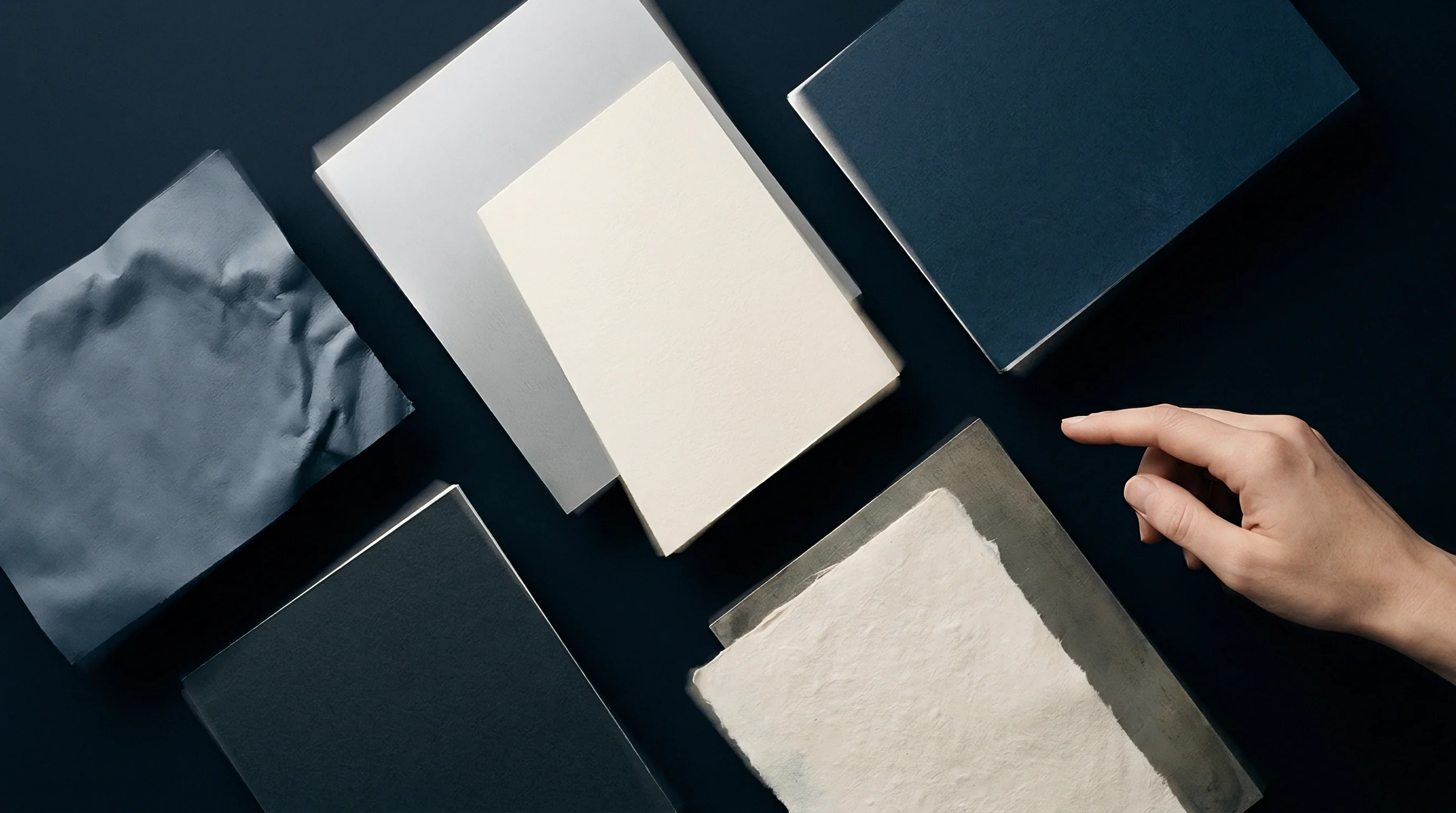
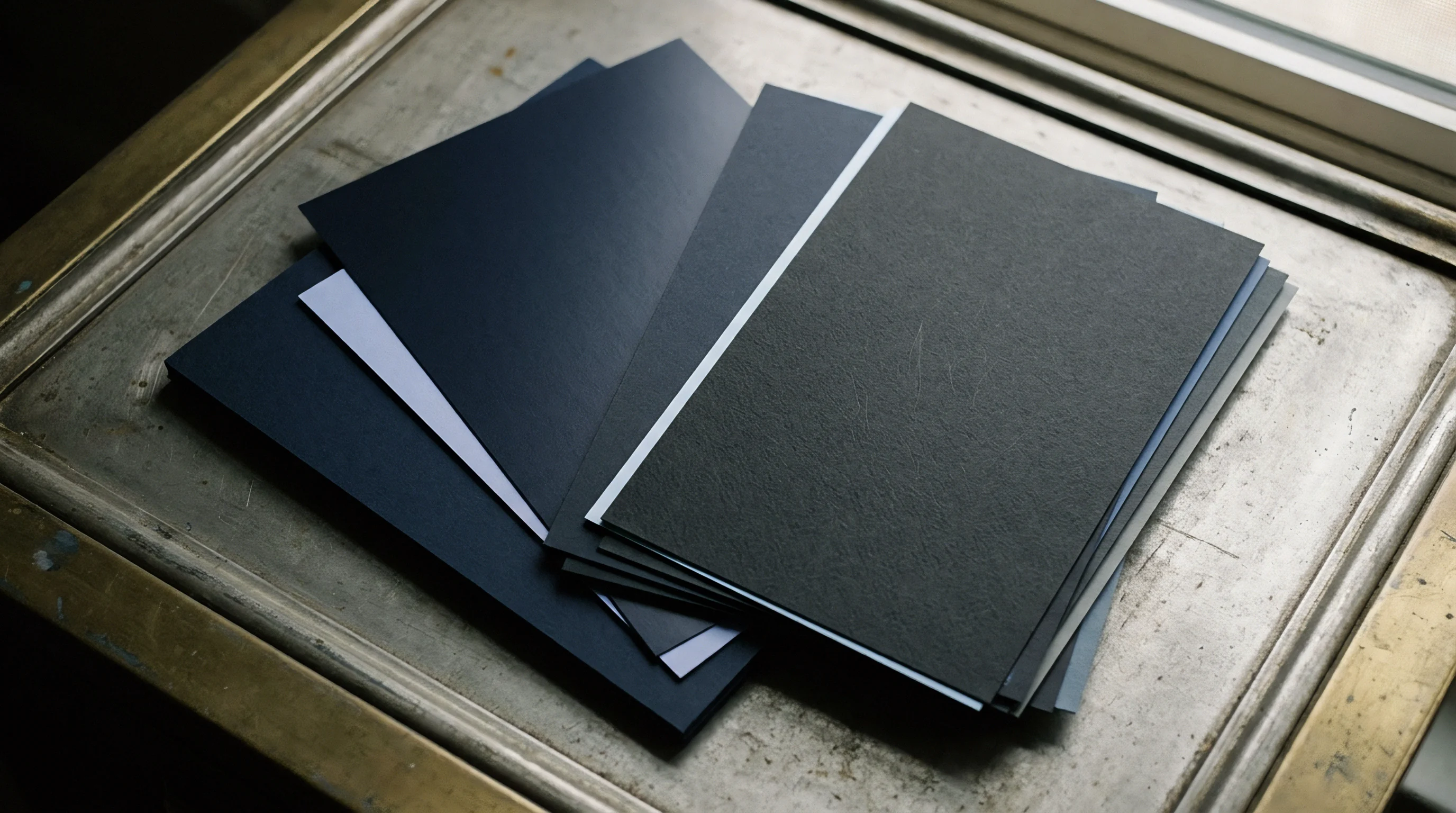
Board thickness drives creasing geometry. The mathematical calculation of creasing matrix channel dimensions requires a precise relationship between paperboard caliper, creasing rule thickness, and matrix geometry. During die-cutting, the steel creasing rule forces the paperboard into the matrix channel, initiating controlled internal shear failure.
This deformation creates a permanent paperboard hinge. Selecting channel dimensions without exact mathematical formulas risks either external liner rupture or insufficient shear delamination within the board layers.
The matrix channel width calculation relies on paperboard caliper and creasing rule thickness. The basic geometric equation defines channel width as the rule thickness plus twice the board clearance factor. Formula constants vary based on furnish elasticity and board density.

Mathematical Foundation of Crease Channel Dimensions
The baseline formula for creasing matrix channel width establishes the theoretical spatial clearance needed for paperboard displacement without surface tension failure. In standard packaging metrics, board thickness appears as caliper measured under ISO 534 protocols using a static load of fifty kilopascals.
Formula constant definitions establish the spatial relationship:
Matrix Width = Rule Thickness + (Clearance Multiplier x Caliper)
Matrix Depth = Board Caliper x Compression Factor
Standard creasing rule thickness options follow point-system designations translated into decimal millimeters. A two-point rule measures zero point seven one millimeters. A three-point rule measures one point zero five millimeters.
A four-point rule measures one point four two millimeters. Steel rules require exact sizing.
Selecting channel width based on substrate thickness prevents surface cracking while maintaining fold squareness.
Standard Empirical Matrix Sizing Equations
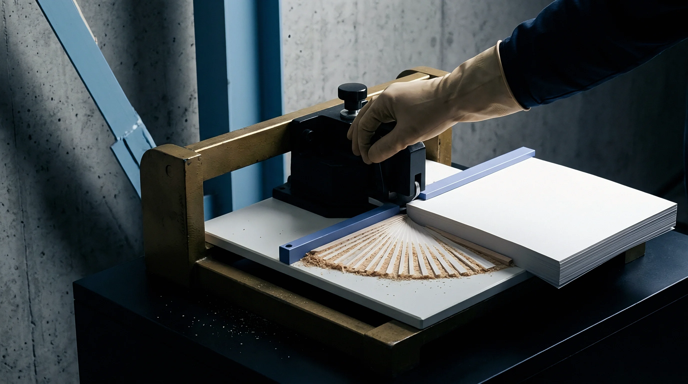
Solid Bleached Board furnishes demand a tight clearance multiplier due to long, intact virgin fibers. White Lined Chipboard requires wider channel clearance to prevent outer liner splitting caused by short recycled fibers with lower tensile strain limits. The standard empirical formula for solid bleached cartonboard sets the channel width at creasing rule thickness plus one point five times board caliper.
Matrix depth matches board caliper directly.
| Paperboard Grade Type | ISO 534 Caliper Range (mm) | Rule Thickness (pt / mm) | Width Formula (W) | Depth Formula (D) |
|---|---|---|---|---|
| Solid Bleached Board (SBB) | 0.20 – 0.50 | 2 Pt / 0.71 mm | W = tr + 1.4 t | D = 1.0 t |
| Folding Boxboard (FBB) | 0.30 – 0.65 | 2 Pt / 0.71 mm | W = tr + 1.5 t | D = 1.0 t |
| White Lined Chipboard (WLC) | 0.35 – 0.80 | 3 Pt / 1.05 mm | W = tr + 1.7 t | D = 1.1 t |
| Coated Unbleached Kraft (CUK) | 0.40 – 0.90 | 3 Pt / 1.05 mm | W = tr + 1.5 t | D = 1.0 t |
Formulas adjust automatically when moving to microflute corrugated substrates. F-flute and E-flute boards require compressed caliper values inside calculations to avoid crushing adjacent flute structures during impact.
General converting practice dictates matching the matrix channel depth to board caliper within a tight five percent tolerance band.


Mechanics
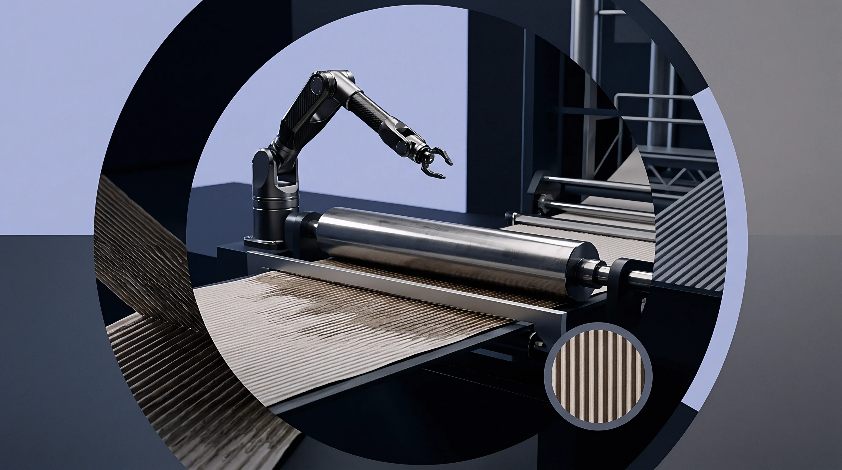
Delamination creates internal board hinges. The creasing operation transforms a rigid, monolithic sheet of paperboard into a flexible joint through localized shear failure across internal plies. As the creasing rule descends into the matrix channel, it imposes severe z-directional compressive force alongside shear stresses along the crease shoulders.
Delamination splits internal fiber bonds into thin, detached layers. These separated plies buckle individually toward the inner radius of the crease during ninety-degree or one-hundred-eighty-degree folding, drastically reducing bending resistance.
Direct mechanical failure occurs when matrix channels fall below minimum width limits. Narrow channels increase lateral compression forces beyond sheet limits, causing surface liner cracking along the top crease edge.
Internal Delamination and Shear Deformation Physics
Paperboard creasing requires balanced delamination across middle plies while preserving outer printable liners intact. Machine direction orientates more fibers parallel to the creasing line, increasing tensile stiffness and altering shear resistance. Cross direction creases cross a majority of perpendicular fibers, requiring larger energy inputs for complete ply separation.
Fiber length dictates shear stress.
The initiation of delamination depends directly on z-direction tensile strength measured via ISO 1924 methods. High-density solid bleached boards exhibit uniform z-tensile distribution, enabling clean, multiple internal splits. Multi-ply folding boxboards contain mechanical pulp centers with lower z-directional strength.
The mechanical core shears easily, absorbing rule penetration forces while high-strength chemical outer plies retain complete surface integrity.
A ten percent reduction in relative humidity below fifty percent increases bending stiffness by eight percent and elevates surface cracking frequency.

Z-Direction Tensile and Shear Stress Distributions
Rule penetration depth dictates the extent of internal ply separation. Insufficient rule penetration generates incomplete delamination, producing high residual bending torque that resists folder-gluer operations. Excessive penetration drives the creasing rule through the bottom liner, causing score shearing or matrix channel bottom failure.
Substrate moisture content governs fiber network elasticity during shear loading. Dry paperboard exhibits high elastic modulus with minimal plastic strain capability, resulting in premature liner fracturing. Moist paperboard deforms elastically without reaching critical delamination thresholds, leaving high crease stiffness.
Maintaining pressroom ambient conditions according to ISO 187 standards stabilizes fiber moisture states near seven percent water weight.
Inadequate channel widths generate excess shear stress along the crease walls, forcing top liner fibers to rupture, which results in rejected packaging lots and severe press downtime.
Calculation
Steel rules require exact sizing. Converting engineers execute matrix selection through systematic numerical evaluation of measured board caliper and targeted crease force profiles. Standardizing formulas across die-cutting production lines eliminates operator guessing and reduces setup scrap volumes.
The following worked examples demonstrate step-by-step sizing calculations across standard paperboard calipers.
Calculations begin with direct measurement of paperboard stock using an ISO 534 dead-weight micrometer across ten web points to establish mean caliper.

Worked Channel Sizing Models for Standard Calipers
Consider a folding carton packaging line running a zero point four five millimeter Folding Boxboard grade using a standard two-point creasing rule. Rule thickness equals zero point seven one millimeters. The baseline matrix width equation applies:
W = 0.71 mm + (1.5 x 0.45 mm)
W = 0.71 mm + 0.675 mm = 1.385 mm
Commercial matrix channels sell in standardized nominal widths. The engineer selects a standard one point four zero millimeter matrix channel width. The matrix depth formula uses a one-to-one ratio against board caliper:
D = 1.0 x 0.45 mm = 0.45 mm
The baseline tooling spec calls for a 0.45 x 1.40 mm creasing matrix strip.
| Board Caliper (mm) | Rule Thickness (mm) | Calculated Width (mm) | Selected Matrix Width (mm) | Selected Matrix Depth (mm) |
|---|---|---|---|---|
| 0.30 | 0.71 | 1.130 | 1.10 | 0.30 |
| 0.40 | 0.71 | 1.270 | 1.30 | 0.40 |
| 0.50 | 0.71 | 1.410 | 1.40 | 0.50 |
| 0.60 | 1.05 | 1.950 | 1.90 | 0.60 |
| 0.70 | 1.05 | 2.100 | 2.10 | 0.70 |
| Calculations utilize W = tr + 1.4 t for SBB grades up to 0.50 mm and W = tr + 1.5 t above 0.50 mm. | ||||

Tolerance Bands and Machine Drift Sensitivity
Paperboard mills operate within basis weight and caliper tolerances of plus or minus five percent across production runs. Caliper drift alters the effective clearance factor within fixed creasing matrix setups. A zero point five zero millimeter sheet drifting upward to zero point five two five millimeters increases channel filling by five percent, elevating shear stress across crease shoulders.
DIN 19306 specifies paperboard creasing test conditions at twenty-three degrees Celsius and fifty percent relative humidity to establish baseline force parameters.
When caliper drift exceeds six percent above target baseline, rule penetration adjustments become necessary to prevent liner shearing. Lowering cutting platen tonnage by twenty microns restores target clearance without changing matrix strips.
Formula adjustments must account for cross-direction orientation where bending stiffness increases by up to one hundred percent compared to machine direction lines.

Substrates
Furnish compositions alter crease mechanics. Fiber origin dictates how paperboard structures respond to mechanical strain during die penetration. Virgin chemical fibers feature high flexibility and unbroken inter-fiber bonds, sustaining steep deformation angles without surface cracking.
Mechanical pulps provide bulk and stiffness but possess lower elongation limits. Recycled fibers undergo multiple processing loops, shortening individual fibers and diminishing internal bond capabilities.
Coated board surfaces introduce secondary brittleness factors. Pigment coatings containing calcium carbonate or kaolin clay layer binders fracture easily if underlying fiber structures yield prematurely under localized crease rules.

Fibre Architecture and Recycled Content Dynamics
Solid Bleached Board layers consist entirely of chemical pulp. This uniform architecture allows tight matrix channel selection without threatening outer liner integrity. Folding Boxboard utilizes chemical pulp top and bottom layers over a mechanical pulp core.
The mechanical core yields early under compression, creating an internal cavity that allows smooth outer liner flexure.
White Lined Chipboard relies heavily on post-consumer recycled fiber networks. Shorter fiber length reduces shear strain resistance, forcing engineers to widen matrix channel clearances by ten to fifteen percent compared to virgin SBB metrics. Broader channels reduce shear stress concentration along vulnerable recycled top liners.
Unbleached kraft furnishes absorb shear forces without surface fracture more effectively than high-filler recycled grades.

How Does Moisture Content Alter Matrix Depth Selection?
Humidity shifts sheet dimensions quickly. Paperboard Equilibrium Moisture Content varies directly with ambient pressroom relative humidity. Dry paperboard below five percent moisture content hardens internal hydrogen bonds, making fibers brittle and highly sensitive to shear fracturing.
Damp board above nine percent moisture content softens internal bonds, causing excessive board compression without crisp delamination lines.
Matrix depth calculations require compensation when converting under non-standard relative humidity environments. Dry pressrooms mandate a five percent increase in channel width to offset reduced substrate elongation capacity. Wet pressrooms require deeper channel profiles to force delamination through supple, high-moisture plies.
Converters routinely blame substrate mills for board cracking during winter months when unconditioned warehouse storage drops internal board moisture levels below critical operational thresholds.


Tooling
Tooling wear widens score channels. Commercial creasing matrix products use extruded phenolics, vulcanized rubbers, pressboard, or synthetic polymer channels mounted on flexible steel bases. Matrix channel accuracy dictates repeatability across million-impression production runs.
Counter-plates milled directly from solid steel or steel-milled composite boards offer superior channel depth consistency compared to press-applied adhesive matrix strips.
Creasing rule geometry alters initial force distribution. Broad chamfered bevel rules reduce cutting actions on top liners, whereas round-nosed bevel rules distribute load evenly across high-density solid unbleached kraft substrates.

Matrix Composition and Counter-Plate Mechanics
Pressboard matrix products provide cheap, rapid press setup options for short run carton work. Phenolic and synthetic polymer matrix strips resist edge wear under high die-cutting pressures, maintaining channel shoulder crispness over three hundred thousand impressions. Milled steel counter-plates provide unyielding channel walls, making them mandatory for high-speed automated die-cutters processing long-run beverage carriers.
| Tooling Material Type | Channel Wear Resistance | Setup Time (Minutes) | Max Impression Life | Relative Unit Cost |
|---|---|---|---|---|
| Pressboard Strip | Low | 15 – 20 | 50,000 | 1.0 |
| Synthetic Polymer | Medium | 15 – 20 | 250,000 | 2.5 |
| Phenolic Resin Strip | High | 15 – 20 | 500,000 | 4.0 |
| Milled Steel Counter | Extreme | 45 – 60 | 2,000,000 | 12.0 |
Rule Bevel Angles and Penetration Speeds
Standard creasing rules utilize centered round crown profiles with radii optimized for specific board thickness groups. A two-point rule features a zero point three five millimeter crown radius. Sharp chamfered edge transitions cause micro-fractures along top clay coatings during impact.
Production steps for mounting creasing matrix systems follow strict physical alignment sequences to guarantee score center accuracy:
- Clean cutting platen surface with volatile degreasing solvent to eliminate residual oil films.
- Locate die cutting plate centrally over press chase locate pins.
- Press individual matrix locator channels onto steel creasing rules in cutting die.
- Peel protective release paper strips from matrix pressure-sensitive adhesive backings.
- Inching platen press through bottom dead center to transfer matrix channels onto counter plate.
- Remove plastic locator bridges gently to reveal open matrix channels aligned with rule centers.
ISO 12647 precision standards mandate matrix location accuracy within twenty-five microns across the entire die area to ensure uniform fold resistance.

Defects
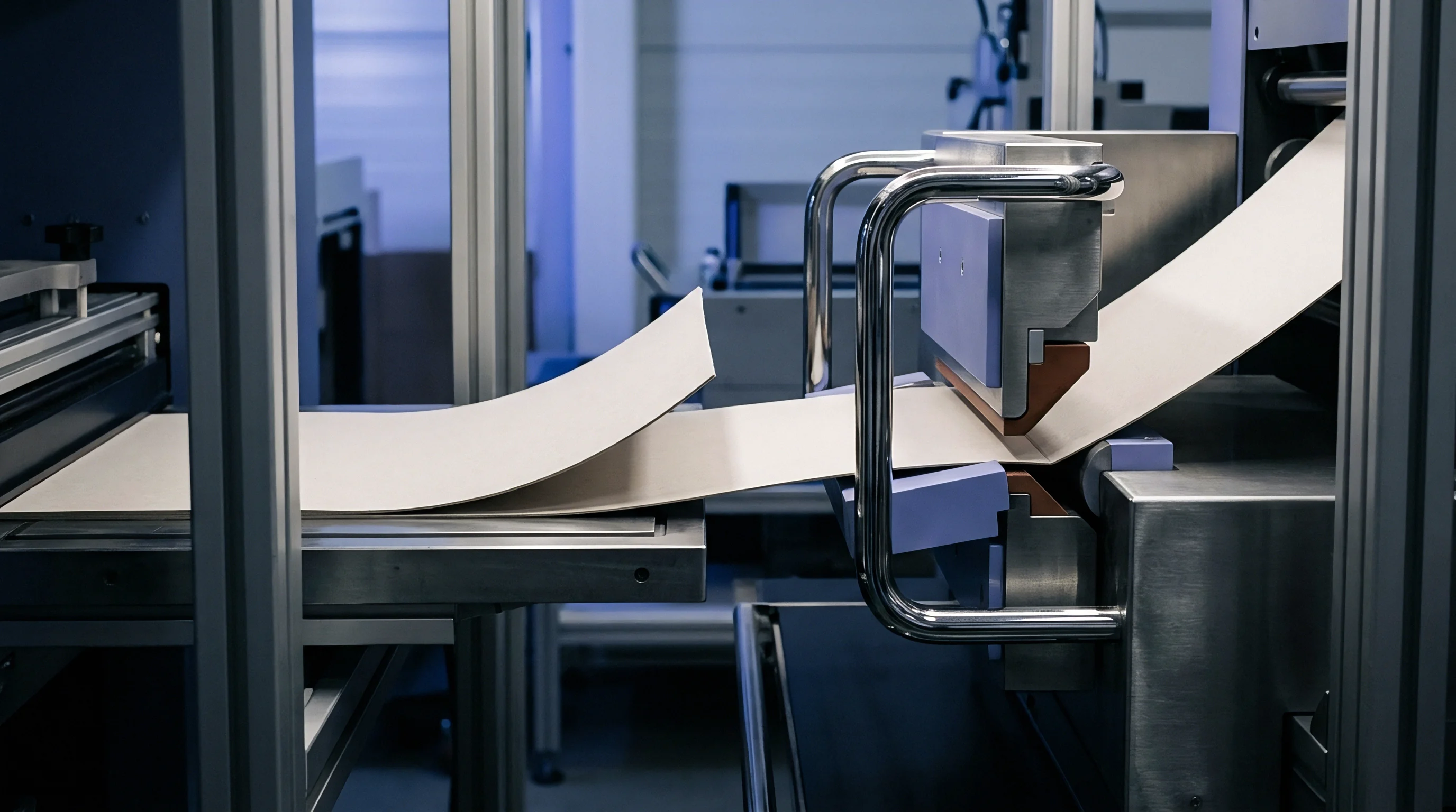
Folder gluers demand stable creases. Faulty matrix sizing generates distinct failure modes during converting operations. Score rupture occurs when narrow channel width or excessive rule depth shears surface fibers completely.
Bead rollover happens when overly wide channels allow the formed crease bead to shift laterally, producing crooked carton folds and uneven glue lap positioning. Excessive crease stiffness forces folder-gluer belts to drop line speeds, driving up operational costs.
Defect tracking requires isolating mechanical tooling errors from paperboard material variations at the die-cutting press input stage.
Root Causes of Score Rupture and Bead Rollover
Score rupture directly undermines carton structural integrity. Ruptured top liners expose raw fibers, causing ink cracking along fold edges that degrades visual packaging appeal. Bead rollover alters finished carton geometry, causing squareness deviations during high-speed packing line operations.
Common creasing matrix failure modes exhibit distinct physical signatures:
- Liner fracturing originates from narrow matrix channels, excessive rule penetration depth, or dangerously low paperboard relative humidity levels.
- Asymmetric crease beads stem from misaligned matrix locators, worn rule tips, or lateral counter-plate movement during press operation.
- Double crease impressions occur when matrix shoulder bases flex under tonnage load, leaving secondary compression tracks beside primary score channels.
- Unbroken crease stiffness indicates insufficient rule height, loose channel width clearances, or high furnish elasticity resisting internal delamination.
Folder-Gluer Resistance Torque Failures
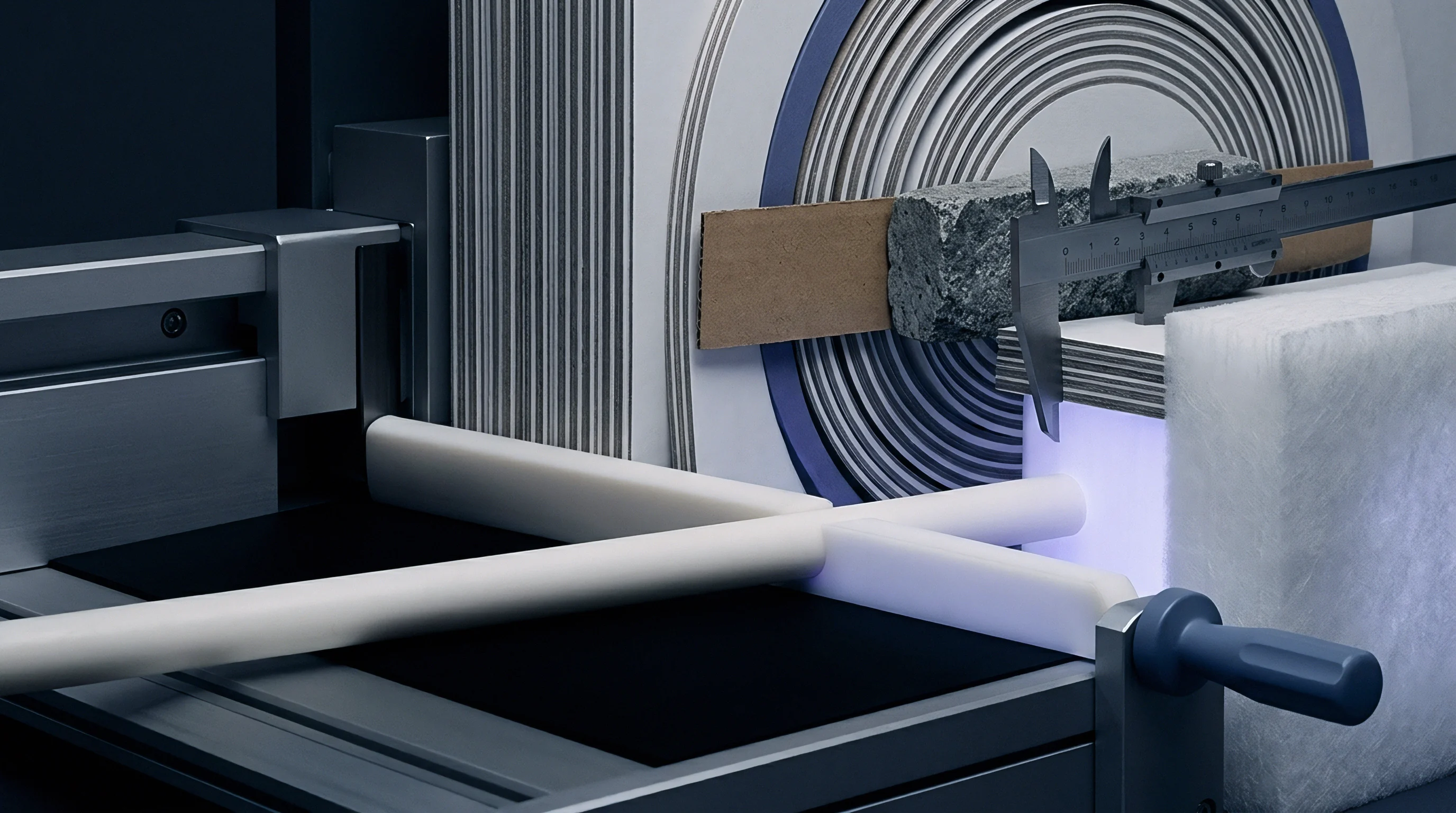
Automated packaging equipment demands consistent crease opening forces evaluated via TAPPI T 577 bending resistance testing. High opening force forces carton blanks to bow outward during side-seam folding, causing misfeeding jams inside folder-gluer transfer sections.
Converting engineers verify matrix installation validity through systematic quality audits:
- Caliper verification ensures incoming substrate batches match baseline matrix formula assumptions within target five percent bands.
- Channel width auditing checks matrix wear using optical measuring microscopes after every fifty thousand die-cutting impressions.
- Crease stiffness testing quantifies bending moment force values on ninety-degree folded samples pulled directly from press runs.
- Visual surface inspection confirms zero micro-cracking along coated liner surfaces under ten-times magnification optics.
Whether dynamic shear stress modeling can accurately predict matrix channel shoulder wear rates under high-speed converting conditions remains an open industry question.