Determining Matrix Channel Width for Heavyweight Folding Boxboard Grades
Determining matrix channel width requires adding steel rule thickness to board caliper multiplied by 1.5 for machine direction or 1.7 for cross direction scores.
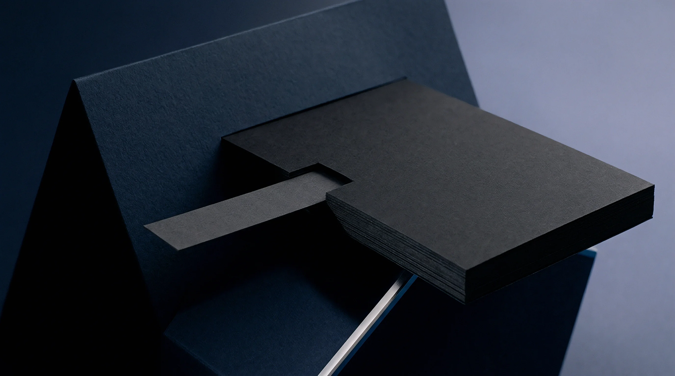
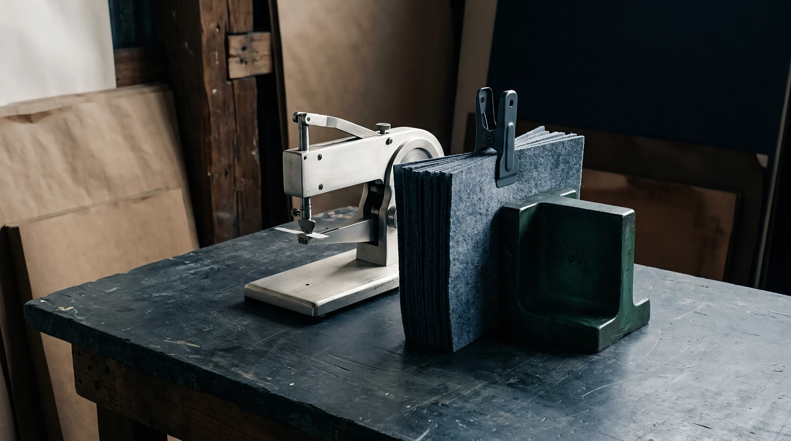
Caliper
Heavyweight folding boxboard grades ranging from 350 to 600 grams per square meter present distinct mechanical challenges during the creasing process. Board thickness dictates matrix width. Multi-ply GC1 and GC2 structural boards combine bleached chemical pulp outer layers with a dense thermo-mechanical pulp core.
When the creasing rule hits the board, it initiates controlled internal delamination along predetermined shear planes while preserving the integrity of the top clay coating and bottom liner.
Substrate thickness defines the baseline. Heavyweight folding boxboard measures between 450 and 850 micrometers in thickness, demanding distinct deformation dynamics compared to lightweight paperboard. Creasing does not merely bend the sheet; it creates an internal hinge by breaking fiber bonds within the central mechanical pulp plies.
If the matrix channel width does not match board volume, shear stresses propagate outwards to the surface, causing visible cracking along the printed fold line.

Sub-Liner Shearing and Core Delamination
Internal ply separation relies on symmetric vertical displacement during die impact. Mechanical pulp resists clean deformation. In high-caliper folding boxboard, thermo-mechanical pulp fibres exhibit high z-direction tensile stiffness.
When the steel rule descends, the top chemical pulp liner stretches into the matrix channel while the middle layer delaminates into separate parallel leaves. Proper matrix width creates space for these separated plies to bulge downward without crushing the mechanical core flat.
Channel width expansion of ten percent reduces creasing force by seven percent on six hundred micrometer folding boxboard.
When the creasing action lacks lateral clearance, the thermo-mechanical pulp core undergoes severe compressive strain rather than delamination. The absence of internal ply separation prevents the formation of a flexible internal bead. During subsequent folding on automatic cartoning lines, the rigid, un-delaminated board forces the outer clay coat to absorb all tensile deformation, resulting in fractured print graphics, flaking barrier coatings, and structurally weak box edges.

Fiber Resistance across Mechanical Layers
Bulky middle layers require specific channel volume to absorb displaced fiber mass. Chemical liner layers flex, but mechanical pulp plies resist localized shearing forces. High-caliper grades exhibit significant springback if the matrix walls squeeze the crease bead too tightly during the bottom of the die stroke.
Inadequate channel dimensions cause permanent fiber wall fracture instead of deliberate delamination.
Substrate density shifts from top to bottom. Outer chemical pulp layers carry densities near one gram per cubic centimeter, while inner thermo-mechanical layers drop to zero point six grams per cubic centimeter. The creasing rule pushes the dense top ply into the lower-density core.
Matrix channels must accommodate this composite structure by providing enough clearance for the upper plies to flex downward without creating high friction against the channel shoulders.
Selecting an incorrect channel width for board thicknesses above five hundred micrometers causes irreversible cracking on high-speed folder-gluers, leading to total batch rejection at the packaging facility.


Groove
Determining the correct channel geometry relies on establishing a direct proportion between board caliper and matrix wall distance. Matrix channel width must accommodate the steel rule thickness plus twice the displaced substrate thickness, modified by a material-specific compaction factor. Standard phenolic resin, pressboard, and synthetic polymer matrix strips feature chamfered edges to guide the board smoothly during press impression.
| Board Caliper (µm) | Grammage (g/m²) | Crease Rule Thickness | Calculated Channel Width (mm) | Standard Matrix Depth (mm) |
|---|---|---|---|---|
| 450 | 350 | 2 Pt (0.71 mm) | 1.40 – 1.50 | 0.45 |
| 500 | 380 | 2 Pt (0.71 mm) | 1.50 – 1.60 | 0.50 |
| 600 | 430 | 3 Pt (1.07 mm) | 2.00 – 2.10 | 0.60 |
| 700 | 500 | 3 Pt (1.07 mm) | 2.20 – 2.30 | 0.70 |
| 800 | 550 | 4 Pt (1.42 mm) | 2.70 – 2.80 | 0.80 |

Matrix Channel Width Calculation Basics
Dimensional relationships dictate the channel width baseline. The fundamental formula states that channel width equals rule thickness plus one point five to one point seven times the board thickness for folding boxboard grades. Lower factors apply to soft recycled boards, whereas rigid virgin thermo-mechanical pulp cores demand the upper multiplier to prevent score rupture.
Matrix depth corresponds directly to nominal board caliper. A six hundred micrometer boxboard typically utilizes a zero point six millimeter deep channel strip. Deviations in channel depth alter the compression ratio of the internal bead, directly altering the ultimate bending resistance during carton erection.
Failure to account for cross-grain stiffness differentials under ISO 2493 test conditions voids line speed guarantees.

Polymeric Base Strips and Anvil Clearance
Substrate backing materials alter matrix durability across long runs. Vulcanized fiber and phenolic resin channels maintain crisp shoulder profiles over hundreds of thousands of impressions, while cheap PVC alternatives shoulder-wear rapidly under heavy tonnage. Tool setup determines line output.
Shoulder breakdown effectively widens the channel over time, reducing crease sharpness and introducing variation into finished box dimensions.
- Shear Line Fracturing occurs when the matrix width is too tight, forcing the creasing rule to cut top fibers instead of delaminating internal layers.
- Rolling Hinge Defect develops when the channel width is excessively wide, leaving the crease bead loose and creating unstable fold lines during gluer running.
- Coating Delamination stems from sharp matrix shoulder radii that score outer clay layers during high-speed impression passes.
- Asymmetric Bead Formation results from improper press registration where the steel rule lands off-center relative to the counter-die groove.
Tooling vendors often claim that a single universal channel profile can handle board variances up to one hundred micrometers without loss of creasing precision.

Platen
Flatbed die-cutters enforce strict mechanical alignment between the upper cutting chase and the lower counter plate. Crease depth governs core displacement. Flatbed cutting presses subject heavyweight folding boxboard to immense vertical load, where rule point size selection controls the primary force distribution across the sheet.
| Board Caliper Range (µm) | Rule Thickness (Point) | Rule Thickness (mm) | MD Channel Multiplier | CD Channel Multiplier |
|---|---|---|---|---|
| 400 – 500 | 2 Pt | 0.71 | 1.5 x Board Caliper | 1.6 x Board Caliper |
| 501 – 650 | 3 Pt | 1.07 | 1.5 x Board Caliper | 1.7 x Board Caliper |
| 651 – 850 | 4 Pt | 1.42 | 1.6 x Board Caliper | 1.8 x Board Caliper |
| Multipliers apply to matrix channel width additions over steel rule thickness in standard converting atmospheres. | ||||

Rule Selection and Point Sizes
Selecting appropriate steel rule thickness prevents premature sheet severing. Two-point rules measuring zero point seven one millimeters suit boards up to five hundred micrometers. Board calipers exceeding six hundred micrometers demand three-point or four-point rules.
Narrow rules penetrate dense board like knives, shearing outer fibers instead of forming rounded internal delamination domes.
Creasing rule crown profiles impact local strain. Rounded rules with a smooth radius distribute tonnage evenly across the impression zone. Flat-topped or narrow-radius rules increase localized shearing forces, accelerating liner cracking on low-humidity production floors.

Tonnage Allocation and Deflection Management
Press platen parallelities influence matrix performance across large sheet formats. Platen deflection under load creates uneven creasing pressure between the center and edges of the die face. Operators apply precision steel shims under the cutting plate to equalize impression depth across all matrix channels.
- Clean the counter plate surface thoroughly with solvent to remove oily residues and dry adhesive traces.
- Locate die registration positions using locator pins and transfer matrix strips attached to the steel creasing rules.
- Lower the press platen to full impression stroke, pressing adhesive-backed matrix channels firmly onto the lower plate.
- Peel away the plastic positioning carriers cleanly to expose the open matrix channel grooves.
- Perform a preliminary test stroke using sample board stock to check bead symmetry and liner cracking.
- Apply targeted paper patch-up shims beneath the counter plate to balance creasing depth across central die zones.
Under-shimmed matrix channels always leave high bending resistance in finished cartons regardless of theoretical width calculations.


Shear
Anisotropic properties in paperboard alter mechanical resistance during impression passes. Fibre stiffness alters line resistance. Machine direction fibers align parallel to the reel length, offering lower bending resistance but higher tear strength.
Cross direction fibers lay perpendicular, creating higher bending stiffness and requiring expanded channel widths to achieve clean delamination.
Cross direction scores demand extra clearance. When creasing across the grain, the rule hits bundle ends of stiff mechanical pulp fibers. These fibers resist downward bending, generating lateral thrust against matrix walls.
Matrix channel widths for cross-grain creasing must run zero point one to zero point two millimeters wider than parallel machine-direction channels on identical board grades.
A rule of thumb states that cross-direction scores require one additional point of channel width compared to machine-direction scores on board above five hundred micrometers.

Machine Direction versus Cross Direction Delamination
Grain orientation influences outer liner stretching dynamics. Machine direction creases experience uniform tension along fiber axis lengths. Cross direction creases force individual fibers to buckle laterally, increasing outer coat cracking risks.
Adjusting cross-direction matrix channels gives board fibers extra physical space to form a wide, stress-relieved internal crease bead.
Fibre stiffness variation dictates tooling adaptations. High-stiffness virgin pulp boards require wider channels than softer recycled cartonboards of identical caliper. Press operators must verify sheet grain direction before installing pre-cut matrix layouts to avoid catastrophic cross-grain cracking across full production runs.

Does Crease Depth Impact Tensile Yield?
Substrate stress distributions change non-linearly with impression depth. Increasing rule stroke depth forces the board deeper into the matrix, elevating tensile strain on the lower liner ply. Exceeding the material’s structural elongation limit causes immediate micro-fracturing along the reverse fold line.
Determining the exact point where internal ply delamination transitions into catastrophic outer coat cracking across varying mill batches remains an ongoing friction point between board mills and high-speed packaging converters.


Formula
Refining theoretical calculations involves integrating empirical factors for coatings, film laminations, and relative humidity. Calculations start with base board thickness and add specific offsets for surface passes. Polyethylene barriers, metallized polyester laminates, and heavy soft-touch varnish passes alter sheet elasticity and demand customized matrix channel adjustments.
| Surface Finishing Combination | Added Thickness Offset (mm) | Width Multiplier Adjustment | Recommended Matrix Material |
|---|---|---|---|
| Uncoated Standard FBB | 0.00 | 1.5 x Caliper | Pressboard / Phenolic |
| Double Clay Coated FBB | 0.02 | 1.6 x Caliper | Phenolic / Composite |
| PET Film Laminated FBB | 0.05 | 1.7 x Caliper | Cut Steel / Milled Aluminum |
| UV High-Gloss Varnish FBB | 0.03 | 1.65 x Caliper | Phenolic Resin |

Mathematical Derivation for Heavyweight Boxboard
Deriving accurate channel width (W) uses the standard formula W = (A × T) + Wr, where A represents the board factor, T signifies board thickness in millimeters, and Wr denotes steel rule width in millimeters. For heavyweight folding boxboard with a caliper of zero point six zero millimeters and a three-point rule (1.07 mm):
Assuming a cross-grain direction requiring a board factor A of 1.7, the calculation yields W = (1.7 × 0.60) + 1.07 = 1.02 + 1.07 = 2.09 mm. The converter selects a standard two point one zero millimeter matrix channel strip.
Consider a five hundred micrometer (0.50 mm) machine-direction score utilizing a two-point (0.71 mm) rule. With an A factor of 1.5, the formula yields W = (1.5 × 0.50) + 0.71 = 0.75 + 0.71 = 1.46 mm. The plant selects a one point five zero millimeter wide matrix channel.

Adjustment Factors for Surface Coatings and Film Laminates
Extrusion coatings and lamination films alter surface strain limits. Plastic films hold high tensile strength, resisting cracking but imposing springback resistance. Lamination shifts the neutral axis.
Film-laminated board requires wider matrix channels to prevent the plastic layer from pulling the creased shoulder out of alignment during high-speed folding operations.
- Relative Humidity Below 45 Percent requires an added zero point one millimeter to channel width to compensate for brittle, dry fibers.
- Plastic Film Laminations mandate an increased board multiplier factor of zero point two to prevent liner tension failures.
- Heavy Solid Ink Coverage demands smoother chamfered matrix shoulders to prevent scuffing fragile ink films.
- High-Grammage Metallic Foil Stamping requires slightly deeper channels to avoid flaking foil along stress points.
Purchase contracts specifying folding boxboard compliance under ISO 187 conditioning mandate that creasing performance claims stay valid only within forty-five to fifty-five percent relative humidity boundaries.

Audit
Verifying crease quality relies on standardized testing protocols executed on finished carton blanks. Quality control teams measure crease bend resistance using specialized mechanical instruments. DIN 55437 establishes standard laboratory procedures for determining crease dimensions and evaluating structural hinge properties of folded boxboard samples.
Crease stiffness ratio metrics benchmark score performance. Testing compares the force required to bend an uncreased board ninety degrees against the force required to bend a creased board ninety degrees. Target crease stiffness ratios for heavyweight folding boxboard fall between thirty and fifty percent.
Ratios exceeding sixty percent indicate insufficient delamination, causing side-wall bulging on automatic filling lines.

Crease Stiffness Index Measurement
Measuring instruments record bending force in millinewtons. Lower bending force confirms that the matrix channel created sufficient internal ply separation. Incorrect channel width elevates bending force, straining high-speed folder-gluer belts and causing squareness failures on finished cartons.
Visual inspection under magnification supplements mechanical testing. Quality auditors inspect reverse fold lines for micro-cracks in the clay coating layer. Magnified cross-sections reveal whether the internal mechanical pulp core formed a symmetric delamination bead or suffered compressive fiber crushing.
Commercial Tolerances and Rejected Pallet Metrics
Tolerances for matrix channel dimensions on production dies remain strict. Matrix alignment drift exceeding zero point zero five millimeters off-center induces severe score asymmetrical defect. Converting plants implement automated optical inspection systems on flatbed die-cutters to catch channel breakdown before producing defective pallets.
Rejecting non-compliant finished stock protects packaging operations from costly downtime. When crease resistance exceeds specified limits, high-speed cartoners misfeed, jamming folder-gluer lines and causing downstream packaging halts. Precise matrix channel determination eliminates these structural failures, securing dimensional consistency across high-volume converting runs.